
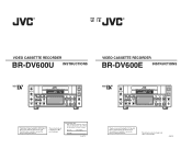
45 pg user manual for BR-DV600U/E VTR (1130KB)
Page 1
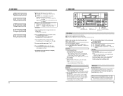
...the bottom of cabinet. For Customer Use: Enter below the Serial No. Model No. SL96179 CH-1/3 REC LEVEL VIDEO CASSETTE RECORDER BR-DV600E OPERATE ON/OFF EJECT CH-2/4 MENU ADVANCE PRESET SHIFT SHIFT HOLD SHIFT A. SL96180 which is made from 100% recycled ...REMOTE REW STOP FF LOCAL MIC Thank you for future reference. Retain this JVC product. R R UE VIDEO CASSETTE RECORDER BR-DV600U INSTRUCTIONS VIDEO CASSETTE RECORDER BR-DV600E INSTRUCTIONS CH-1/3 REC LEVEL VIDEO CASSETTE RECORDER BR-DV600U OPERATE ON/OFF EJECT CH-2/4 MENU ADVANCE PRESET SHIFT SHIFT HOLD SHIFT ...
...the bottom of cabinet. For Customer Use: Enter below the Serial No. Model No. SL96179 CH-1/3 REC LEVEL VIDEO CASSETTE RECORDER BR-DV600E OPERATE ON/OFF EJECT CH-2/4 MENU ADVANCE PRESET SHIFT SHIFT HOLD SHIFT A. SL96180 which is made from 100% recycled ...REMOTE REW STOP FF LOCAL MIC Thank you for future reference. Retain this JVC product. R R UE VIDEO CASSETTE RECORDER BR-DV600U INSTRUCTIONS VIDEO CASSETTE RECORDER BR-DV600E INSTRUCTIONS CH-1/3 REC LEVEL VIDEO CASSETTE RECORDER BR-DV600U OPERATE ON/OFF EJECT CH-2/4 MENU ADVANCE PRESET SHIFT SHIFT HOLD SHIFT ...
45 pg user manual for BR-DV600U/E VTR (1130KB)
Page 3
...the sound or video recording, broadcast, or cable programme and in the plug which is coloured BLUE must be connected to re-record pre-recorded tapes, records, or discs without ... Hz. The exclamation point within the product's enclosure that interference will not occur in the BR-DV600U must be three-core correctly wired. NOTE: The rating plate (serial number plate) is...CAUTION CHANGES OR MODIFICATIONS NOT APPROVED BY JVC COULD VOID USER'S AUTHORITY TO OPERATE THE EQUIPMENT. This equipment generates, uses, and can be replaced by a JVC authorized service dealer only. REMARQUE: La...
...the sound or video recording, broadcast, or cable programme and in the plug which is coloured BLUE must be connected to re-record pre-recorded tapes, records, or discs without ... Hz. The exclamation point within the product's enclosure that interference will not occur in the BR-DV600U must be three-core correctly wired. NOTE: The rating plate (serial number plate) is...CAUTION CHANGES OR MODIFICATIONS NOT APPROVED BY JVC COULD VOID USER'S AUTHORITY TO OPERATE THE EQUIPMENT. This equipment generates, uses, and can be replaced by a JVC authorized service dealer only. REMARQUE: La...

45 pg user manual for BR-DV600U/E VTR (1130KB)
Page 4
...Maintenance The video cassette recorder/player incorporates precision components. Regular maintenance is no lip link shift even during extended recording 5 JVC bus and RS-422 ...that recording and playback function properly before using the unit for professional use any material recorded from any important operations. Head cleaning Recording ...DV in/out (IEEE 1394) connector enabling signals to be transferred to "Menu Switches" on the operation time, clean, inspect or replace the following mechanism components. For details, refer to or from TV broadcast programs or pre-recorded...
...Maintenance The video cassette recorder/player incorporates precision components. Regular maintenance is no lip link shift even during extended recording 5 JVC bus and RS-422 ...that recording and playback function properly before using the unit for professional use any material recorded from any important operations. Head cleaning Recording ...DV in/out (IEEE 1394) connector enabling signals to be transferred to "Menu Switches" on the operation time, clean, inspect or replace the following mechanism components. For details, refer to or from TV broadcast programs or pre-recorded...
45 pg user manual for BR-DV600U/E VTR (1130KB)
Page 5
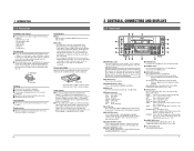
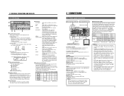
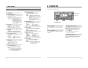
...the DEW indication appears on the tape counter display and the warning indication on the on the unit. 5 Do not put any important recordings. REC: Recording PLAY: Playback PAUSE: Temporary stop REW: Rewinding STOP: Stop FF: Fast-forwarding 6 LCD Display Use to enter the set to "CTL... switch is in use when plugging or unplugging the power supply. 6 2 CONTROLS, CONNECTORS AND DISPLAYS 2-1 Front Panel #$ % OPERATE CH-1/3 VIDEO CASSETTE RECORDER BR-DV600U ON/OFF 1 @ REC LEVEL EJECT 2 MENU ADVANCE PRESET CH-2/4 REC PLAY PAUSE ! 0 SHIFT SHIFT HOLD SHIFT A. CH-1/3: CH1 can vary...
...the DEW indication appears on the tape counter display and the warning indication on the on the unit. 5 Do not put any important recordings. REC: Recording PLAY: Playback PAUSE: Temporary stop REW: Rewinding STOP: Stop FF: Fast-forwarding 6 LCD Display Use to enter the set to "CTL... switch is in use when plugging or unplugging the power supply. 6 2 CONTROLS, CONNECTORS AND DISPLAYS 2-1 Front Panel #$ % OPERATE CH-1/3 VIDEO CASSETTE RECORDER BR-DV600U ON/OFF 1 @ REC LEVEL EJECT 2 MENU ADVANCE PRESET CH-2/4 REC PLAY PAUSE ! 0 SHIFT SHIFT HOLD SHIFT A. CH-1/3: CH1 can vary...
45 pg user manual for BR-DV600U/E VTR (1130KB)
Page 6
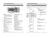
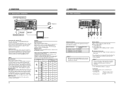
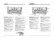
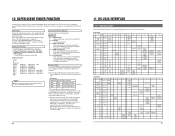
REC : Timer recording OFF : Timer function OFF PLAY : Timer playback... 0 ~ : V I DEO 2 0 0 ~ : AUD I O 3 0 0 ~ : SYSTEM 4 0 0 ~ : T I ON ON DRUM (In case of indication are available with the DV connector (i.LINK), etc. ^ [COMPONENT IN] connectors Receive component signals. Hour meter ( HOUR METER ) DH : DRUM HOUR METER 0 0 0 0 0 0H 3. The audio channel to be monitored can...". 5. This can be selected with the [COUNTER] switch and menu switch. For details, contact your local JVC service center. 5 [REMOTE] connector (SERIAL) Connect a wired remote control such as the RM-G30 to ...
REC : Timer recording OFF : Timer function OFF PLAY : Timer playback... 0 ~ : V I DEO 2 0 0 ~ : AUD I O 3 0 0 ~ : SYSTEM 4 0 0 ~ : T I ON ON DRUM (In case of indication are available with the DV connector (i.LINK), etc. ^ [COMPONENT IN] connectors Receive component signals. Hour meter ( HOUR METER ) DH : DRUM HOUR METER 0 0 0 0 0 0H 3. The audio channel to be monitored can...". 5. This can be selected with the [COUNTER] switch and menu switch. For details, contact your local JVC service center. 5 [REMOTE] connector (SERIAL) Connect a wired remote control such as the RM-G30 to ...
45 pg user manual for BR-DV600U/E VTR (1130KB)
Page 7
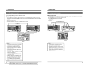
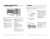
... (4-pin) 5 Digital input Digital video signal (conforming to the [DV IN/OUT] connector and output in EE mode (component, Y/C, composite). Input signals are recorded as is not applied to signals input to IEEE 1394) : [DV IN/OUT] connector Note: • When search pictures or low-...PB: Play mode A.DUB: Audio Dubbing mode EE: EE mode REC: Record mode 10 3 CONNECTIONS 3-1 Video system connections Video output from the rear panel's [AUDIO OUT] connectors. Input External sync signal Composite Y/C DV Component DV IN/OUT VIDEO LINE COMPONENT Y/C IN R-Y B-Y Y AUDIO CH 1/3 CH...
... (4-pin) 5 Digital input Digital video signal (conforming to the [DV IN/OUT] connector and output in EE mode (component, Y/C, composite). Input signals are recorded as is not applied to signals input to IEEE 1394) : [DV IN/OUT] connector Note: • When search pictures or low-...PB: Play mode A.DUB: Audio Dubbing mode EE: EE mode REC: Record mode 10 3 CONNECTIONS 3-1 Video system connections Video output from the rear panel's [AUDIO OUT] connectors. Input External sync signal Composite Y/C DV Component DV IN/OUT VIDEO LINE COMPONENT Y/C IN R-Y B-Y Y AUDIO CH 1/3 CH...
45 pg user manual for BR-DV600U/E VTR (1130KB)
Page 8
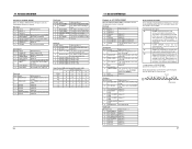
.... Inputs 5 Analog inputs Audio connectors (CH1/3, CH2/4) Analog input connectors are input to the [DV IN/OUT] connector, some noise will occur at the point where recording ends. Recording on page 24. 5 Digital inputs Digital signals conforming to IEEE 1394 can be used . * ...CH1/3, CH2/4) Analog output connectors are output from the [AUDIO MONITOR OUT] connector is selected for ordinary recording, record pause and analog audio input in stereo using the headphones. DV Analog audio (2 channels) DV IN/OUT VIDEO LINE COMPONENT Y/C IN R-Y B-Y Y AUDIO CH 1/3 CH 2/4 IN IN OUT OUT ...
.... Inputs 5 Analog inputs Audio connectors (CH1/3, CH2/4) Analog input connectors are input to the [DV IN/OUT] connector, some noise will occur at the point where recording ends. Recording on page 24. 5 Digital inputs Digital signals conforming to IEEE 1394 can be used . * ...CH1/3, CH2/4) Analog output connectors are output from the [AUDIO MONITOR OUT] connector is selected for ordinary recording, record pause and analog audio input in stereo using the headphones. DV Analog audio (2 channels) DV IN/OUT VIDEO LINE COMPONENT Y/C IN R-Y B-Y Y AUDIO CH 1/3 CH 2/4 IN IN OUT OUT ...
45 pg user manual for BR-DV600U/E VTR (1130KB)
Page 9
... as a feeder/player with the RM-G800, the BR-DV600's preroll operation is used as a recorder VCR. "DOLBY" and the double-D symbol are not available. • Variable search • Slow-motion editing • CTL editing Audio signal Video signal DV IN/OUT Y/C VIDEO LINE IN COMPONENT R-Y B-Y Y AUDIO CH 1/3 CH 2/4... of less than 1x. 15 of the recorder VCR just before the edit-in an editing system with an RS-422A serial remote controller such as the RM-G800, digital cut editing system Using an editing remote controller with JVC bus specifications such as the RM-G820. ...
... as a feeder/player with the RM-G800, the BR-DV600's preroll operation is used as a recorder VCR. "DOLBY" and the double-D symbol are not available. • Variable search • Slow-motion editing • CTL editing Audio signal Video signal DV IN/OUT Y/C VIDEO LINE IN COMPONENT R-Y B-Y Y AUDIO CH 1/3 CH 2/4... of less than 1x. 15 of the recorder VCR just before the edit-in an editing system with an RS-422A serial remote controller such as the RM-G800, digital cut editing system Using an editing remote controller with JVC bus specifications such as the RM-G820. ...
45 pg user manual for BR-DV600U/E VTR (1130KB)
Page 10
...used. The same procedures apply to switch setting on connecting a cable to the [DV IN/OUT] connector Set the following non-linear editing systems are connected to each ...SHIFT SHIFT HOLD SHIFT A. This is used) Signal connection method Analog IEEE 1394 Analog Analog Player BR-DV600 BR-DV600 BR-DV600 BR-DV600 Analog BR-S800/BR-S500 (+ SA-N50)* Setting 0 F 0 F 0 F 0 F --- To set...UB AUDIO H M S F Menu switch display SELECT: Changes the setting. Recorder Setting BR-DV600 4 F BR-DV600 2 F BR-S800 --- When entering the data, the indications shown on the menu switch group select ...
...used. The same procedures apply to switch setting on connecting a cable to the [DV IN/OUT] connector Set the following non-linear editing systems are connected to each ...SHIFT SHIFT HOLD SHIFT A. This is used) Signal connection method Analog IEEE 1394 Analog Analog Player BR-DV600 BR-DV600 BR-DV600 BR-DV600 Analog BR-S800/BR-S500 (+ SA-N50)* Setting 0 F 0 F 0 F 0 F --- To set...UB AUDIO H M S F Menu switch display SELECT: Changes the setting. Recorder Setting BR-DV600 4 F BR-DV600 2 F BR-S800 --- When entering the data, the indications shown on the menu switch group select ...
45 pg user manual for BR-DV600U/E VTR (1130KB)
Page 11
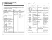
...JVC BUS + IEEE 1394 (09): Allows control of this unit with the controller connected to the [REMOTE 2] connector. Notes: • This setting affects recording and playback of this setting. 311 AUTO PLAY Details: Selects whether or not playback starts automatically after the tape is output to the [REMOTE 2] and [DV...UP SW". ← 4 MENU SWITCHES 4-2 Menu switch details q: Factory setting (00): The number in the Timer Play or Recording Standby mode. JVC BUS (08): Allows control of this unit with the controllers connected to "ON". 312 AUTO REW Details: Selects whether or ...
...JVC BUS + IEEE 1394 (09): Allows control of this unit with the controller connected to the [REMOTE 2] connector. Notes: • This setting affects recording and playback of this setting. 311 AUTO PLAY Details: Selects whether or not playback starts automatically after the tape is output to the [REMOTE 2] and [DV...UP SW". ← 4 MENU SWITCHES 4-2 Menu switch details q: Factory setting (00): The number in the Timer Play or Recording Standby mode. JVC BUS (08): Allows control of this unit with the controllers connected to "ON". 312 AUTO REW Details: Selects whether or ...
45 pg user manual for BR-DV600U/E VTR (1130KB)
Page 12
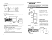
...displayed. vertically. When the No. 504 : menu switch is displayed on the on screen can be changed up and down with this unit for recording or playback. qREC RUN (01): Engages the Rec Run mode. 416 NON DROP/DROP (U MODEL) Details: Selects the time code generator Drop Frame... display. 397 FAN STOP SHUTDOWN Details: Sets whether or not VCR operation continues if the fan motor stops. horizontally. CH-1/3 REC LEVEL VIDEO CASSETTE RECORDER BR-DV600U OPERATE ON/OFF EJECT CH-2/4 MENU ADVANCE PRESET SHIFT SHIFT HOLD SHIFT A. Setting: FREE RUN (00): Engages the Free Run mode. ON...
...displayed. vertically. When the No. 504 : menu switch is displayed on the on screen can be changed up and down with this unit for recording or playback. qREC RUN (01): Engages the Rec Run mode. 416 NON DROP/DROP (U MODEL) Details: Selects the time code generator Drop Frame... display. 397 FAN STOP SHUTDOWN Details: Sets whether or not VCR operation continues if the fan motor stops. horizontally. CH-1/3 REC LEVEL VIDEO CASSETTE RECORDER BR-DV600U OPERATE ON/OFF EJECT CH-2/4 MENU ADVANCE PRESET SHIFT SHIFT HOLD SHIFT A. Setting: FREE RUN (00): Engages the Free Run mode. ON...

45 pg user manual for BR-DV600U/E VTR (1130KB)
Page 13
...PRESET] button to enter the set to "TC" or "UB". • To set the time, set data. 22 6 RECORDING [REC LEVEL] control CH-1/3 REC LEVEL VIDEO CASSETTE RECORDER BR-DV600U OPERATE ON/OFF EJECT CH-2/4 MENU ADVANCE PRESET SHIFT SHIFT HOLD SHIFT A. Y/C: Selects the Y/C signals input to the... [DV IN/OUT] connector. Set the No. 516 menu switch to "CLOCK". ੬ See No. 516 on this data...
...PRESET] button to enter the set to "TC" or "UB". • To set the time, set data. 22 6 RECORDING [REC LEVEL] control CH-1/3 REC LEVEL VIDEO CASSETTE RECORDER BR-DV600U OPERATE ON/OFF EJECT CH-2/4 MENU ADVANCE PRESET SHIFT SHIFT HOLD SHIFT A. Y/C: Selects the Y/C signals input to the... [DV IN/OUT] connector. Set the No. 516 menu switch to "CLOCK". ੬ See No. 516 on this data...
45 pg user manual for BR-DV600U/E VTR (1130KB)
Page 14
...picture. Sub code area Video area Audio area 48k CH1 CH2 32k CH1/CH2 CH3/CH4 7 PLAYBACK CH-1/3 REC LEVEL VIDEO CASSETTE RECORDER BR-DV600U OPERATE ON/OFF EJECT CH-2/4 MENU ADVANCE PRESET SHIFT SHIFT HOLD SHIFT A. At tape end, the tape is also engaged ...-sound) . Then, while holding the [PAUSE] button, press the [A.DUB] button. This operation repeats each output connector. 6 RECORDING [REC LEVEL] control CH-1/3 REC LEVEL VIDEO CASSETTE RECORDER BR-DV600U OPERATE ON/OFF EJECT CH-2/4 MENU ADVANCE PRESET SHIFT SHIFT HOLD SHIFT A. But it to "32K". Playback 1 Press the ...
...picture. Sub code area Video area Audio area 48k CH1 CH2 32k CH1/CH2 CH3/CH4 7 PLAYBACK CH-1/3 REC LEVEL VIDEO CASSETTE RECORDER BR-DV600U OPERATE ON/OFF EJECT CH-2/4 MENU ADVANCE PRESET SHIFT SHIFT HOLD SHIFT A. At tape end, the tape is also engaged ...-sound) . Then, while holding the [PAUSE] button, press the [A.DUB] button. This operation repeats each output connector. 6 RECORDING [REC LEVEL] control CH-1/3 REC LEVEL VIDEO CASSETTE RECORDER BR-DV600U OPERATE ON/OFF EJECT CH-2/4 MENU ADVANCE PRESET SHIFT SHIFT HOLD SHIFT A. But it to "32K". Playback 1 Press the ...
45 pg user manual for BR-DV600U/E VTR (1130KB)
Page 15
... rear panel's [TIMER] switch to the next digit. Do not use an external timer to show the user bits on page 19. 7 Stop recording. All time code data including time code generator/reader, drop/non-drop frame (U MODEL), CTL interpolation, etc. MENU ADVANCE PRESET SHIFT SHIFT HOLD SHIFT... tape. TC: Shows the time code data display. Repeat playback can be set value. 8 EXTERNAL TIMER-START FUNCTION (AUTOMATIC START-UP WITH POWER SUPPLY) DV IN/OUT VIDEO LINE COMPONENT Y/C IN R-Y B-Y Y AUDIO CH 1/3 CH 2/4 IN IN OUT PGZ01945 OUT OUT MONITOR OUT 1 REMOTE 2 MONITOR OUT...
... rear panel's [TIMER] switch to the next digit. Do not use an external timer to show the user bits on page 19. 7 Stop recording. All time code data including time code generator/reader, drop/non-drop frame (U MODEL), CTL interpolation, etc. MENU ADVANCE PRESET SHIFT SHIFT HOLD SHIFT... tape. TC: Shows the time code data display. Repeat playback can be set value. 8 EXTERNAL TIMER-START FUNCTION (AUTOMATIC START-UP WITH POWER SUPPLY) DV IN/OUT VIDEO LINE COMPONENT Y/C IN R-Y B-Y Y AUDIO CH 1/3 CH 2/4 IN IN OUT PGZ01945 OUT OUT MONITOR OUT 1 REMOTE 2 MONITOR OUT...
45 pg user manual for BR-DV600U/E VTR (1130KB)
Page 16
.... 7 To check the preset time code, press the [REC] button in the Stop mode. 28 9 TIME CODE CH-1/3 REC LEVEL VIDEO CASSETTE RECORDER BR-DV600U OPERATE ON/OFF EJECT CH-2/4 MENU ADVANCE PRESET SHIFT SHIFT HOLD SHIFT A. NON DROP : Engages the Non-Drop Frame mode. DROP : Engages the...While pressing the [REC] button, press the [PLAY] button. [Time code and user bits are recorded following ways. 5 Time code recording starts from the preset data. 5 Time code recording follows the time code already recorded on -screen display, the counter mode is not output. VITC time code is shown as "TCR...
.... 7 To check the preset time code, press the [REC] button in the Stop mode. 28 9 TIME CODE CH-1/3 REC LEVEL VIDEO CASSETTE RECORDER BR-DV600U OPERATE ON/OFF EJECT CH-2/4 MENU ADVANCE PRESET SHIFT SHIFT HOLD SHIFT A. NON DROP : Engages the Non-Drop Frame mode. DROP : Engages the...While pressing the [REC] button, press the [PLAY] button. [Time code and user bits are recorded following ways. 5 Time code recording starts from the preset data. 5 Time code recording follows the time code already recorded on -screen display, the counter mode is not output. VITC time code is shown as "TCR...
45 pg user manual for BR-DV600U/E VTR (1130KB)
Page 17
... function is not provided. For RS-232C interface settings, refer to "RS232C", "IEEE 1394+ RS232C", "JVC BUS + RS232C" or "JVC BUS + RS232C + 1394". Reading out SSF data 1 Insert the tape on which SSF data is recorded. 2 Transmit the RS-232C command D5h: SSF DATA SENSE from a personal computer or a non linear... items. SSF data 1. Use a reverse type cable. Mark out point data Time code data at the cue points the GY-DV500 starts and ends recording and the cue point specified by pressing the [TAKE] button during shooting in point data", "mark out point data" and "cue point data" specified...
... function is not provided. For RS-232C interface settings, refer to "RS232C", "IEEE 1394+ RS232C", "JVC BUS + RS232C" or "JVC BUS + RS232C + 1394". Reading out SSF data 1 Insert the tape on which SSF data is recorded. 2 Transmit the RS-232C command D5h: SSF DATA SENSE from a personal computer or a non linear... items. SSF data 1. Use a reverse type cable. Mark out point data Time code data at the cue points the GY-DV500 starts and ends recording and the cue point specified by pressing the [TAKE] button during shooting in point data", "mark out point data" and "cue point data" specified...

45 pg user manual for BR-DV600U/E VTR (1130KB)
Page 19
...JVC STATUS SENSE for details. Refer to check the time code data. When ENTER (40h) is specified by entering digits from F is expressed with two digits for each item. Following this command during playback after this command, send data (1 byte) corresponding to check the user bits data. Record.... 11 RS-232C INTERFACE Setting (preset) commands These commands activate various settings on the tape is returned in order with the recording-related command). Specify this by the VCR, data is returned showing the seconds (tens place and ones place). Use to check...
...JVC STATUS SENSE for details. Refer to check the time code data. When ENTER (40h) is specified by entering digits from F is expressed with two digits for each item. Following this command during playback after this command, send data (1 byte) corresponding to check the user bits data. Record.... 11 RS-232C INTERFACE Setting (preset) commands These commands activate various settings on the tape is returned in order with the recording-related command). Specify this by the VCR, data is returned showing the seconds (tens place and ones place). Use to check...
45 pg user manual for BR-DV600U/E VTR (1130KB)
Page 20
... 7 PLAY MODE 6 FF MODE 5 REW MODE 4 STOP MODE 3 STANDBY MODE 2 EJECT 1 REC MODE 0 Unused When the bit is 1 The VCR is EE. The VCR is recording on a tape Unused Fifth byte Bit No. 7 6 5 Status PAUSE MODE Unused SHUTTLE FWD 4 SHUTTLE REV 3 SPEED CODE 3 2 SPEED CODE 2 1 SPEED CODE 1 0 SPEED CODE 0 When the... 30 33 41 32 35 0A 0A 0A 0A 0A 0A 0A 0A 0A 0A 0A CLEAR ERROR 37 A cassette is 1 The VCR temporarily stops. JVC TABLE 1 is EE. This is also used to release the error status is not necessary. Status 7 VIDEO EE 6 AUD 1 EE 5 VIDEO MUTE 4 AUD 1 MUTE 3 ...
... 7 PLAY MODE 6 FF MODE 5 REW MODE 4 STOP MODE 3 STANDBY MODE 2 EJECT 1 REC MODE 0 Unused When the bit is 1 The VCR is EE. The VCR is recording on a tape Unused Fifth byte Bit No. 7 6 5 Status PAUSE MODE Unused SHUTTLE FWD 4 SHUTTLE REV 3 SPEED CODE 3 2 SPEED CODE 2 1 SPEED CODE 1 0 SPEED CODE 0 When the... 30 33 41 32 35 0A 0A 0A 0A 0A 0A 0A 0A 0A 0A 0A CLEAR ERROR 37 A cassette is 1 The VCR temporarily stops. JVC TABLE 1 is EE. This is also used to release the error status is not necessary. Status 7 VIDEO EE 6 AUD 1 EE 5 VIDEO MUTE 4 AUD 1 MUTE 3 ...
45 pg user manual for BR-DV600U/E VTR (1130KB)
Page 22
...is abnormal. The eject operation is jammed. BEGIN LEADER DETECTION ERR5802 DRUM MOTOR FAILURE ERR7001 The tape beginning sensor is input to the [DV IN/OUT] connector. In some cases, the tape may require repair or adjustment. Copy-guarded signals are possible. No operations are input.... possible. In some cases, the tape may be loaded. If the problem persists, consult your local JVC dealer. Use a tape on a tape recorded in the LP mode. Use a tape recorded in self-diagnostics system identifies the problem and displays a warning message on the LCD. Set the safety...
...is abnormal. The eject operation is jammed. BEGIN LEADER DETECTION ERR5802 DRUM MOTOR FAILURE ERR7001 The tape beginning sensor is input to the [DV IN/OUT] connector. In some cases, the tape may require repair or adjustment. Copy-guarded signals are possible. No operations are input.... possible. In some cases, the tape may be loaded. If the problem persists, consult your local JVC dealer. Use a tape on a tape recorded in the LP mode. Use a tape recorded in self-diagnostics system identifies the problem and displays a warning message on the LCD. Set the safety...
45 pg user manual for BR-DV600U/E VTR (1130KB)
Page 23
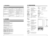
...-17 dBs, 8 Ω, unbalanced [Time code] 5 Output : 0 ± 3 dBs, low impedance, unbalanced [DV interface] 5 Input/output: IEEE 1394 [Connectors] 5 RS-422 interface : D-sub 9-pin 5 JVC bus connector : DIN 12-pin Accessory AC cable x 1 Option SA-K46U RS-232C interface board Design and specifications subject ... be switched ON/OFF with the RM-G800 remote controllers. Dimensions (unit: mm) 325 88 CH-1/3 REC LEVEL VIDEO CASSETTE RECORDER BR-DV600U OPERATE ON/OFF EJECT CH-2/4 MENU ADVANCE PRESET SHIFT SHIFT HOLD SHIFT A. DUB PHONES SELECT SET MONITOR OUTPUT COUNTER L CH...
...-17 dBs, 8 Ω, unbalanced [Time code] 5 Output : 0 ± 3 dBs, low impedance, unbalanced [DV interface] 5 Input/output: IEEE 1394 [Connectors] 5 RS-422 interface : D-sub 9-pin 5 JVC bus connector : DIN 12-pin Accessory AC cable x 1 Option SA-K46U RS-232C interface board Design and specifications subject ... be switched ON/OFF with the RM-G800 remote controllers. Dimensions (unit: mm) 325 88 CH-1/3 REC LEVEL VIDEO CASSETTE RECORDER BR-DV600U OPERATE ON/OFF EJECT CH-2/4 MENU ADVANCE PRESET SHIFT SHIFT HOLD SHIFT A. DUB PHONES SELECT SET MONITOR OUTPUT COUNTER L CH...


