

45 pg user manual for BR-DV600U/E VTR (1130KB)
Page 2
...'s instructions, and should never be used close to qualified service personnel under the following lengths: Port LINE IN LINE OUT VIDEO MONITOR OUT COMPONENT Y IN R-Y IN B-Y IN COMPONENT Y OUT R-Y OUT B-Y OUT Y/C IN Y/C OUT SYNC IN (TIMECODE IN) TIMECODE OUT AUDIO IN AUDIO OUT AUDIO MONITOR OUT SERIAL REMOTE REMOTE1(RS-422) REMOTE2(JVC BUS) DV IN/OUT MIC PHONES AC IN DC 12V Cable Coaxial Cable Coaxial Cable Coaxial Cable Coaxial Cable...
...'s instructions, and should never be used close to qualified service personnel under the following lengths: Port LINE IN LINE OUT VIDEO MONITOR OUT COMPONENT Y IN R-Y IN B-Y IN COMPONENT Y OUT R-Y OUT B-Y OUT Y/C IN Y/C OUT SYNC IN (TIMECODE IN) TIMECODE OUT AUDIO IN AUDIO OUT AUDIO MONITOR OUT SERIAL REMOTE REMOTE1(RS-422) REMOTE2(JVC BUS) DV IN/OUT MIC PHONES AC IN DC 12V Cable Coaxial Cable Coaxial Cable Coaxial Cable Coaxial Cable...
45 pg user manual for BR-DV600U/E VTR (1130KB)
Page 3
... in the sound or video recording, broadcast, or cable programme and in a particular installation. Cette tension est suffisante pour provoquer l'électrocution de personnes. WARNING: The battery used , must be replaced by one or more of the unit. POWER SYSTEM Connection to radio communications. The wire which is coloured BLUE must be unlawful to constitute a risk of important operating and maintenance (servicing) instructions in...
... in the sound or video recording, broadcast, or cable programme and in a particular installation. Cette tension est suffisante pour provoquer l'électrocution de personnes. WARNING: The battery used , must be replaced by one or more of the unit. POWER SYSTEM Connection to radio communications. The wire which is coloured BLUE must be unlawful to constitute a risk of important operating and maintenance (servicing) instructions in...

45 pg user manual for BR-DV600U/E VTR (1130KB)
Page 4
... Front Panel 7 2-2 Rear Panel 8 2-3 On-Screen Display 9 2-4 LCD Display 10 3 CONNECTIONS 3-1 Video system connections 11 3-2 Audio system connections 12 3-3 Other connections 13 3-4 Editing system examples 14 4 MENU SWITCHES 4-1 Menu switch organization 17 4-2 Menu switch details 18 5 PREPARATION Turn the power ON/OFF 21 Loading/unloading a cassette 21 Audio monitor selection 21 Built-in clock setting 22 6 RECORDING Recording preparation 23 Recording 23 Audio dubbing 24 Reference 24 7 PLAYBACK Playback preparation 25 Playback 25 Repeat play back correctly due to digital...
... Front Panel 7 2-2 Rear Panel 8 2-3 On-Screen Display 9 2-4 LCD Display 10 3 CONNECTIONS 3-1 Video system connections 11 3-2 Audio system connections 12 3-3 Other connections 13 3-4 Editing system examples 14 4 MENU SWITCHES 4-1 Menu switch organization 17 4-2 Menu switch details 18 5 PREPARATION Turn the power ON/OFF 21 Loading/unloading a cassette 21 Audio monitor selection 21 Built-in clock setting 22 6 RECORDING Recording preparation 23 Recording 23 Audio dubbing 24 Reference 24 7 PLAYBACK Playback preparation 25 Playback 25 Repeat play back correctly due to digital...
45 pg user manual for BR-DV600U/E VTR (1130KB)
Page 5
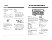
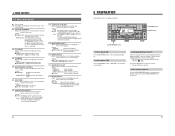
... it is recommended that you use dirty or damaged tapes. Use as a supplementary power source or for UB. 8 [AUDIO OUTPUT] switch Use to select the audio channel to output from the rear panel's [AUDIO MONITOR OUT] connectors. 0 [PHONES] jack Connect a set the menu switch setting mode. Condensation Condensation 5 Do not use when plugging or unplugging the power supply. 6 2 CONTROLS, CONNECTORS AND DISPLAYS 2-1 Front Panel #$ % OPERATE CH-1/3 VIDEO CASSETTE RECORDER BR-DV600U ON/OFF 1 @ REC LEVEL EJECT 2 MENU ADVANCE PRESET CH-2/4 REC PLAY PAUSE ! 0 SHIFT SHIFT HOLD...
... it is recommended that you use dirty or damaged tapes. Use as a supplementary power source or for UB. 8 [AUDIO OUTPUT] switch Use to select the audio channel to output from the rear panel's [AUDIO MONITOR OUT] connectors. 0 [PHONES] jack Connect a set the menu switch setting mode. Condensation Condensation 5 Do not use when plugging or unplugging the power supply. 6 2 CONTROLS, CONNECTORS AND DISPLAYS 2-1 Front Panel #$ % OPERATE CH-1/3 VIDEO CASSETTE RECORDER BR-DV600U ON/OFF 1 @ REC LEVEL EJECT 2 MENU ADVANCE PRESET CH-2/4 REC PLAY PAUSE ! 0 SHIFT SHIFT HOLD...
45 pg user manual for BR-DV600U/E VTR (1130KB)
Page 6
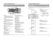
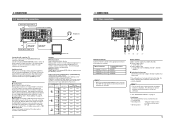
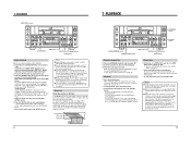
2 CONTROLS, CONNECTORS AND DISPLAYS 2-2 Rear Panel ^ & * ( ) % $ # DV IN/OUT Y/C VIDEO LINE IN COMPONENT R-Y B-Y Y AUDIO CH 1/3 CH 2/4 IN IN OUT @ ! Tape counter Time display STOP Mode TCR 1 2 : 0 0 : 0 0 : 0 0 Counter mode Counter mode indication CTL TCR TCG UBR UBG TIME DATE Time display contents CTL counter data Time code reader data Time code generator data User bits reader data User bits generator data Time Date 1. Shown when the No. 505 menu switch is set to check the output video or on the monitor screen. Warning message Automatically shown ...
2 CONTROLS, CONNECTORS AND DISPLAYS 2-2 Rear Panel ^ & * ( ) % $ # DV IN/OUT Y/C VIDEO LINE IN COMPONENT R-Y B-Y Y AUDIO CH 1/3 CH 2/4 IN IN OUT @ ! Tape counter Time display STOP Mode TCR 1 2 : 0 0 : 0 0 : 0 0 Counter mode Counter mode indication CTL TCR TCG UBR UBG TIME DATE Time display contents CTL counter data Time code reader data Time code generator data User bits reader data User bits generator data Time Date 1. Shown when the No. 505 menu switch is set to check the output video or on the monitor screen. Warning message Automatically shown ...
45 pg user manual for BR-DV600U/E VTR (1130KB)
Page 7
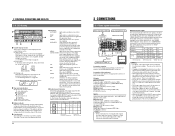
...-forward mode Play mode Pause mode Reverse search mode Fast-forward search mode 3 Battery indicator When this unit is insufficient. Indication and output signals can be locked. • Plugging and unplugging the external sync or video signal connector during operation causes distortion in the picture and sound for external sync signal. • When video signals are synchronized in the lower section of the monitor screen. AUD LOCK: Lights when the video and audio sampling clocks (at a time. Input...
...-forward mode Play mode Pause mode Reverse search mode Fast-forward search mode 3 Battery indicator When this unit is insufficient. Indication and output signals can be locked. • Plugging and unplugging the external sync or video signal connector during operation causes distortion in the picture and sound for external sync signal. • When video signals are synchronized in the lower section of the monitor screen. AUD LOCK: Lights when the video and audio sampling clocks (at a time. Input...
45 pg user manual for BR-DV600U/E VTR (1130KB)
Page 8
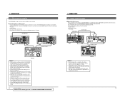
... to turn the VCR OFF. Audio input from a VCR, etc. When audio signals are output from the [AUDIO MONITOR OUT] connector is monaural. Use the front panel [AUDIO OUTPUT] switch to select the audio channels you want to a VCR, etc. Headphones jack Audio can be adjusted. In this unit continuously when the battery indicator is displayed. For audio dubbing, refer to "Audio dubbing" on page 24. 5 Digital inputs Digital signals conforming to the [DV IN/OUT] connector. For MiniDV format, use...
... to turn the VCR OFF. Audio input from a VCR, etc. When audio signals are output from the [AUDIO MONITOR OUT] connector is monaural. Use the front panel [AUDIO OUTPUT] switch to select the audio channels you want to a VCR, etc. Headphones jack Audio can be adjusted. In this unit continuously when the battery indicator is displayed. For audio dubbing, refer to "Audio dubbing" on page 24. 5 Digital inputs Digital signals conforming to the [DV IN/OUT] connector. For MiniDV format, use...
45 pg user manual for BR-DV600U/E VTR (1130KB)
Page 9
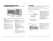
... MONITOR OUT 1 REMOTE 2 MONITOR OUT SYNC IN TIME CODE SPARE TIMER SERIAL REC PLAY DC 12V OFF Remote control COUNTER TC HOLD CTL TC UB PRESET GPI EDITING CONTROL UNIT RM-G800 IN OUT HOUR MINUTE SECOND FRAME LAP LAP MENU SET SET ON PLAYER COUNTER RESET EJECT RECORDER OFF ASSEM EDIT MODE VIDEO/Hi-Fi AUD-1 AUD-2 REC REW PLAY STILL FF SEARCH MANUAL TAKE SHIFT PREVIEW REVIEW ENTRY MENU CANCEL GOTO PLAYER...
... MONITOR OUT 1 REMOTE 2 MONITOR OUT SYNC IN TIME CODE SPARE TIMER SERIAL REC PLAY DC 12V OFF Remote control COUNTER TC HOLD CTL TC UB PRESET GPI EDITING CONTROL UNIT RM-G800 IN OUT HOUR MINUTE SECOND FRAME LAP LAP MENU SET SET ON PLAYER COUNTER RESET EJECT RECORDER OFF ASSEM EDIT MODE VIDEO/Hi-Fi AUD-1 AUD-2 REC REW PLAY STILL FF SEARCH MANUAL TAKE SHIFT PREVIEW REVIEW ENTRY MENU CANCEL GOTO PLAYER...
45 pg user manual for BR-DV600U/E VTR (1130KB)
Page 10
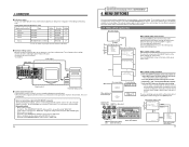
... menu switch group select screen. Menu switch setting screen To access this switch is currently set to turn the power OFF and ON again.) • When used ) Signal connection method Analog IEEE 1394 Analog Analog Player BR-DV600 BR-DV600 BR-DV600 BR-DV600 Analog BR-S800/BR-S500 (+ SA-N50)* Setting 0 F 0 F 0 F 0 F --- DUB SELECT SET CH 1/3 40 30 20 10 CH 2/4 32k 48k AUD LOCK OVER AUTO OFF DEW 0 dB OVER SERVO RF PB NDF HOLD MONITOR OUTPUT...
... menu switch group select screen. Menu switch setting screen To access this switch is currently set to turn the power OFF and ON again.) • When used ) Signal connection method Analog IEEE 1394 Analog Analog Player BR-DV600 BR-DV600 BR-DV600 BR-DV600 Analog BR-S800/BR-S500 (+ SA-N50)* Setting 0 F 0 F 0 F 0 F --- DUB SELECT SET CH 1/3 40 30 20 10 CH 2/4 32k 48k AUD LOCK OVER AUTO OFF DEW 0 dB OVER SERVO RF PB NDF HOLD MONITOR OUTPUT...
45 pg user manual for BR-DV600U/E VTR (1130KB)
Page 11
... using DC power, set value on the rear panel. Setting: qOFF (00):The tape is not activated. Setting: IEEE 1394 (01): Allows control of this case, analog audio signals are enabled. JVC BUS + RS422A (12): Allows control of analog video signals. • Picture hue and brightness can be affected if dubbing is repeated without applying a setup suitable to video signals. 18 For servicing See the service manual page 1-19 "1.11 SET UP SW". ← 4 MENU SWITCHES 4-2 Menu switch...
... using DC power, set value on the rear panel. Setting: qOFF (00):The tape is not activated. Setting: IEEE 1394 (01): Allows control of this case, analog audio signals are enabled. JVC BUS + RS422A (12): Allows control of analog video signals. • Picture hue and brightness can be affected if dubbing is repeated without applying a setup suitable to video signals. 18 For servicing See the service manual page 1-19 "1.11 SET UP SW". ← 4 MENU SWITCHES 4-2 Menu switch...
45 pg user manual for BR-DV600U/E VTR (1130KB)
Page 12
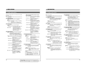
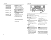
... HOLD AUD LOCK SP MENU H M S F REC PLAY PAUSE REMOTE REW STOP FF LOCAL MIC [OPERATE] button [EJECT] button [AUDIO MONITOR] switch Turn the power ON. Press the [OPERATE] switch. Loading/unloading a cassette Insert the cassette into the cassette loading slot with the window facing up . qON (01): The display is shown. 501 CHARACTER H.POSITION Details: Moves the display position of data displayed on screen, etc. Setting: qTC (00): Shows the time code data. Setting: OFF (00): The display is not...
... HOLD AUD LOCK SP MENU H M S F REC PLAY PAUSE REMOTE REW STOP FF LOCAL MIC [OPERATE] button [EJECT] button [AUDIO MONITOR] switch Turn the power ON. Press the [OPERATE] switch. Loading/unloading a cassette Insert the cassette into the cassette loading slot with the window facing up . qON (01): The display is shown. 501 CHARACTER H.POSITION Details: Moves the display position of data displayed on screen, etc. Setting: qTC (00): Shows the time code data. Setting: OFF (00): The display is not...

45 pg user manual for BR-DV600U/E VTR (1130KB)
Page 13
... HOLD SHIFT A. Set the No. 516 menu switch to prevent the tape from being used up (Operate On mode). Press the [HOLD] button. • Clock setting [ The hour digit starts to blink. • Date setting [ The month (U MODEL), day (E MODEL) digit starts to the [DV IN/OUT] connector. Repeat steps 4 to 5 to the time display. IEEE 1394: Selects the digital video signals and the digital audio signals input to blink. 4 Change the value. To stop recording. In the Play mode, this unit...
... HOLD SHIFT A. Set the No. 516 menu switch to prevent the tape from being used up (Operate On mode). Press the [HOLD] button. • Clock setting [ The hour digit starts to blink. • Date setting [ The month (U MODEL), day (E MODEL) digit starts to the [DV IN/OUT] connector. Repeat steps 4 to 5 to the time display. IEEE 1394: Selects the digital video signals and the digital audio signals input to blink. 4 Change the value. To stop recording. In the Play mode, this unit...
45 pg user manual for BR-DV600U/E VTR (1130KB)
Page 14
... use a tape recorded with digital audio input.) 2 Press the [PLAY] button to play 1 Set the No. 311 and No. 312 menu switches to start recording audio. and No. 312 on CH3 and CH4. Audio dubbing itself is proceeded normally. 5 It is shown and the VCR enters the Stop mode. 4 Adjust the audio recording level with the remote controller or reverse slow playback continues for example, if a section of tape recorded using 48 kHz sampling is not a trouble of BR...
... use a tape recorded with digital audio input.) 2 Press the [PLAY] button to play 1 Set the No. 311 and No. 312 menu switches to start recording audio. and No. 312 on CH3 and CH4. Audio dubbing itself is proceeded normally. 5 It is shown and the VCR enters the Stop mode. 4 Adjust the audio recording level with the remote controller or reverse slow playback continues for example, if a section of tape recorded using 48 kHz sampling is not a trouble of BR...
45 pg user manual for BR-DV600U/E VTR (1130KB)
Page 15
... time code is supplied, playback starts automati- On-screen display S TOP TCR 1 2 : 0 0 : 0 0 : 0 0 (U MODEL) : - Time code presetting is supplied, the VCR automatically enters the Record mode. Playback 1 Connect the power cable. To turn this unit or the tape. 9 TIME CODE The time code is used to "REC". 6 When power is described below. Press the [STOP] button. ADVANCE: Changes the value. Set the front panel's [REMOTE/LOCAL] switch to "LOCAL". 2 Select the video input. 3 Adjust the audio recording level. 4 Insert a cassette. 5 Set the rear panel's [TIMER] switch...
... time code is supplied, playback starts automati- On-screen display S TOP TCR 1 2 : 0 0 : 0 0 : 0 0 (U MODEL) : - Time code presetting is supplied, the VCR automatically enters the Record mode. Playback 1 Connect the power cable. To turn this unit or the tape. 9 TIME CODE The time code is used to "REC". 6 When power is described below. Press the [STOP] button. ADVANCE: Changes the value. Set the front panel's [REMOTE/LOCAL] switch to "LOCAL". 2 Select the video input. 3 Adjust the audio recording level. 4 Insert a cassette. 5 Set the rear panel's [TIMER] switch...
45 pg user manual for BR-DV600U/E VTR (1130KB)
Page 16
... Stop mode. 28 9 TIME CODE CH-1/3 REC LEVEL VIDEO CASSETTE RECORDER BR-DV600U OPERATE ON/OFF EJECT CH-2/4 MENU ADVANCE PRESET SHIFT SHIFT HOLD SHIFT A. On the on -screen display and counter display. Note on time code playback without user bits 5 When you play back the time code and user bits. Release your finger from the rear panel's [TIME CODE OUT] connector. While pressing the [REC] button, press the [PLAY] button. [The time code and user bits are recorded. The time code data is complete. 5 Set...
... Stop mode. 28 9 TIME CODE CH-1/3 REC LEVEL VIDEO CASSETTE RECORDER BR-DV600U OPERATE ON/OFF EJECT CH-2/4 MENU ADVANCE PRESET SHIFT SHIFT HOLD SHIFT A. On the on -screen display and counter display. Note on time code playback without user bits 5 When you play back the time code and user bits. Release your finger from the rear panel's [TIME CODE OUT] connector. While pressing the [REC] button, press the [PLAY] button. [The time code and user bits are recorded. The time code data is complete. 5 Set...
45 pg user manual for BR-DV600U/E VTR (1130KB)
Page 17
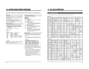
... tables This section provides information on page 32. Set the No. 050 menu switch to "RS-232C specifications" on programming VCR operations via the RS-232C interface. Cue point data Time code data at no charge on which SSF data is recorded. 2 Transmit the RS-232C command D5h: SSF DATA SENSE from the VCR. (Display example) START ID REEL NO. Recordings Model ID 0001 0002 0003 : Reel No. 0222...
... tables This section provides information on page 32. Set the No. 050 menu switch to "RS-232C specifications" on programming VCR operations via the RS-232C interface. Cue point data Time code data at no charge on which SSF data is recorded. 2 Transmit the RS-232C command D5h: SSF DATA SENSE from the VCR. (Display example) START ID REEL NO. Recordings Model ID 0001 0002 0003 : Reel No. 0222...

45 pg user manual for BR-DV600U/E VTR (1130KB)
Page 19
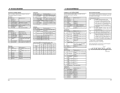
... check the time code data. High Low 1 3 (fixed) 2 5 Counter mode TC CTL UB 8E DATE PRESET 8F TIME PRESET Use to set the preroll time. Transmit this command. The number of month, day and year. Use to set , transmit the time data following this command during playback after transmitting REC DUB REQUEST. The uppermost digit shows plus or minus. Refer to select the counter mode. Use to JVC STATUS...
... check the time code data. High Low 1 3 (fixed) 2 5 Counter mode TC CTL UB 8E DATE PRESET 8F TIME PRESET Use to set the preroll time. Transmit this command. The number of month, day and year. Use to set , transmit the time data following this command during playback after transmitting REC DUB REQUEST. The uppermost digit shows plus or minus. Refer to select the counter mode. Use to JVC STATUS...
45 pg user manual for BR-DV600U/E VTR (1130KB)
Page 20
... is 1 Video output is in the TCG mode. 6 USERS BIT The counter mode is set to the UB mode. 5 TIME CODE The counter mode is set to the TC mode. 4 CTL PULSE The counter mode is set to the CTL mode. 3 CTL interpolation Always 0 2 DROP FRAME The current time code is fast-forwarding a tape. The VCR is EE. A cassette is shuttle-searching in the VCR. Always 0 The VCR is being ejected. Always 0 (E MODEL) 1 LTC...
... is 1 Video output is in the TCG mode. 6 USERS BIT The counter mode is set to the UB mode. 5 TIME CODE The counter mode is set to the TC mode. 4 CTL PULSE The counter mode is set to the CTL mode. 3 CTL interpolation Always 0 2 DROP FRAME The current time code is fast-forwarding a tape. The VCR is EE. A cassette is shuttle-searching in the VCR. Always 0 The VCR is being ejected. Always 0 (E MODEL) 1 LTC...
45 pg user manual for BR-DV600U/E VTR (1130KB)
Page 22
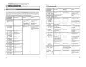
... the problem persists, consult your nearest JVC dealer. Use a tape on which NTSC (U MODEL), PAL (E MODEL) signals are possible. Operation continues. SSF INHIBIT SSFiNh FAN MOTOR FAILURE FAN STOP SSF data error occurs. Use a tape on which SSF data has been properly recorded. The operation continues. The tape ends. A tape recorded in microprocessor is input to "ENABLE"). No operations are input. Operation continues. Copy-guarded signals cannot be damaged, so use the unit until the AUTO OFF mode is set...
... the problem persists, consult your nearest JVC dealer. Use a tape on which NTSC (U MODEL), PAL (E MODEL) signals are possible. Operation continues. SSF INHIBIT SSFiNh FAN MOTOR FAILURE FAN STOP SSF data error occurs. Use a tape on which SSF data has been properly recorded. The operation continues. The tape ends. A tape recorded in microprocessor is input to "ENABLE"). No operations are input. Operation continues. Copy-guarded signals cannot be damaged, so use the unit until the AUTO OFF mode is set...
45 pg user manual for BR-DV600U/E VTR (1130KB)
Page 23
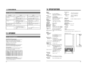
... playback picture. • The heads are used to change without notice. Types VC-G30U VC-G50U VC-G3030 VC-G2030 VC-G2050 Input 4-pin 4-pin 4-pin 7-pin 7-pin Output 4-pin 4-pin 7-pin 4-pin 4-pin Length 3 m 5 m 3 m 3 m 5 m VC-G8030U remote extended cable This extended cable is 3 m. 42 14 SPECIFICATIONS General 5 Power requirements 5 Power consumption 5 Dimensions 5 Weight 5 Temperature Operating Storage 5 Humidity Operating 5 Format 5 Signal format 5 Usable tape 5 Tape width 5 Tape speed 5 Record/play time 5 FF/rewind time...
... playback picture. • The heads are used to change without notice. Types VC-G30U VC-G50U VC-G3030 VC-G2030 VC-G2050 Input 4-pin 4-pin 4-pin 7-pin 7-pin Output 4-pin 4-pin 7-pin 4-pin 4-pin Length 3 m 5 m 3 m 3 m 5 m VC-G8030U remote extended cable This extended cable is 3 m. 42 14 SPECIFICATIONS General 5 Power requirements 5 Power consumption 5 Dimensions 5 Weight 5 Temperature Operating Storage 5 Humidity Operating 5 Format 5 Signal format 5 Usable tape 5 Tape width 5 Tape speed 5 Record/play time 5 FF/rewind time...


