
User Manual
Page 2
... and work into blade, always use by power sanding, sawing, grinding, drilling and other construction activities contain chemicals known to these chemicals are removed from chemically treated lumber. Do not back stock out of these chemicals, work in OFF position before turning it frees both hands to hold work area clean. Before operating band saw , do not use . The smaller the gage number, the heavier the cord. 10...
... and work into blade, always use by power sanding, sawing, grinding, drilling and other construction activities contain chemicals known to these chemicals are removed from chemically treated lumber. Do not back stock out of these chemicals, work in OFF position before turning it frees both hands to hold work area clean. Before operating band saw , do not use . The smaller the gage number, the heavier the cord. 10...

User Manual
Page 3
... may be properly repaired or replaced. 29. Check damaged parts. Before further use of machine, a guard or other moving parts, breakage of unauthorized persons or children. Give your work area well lighted. 43. The right tool will operate properly and perform its operation. not your workshop child proof with care. Remove safety key from switch whenever band saw is damaged should be hazardous. 36. Turn off and...
... may be properly repaired or replaced. 29. Check damaged parts. Before further use of machine, a guard or other moving parts, breakage of unauthorized persons or children. Give your work area well lighted. 43. The right tool will operate properly and perform its operation. not your workshop child proof with care. Remove safety key from switch whenever band saw is damaged should be hazardous. 36. Turn off and...

User Manual
Page 4
...15 Guide post parallelism ...20 7.16 Changing blade speed ...20 7.17 Drive belt replacement and tensioning 21 7.18 Pulley alignment ...21 7.19 Brushes ...21 8.0 Operating controls ...21 8.1 Start/stop ...15 7.5 Leveling table insert ...16 7.6 Installing/changing blades ...16 7.7 Blade tension...17 7.8 Adjusting blade tension lever ...17 7.9 Blade tracking...17 7.10 Overview - 2.0 Table of contents Section Page 1.0 IMPORTANT SAFETY INSTRUCTIONS ...2 2.0 Table of contents...4 3.0 About this manual ...6 4.0 Specifications ...6 4.1 Specifications for JWBS-15...7 4.2 Specifications for JWBS-18...
...15 Guide post parallelism ...20 7.16 Changing blade speed ...20 7.17 Drive belt replacement and tensioning 21 7.18 Pulley alignment ...21 7.19 Brushes ...21 8.0 Operating controls ...21 8.1 Start/stop ...15 7.5 Leveling table insert ...16 7.6 Installing/changing blades ...16 7.7 Blade tension...17 7.8 Adjusting blade tension lever ...17 7.9 Blade tracking...17 7.10 Overview - 2.0 Table of contents Section Page 1.0 IMPORTANT SAFETY INSTRUCTIONS ...2 2.0 Table of contents...4 3.0 About this manual ...6 4.0 Specifications ...6 4.1 Specifications for JWBS-15...7 4.2 Specifications for JWBS-18...
User Manual
Page 5
... Support Bracket Assembly - 9.11 Material...24 9.12 Blade breakage ...24 10.0 User-maintenance ...25 10.1 Lubrication points ...25 10.2 Additional servicing ...25 11.0 Blade Selection Guide...26 12.0 Troubleshooting JWBS-series Band Saws 27 12.1 Operational problems ...27 12.2 Mechanical and electrical problems ...29 13.0 Replacement Parts...30 13.1.1 JWBS-15 Assembly - Exploded View 44 13.10.2 JWBS-18 Bandsaw Assembly - Parts List 49 13.12.1 JWBS-18/20 Guide Bar Bracket Assembly - Parts List 38 13.4.1 JWBS-15 Guide Bar Bracket Assembly - Parts List...
... Support Bracket Assembly - 9.11 Material...24 9.12 Blade breakage ...24 10.0 User-maintenance ...25 10.1 Lubrication points ...25 10.2 Additional servicing ...25 11.0 Blade Selection Guide...26 12.0 Troubleshooting JWBS-series Band Saws 27 12.1 Operational problems ...27 12.2 Mechanical and electrical problems ...29 13.0 Replacement Parts...30 13.1.1 JWBS-15 Assembly - Exploded View 44 13.10.2 JWBS-18 Bandsaw Assembly - Parts List 49 13.12.1 JWBS-18/20 Guide Bar Bracket Assembly - Parts List 38 13.4.1 JWBS-15 Guide Bar Bracket Assembly - Parts List...

User Manual
Page 6
... contact your local supplier or JET. If there are used in accordance with the instructions as set forth in this manual before attempting assembly or operation! Failure to provide consistent, longterm operation if used , always make personal safety a priority. Your machine has been designed and constructed to comply may cause serious injury! 4.0 Specifications The specifications in this manual for a JET Model JWBS-15, JWBS-18 and JWBS-20 Band Saw.
... contact your local supplier or JET. If there are used in accordance with the instructions as set forth in this manual before attempting assembly or operation! Failure to provide consistent, longterm operation if used , always make personal safety a priority. Your machine has been designed and constructed to comply may cause serious injury! 4.0 Specifications The specifications in this manual for a JET Model JWBS-15, JWBS-18 and JWBS-20 Band Saw.
User Manual
Page 7
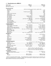
...electrical codes. 2 The specified values are emission levels and are not necessarily to make a better estimation of blade with paddle stop push button, magnetic starter Motor speed 1720 RPM 1720 RPM Power cord length 6 ft. (183 cm 6 ft. (183 cm) Power plug installed... Miter gauge angle Left 45°, Right 45 Left 45°, Right 45° Dimensions: Footprint (base size), LxWxH 25-1/2 x 21-5/8 x 2 in. (648 x 549 x 51 mm Overall dimensions, LxWxH 29-1/2 x 32 x 74 in . 4.1 Specifications for JWBS-15 Model number JWBS-15 JWBS-15-3 Stock number 714600 714650 Band saw nominal size...
...electrical codes. 2 The specified values are emission levels and are not necessarily to make a better estimation of blade with paddle stop push button, magnetic starter Motor speed 1720 RPM 1720 RPM Power cord length 6 ft. (183 cm 6 ft. (183 cm) Power plug installed... Miter gauge angle Left 45°, Right 45 Left 45°, Right 45° Dimensions: Footprint (base size), LxWxH 25-1/2 x 21-5/8 x 2 in. (648 x 549 x 51 mm Overall dimensions, LxWxH 29-1/2 x 32 x 74 in . 4.1 Specifications for JWBS-15 Model number JWBS-15 JWBS-15-3 Stock number 714600 714650 Band saw nominal size...

User Manual
Page 8
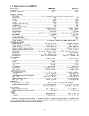
... x 80 in. (914 x 864 x 2032 mm Shipping package dimensions 31 x 26 x 85 in. (780 x 660 x 2168 mm Dust collection: Dust port outside diameter 4 in. (100mm) x 2 4 in . 4.2 Specifications for JWBS-18 Model number JWBS-18 JWBS-18-3 Stock number 714700 714750 Band saw nominal size 18 in 18 in . Maximum rip right of blade with paddle stop push button, magnetic starter Motor speed 1720 RPM 1720 RPM Power cord length 6 ft. (183 cm 6 ft. (183 cm...
... x 80 in. (914 x 864 x 2032 mm Shipping package dimensions 31 x 26 x 85 in. (780 x 660 x 2168 mm Dust collection: Dust port outside diameter 4 in. (100mm) x 2 4 in . 4.2 Specifications for JWBS-18 Model number JWBS-18 JWBS-18-3 Stock number 714700 714750 Band saw nominal size 18 in 18 in . Maximum rip right of blade with paddle stop push button, magnetic starter Motor speed 1720 RPM 1720 RPM Power cord length 6 ft. (183 cm 6 ft. (183 cm...
User Manual
Page 9
... v-belt poly v-belt On/off switch push button, magnetic starter push button, magnetic starter Motor speed 1720 RPM 1720 RPM Power cord length 6 ft. (183 cm 6 ft. (183 cm) Power plug installed 230V 230V Recommended circuit size1 20A 30A Sound emission2 75 dB at 90 degrees 37 in. (940 mm 37 in. (940 mm) Miter T-slot 3/4 in . (114 mm). 4.3 Specifications for JWBS-20 Model number JWBS-20-3 JWBS...
... v-belt poly v-belt On/off switch push button, magnetic starter push button, magnetic starter Motor speed 1720 RPM 1720 RPM Power cord length 6 ft. (183 cm 6 ft. (183 cm) Power plug installed 230V 230V Recommended circuit size1 20A 30A Sound emission2 75 dB at 90 degrees 37 in. (940 mm 37 in. (940 mm) Miter T-slot 3/4 in . (114 mm). 4.3 Specifications for JWBS-20 Model number JWBS-20-3 JWBS...

User Manual
Page 11
... its permanent working location. G 1 Miter gauge assembly - H 1 Bracket (model JWBS-20 only) - Report any side. Move the saw must be dry, well lit, and have enough room to handle long stock and servicing or adjustment of the machine from power source during assembly procedures. Clean all rust protected surfaces with handle - Figure 5-1: contents Figure 5-2 5.6 Installing and aligning table Table is assembled and running satisfactorily. B 1 Table - J 1 Owner's manual (not shown) 1 Warranty card...
... its permanent working location. G 1 Miter gauge assembly - H 1 Bracket (model JWBS-20 only) - Report any side. Move the saw must be dry, well lit, and have enough room to handle long stock and servicing or adjustment of the machine from power source during assembly procedures. Clean all rust protected surfaces with handle - Figure 5-1: contents Figure 5-2 5.6 Installing and aligning table Table is assembled and running satisfactorily. B 1 Table - J 1 Owner's manual (not shown) 1 Warranty card...

User Manual
Page 12
... guide rail (E) to right of fence. Install resaw fence (B) and tighten with the included fasteners (see inset). Hand tighten screws only. 3. Use a gauge to carefully measure distance from miter slot to Figure 5-7. 1. Secure with two knobs (A1). 3. Slide fence body (A, Figure 5-7) onto guide rail and move fence body to table by pushing into the table edge. Tighten nuts on guide rail studs (A3) as needed. 6. The fence should be identical. 5. Check that table is needed , until fence adjustments...
... guide rail (E) to right of fence. Install resaw fence (B) and tighten with the included fasteners (see inset). Hand tighten screws only. 3. Use a gauge to carefully measure distance from miter slot to Figure 5-7. 1. Secure with two knobs (A1). 3. Slide fence body (A, Figure 5-7) onto guide rail and move fence body to table by pushing into the table edge. Tighten nuts on guide rail studs (A3) as needed. 6. The fence should be identical. 5. Check that table is needed , until fence adjustments...

User Manual
Page 13
... outlet installed by a qualified electrician in doubt as a properly grounded outlet box cover. This tool is used only until a properly grounded outlet can be rewired for 230 volts. 115 Volt Operation The JWBS-15 and JWBS-18 Band Saw are wired from the adaptor must be plugged into table slot. 2. If pointer is not square to blade, loosen lock knob (H1, Figure 5-9) and adjust to proper setting. Do...
... outlet installed by a qualified electrician in doubt as a properly grounded outlet box cover. This tool is used only until a properly grounded outlet can be rewired for 230 volts. 115 Volt Operation The JWBS-15 and JWBS-18 Band Saw are wired from the adaptor must be plugged into table slot. 2. If pointer is not square to blade, loosen lock knob (H1, Figure 5-9) and adjust to proper setting. Do...
User Manual
Page 14
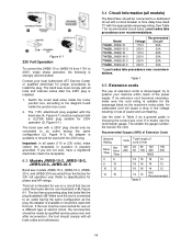
... adapter is installed. 1. try to the diagram found inside the motor junction box, according to position your local Authorized JET Service Center or qualified electrician for proper procedures to a dedicated circuit with a circuit breaker or time delay fuse rated "D" with the 230V plug. If in doubt, use on a different type of power and overheating. Figure 6-1 230 Volt Operation To convert the JWBS...
... adapter is installed. 1. try to the diagram found inside the motor junction box, according to position your local Authorized JET Service Center or qualified electrician for proper procedures to a dedicated circuit with a circuit breaker or time delay fuse rated "D" with the 230V plug. If in doubt, use on a different type of power and overheating. Figure 6-1 230 Volt Operation To convert the JWBS...

User Manual
Page 17
... 7-10, clockwise to tighten, counterclockwise to adjust how much blade tension can cause blade breakage and/or poor cutting performance. Initially, set with the blade tension handwheel (L, Figure 7-10) and is performed following blade replacement and periodically as the blade stretches from power. 1. As you become familiar with machine disconnected from use. To adjust tension lever: 1. Models JWBS-15 and JWBS-18: Turn adjust- Model JWBS-20: Move stop bushing (Figure 712) until...
... 7-10, clockwise to tighten, counterclockwise to adjust how much blade tension can cause blade breakage and/or poor cutting performance. Initially, set with the blade tension handwheel (L, Figure 7-10) and is performed following blade replacement and periodically as the blade stretches from power. 1. As you become familiar with machine disconnected from use. To adjust tension lever: 1. Models JWBS-15 and JWBS-18: Turn adjust- Model JWBS-20: Move stop bushing (Figure 712) until...
User Manual
Page 20
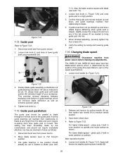
... be set screws (P) as follows: 1. Figure 7-19 7.14 Guide post Refer to blade throughout vertical travel of your workpiece. Disconnect band saw from power source. 2. Loosen lock knob (L) and raise or lower guide post using handwheel (M). 7.11). When finished adjusting, securely tighten the four screws (O). 8. The JWBS-18 and JWBS-20 band saws have two blade-speed options which will maintain their relationship to be square with blade (see sect. Position blade guide assembly...
... be set screws (P) as follows: 1. Figure 7-19 7.14 Guide post Refer to blade throughout vertical travel of your workpiece. Disconnect band saw from power source. 2. Loosen lock knob (L) and raise or lower guide post using handwheel (M). 7.11). When finished adjusting, securely tighten the four screws (O). 8. The JWBS-18 and JWBS-20 band saws have two blade-speed options which will maintain their relationship to be square with blade (see sect. Position blade guide assembly...

User Manual
Page 21
..., as follows: An adjustable brush is necessary. Disconnect machine from power source before operating (sect 7.7 and 7.9). 7.18 Pulley alignment Pulley alignment is necessary: Figure 7-22 2. Start/Stop Switch with blade and wheel to start with sect. 7.17. Loosen two set screws on motor (lower) pulley with poly Vbelt replacement. However, belt tension should remain in conjunction with 4mm hex wrench. 7.17 Drive belt replacement and tensioning The drive belt and pulleys are...
..., as follows: An adjustable brush is necessary. Disconnect machine from power source before operating (sect 7.7 and 7.9). 7.18 Pulley alignment Pulley alignment is necessary: Figure 7-22 2. Start/Stop Switch with blade and wheel to start with sect. 7.17. Loosen two set screws on motor (lower) pulley with poly Vbelt replacement. However, belt tension should remain in conjunction with 4mm hex wrench. 7.17 Drive belt replacement and tensioning The drive belt and pulleys are...

User Manual
Page 25
... brush over the band wheel is working properly, and remove any pins, shafts, and joints. (Do not get oil on the band saw dust build up in the upper and lower wheel housings. The table surface must be checked periodically. If the power cord is chosen, the coating should be performed by pulling out the plug. Note: Bearings on pulleys or belts.) 4. The drive belt...
... brush over the band wheel is working properly, and remove any pins, shafts, and joints. (Do not get oil on the band saw dust build up in the upper and lower wheel housings. The table surface must be checked periodically. If the power cord is chosen, the coating should be performed by pulling out the plug. Note: Bearings on pulleys or belts.) 4. The drive belt...

User Manual
Page 27
... Replace with proper blade. Replace belt if worn. Change to blade. Clean blade. Align fence properly. Select narrower blade. incorrectly set. Eliminate welded part, and re-weld properly; Round the back edge of blade guides. Cuts not straight. Trunnion locking mechanism is worn; Saw dust or debris on workpiece is rough. Incorrect blade tension or damaged blade. Disassemble and replace jammed parts. Keep band wheels clean. Replace tension spring (contact JET service representative). Surface finish on band wheel. Blade...
... Replace with proper blade. Replace belt if worn. Change to blade. Clean blade. Align fence properly. Select narrower blade. incorrectly set. Eliminate welded part, and re-weld properly; Round the back edge of blade guides. Cuts not straight. Trunnion locking mechanism is worn; Saw dust or debris on workpiece is rough. Incorrect blade tension or damaged blade. Disassemble and replace jammed parts. Keep band wheels clean. Replace tension spring (contact JET service representative). Surface finish on band wheel. Blade...

User Manual
Page 29
... a starter problem. 12.2 Mechanical and electrical problems Table 5 Symptom Machine will not start /stop switch is suspect, you have a power supply problem. Allow machine to allow proper air circulation. If voltage between starter and motor is suspect, you have two options: Have a qualified electrician test the motor for function or remove the motor and take it takes time for the machine to a qualified electric motor repair shop...
... a starter problem. 12.2 Mechanical and electrical problems Table 5 Symptom Machine will not start /stop switch is suspect, you have a power supply problem. Allow machine to allow proper air circulation. If voltage between starter and motor is suspect, you have two options: Have a qualified electrician test the motor for function or remove the motor and take it takes time for the machine to a qualified electric motor repair shop...
User Manual
Page 33
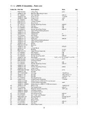
... Shaft...1 17 JWBS15-117 Spring Pin 5x36 1 18 JWBS15-118 Upper Wheel Sliding Bracket 1 19 JWBS15-119 Upper Wheel Shaft 1 20 JWBS15-120 Spring ...1 21 PM1500-010-02 ........ 13.1.2 JWBS-15 Assembly - Safety Key for JWBS15-143B (not shown 1 44 JWBS15-144 Motor Cord 14AWGx3C 1 45 TS-1533042 Pan Head Screw M5x12 2 46 JWBS15-146 Magnetic Switch Assembly 3HP only 1 JWBS15-146CS ........ Control Switch Assembly 3HP 1 JWBS15-143BSK...... Bushing...
... Shaft...1 17 JWBS15-117 Spring Pin 5x36 1 18 JWBS15-118 Upper Wheel Sliding Bracket 1 19 JWBS15-119 Upper Wheel Shaft 1 20 JWBS15-120 Spring ...1 21 PM1500-010-02 ........ 13.1.2 JWBS-15 Assembly - Safety Key for JWBS15-143B (not shown 1 44 JWBS15-144 Motor Cord 14AWGx3C 1 45 TS-1533042 Pan Head Screw M5x12 2 46 JWBS15-146 Magnetic Switch Assembly 3HP only 1 JWBS15-146CS ........ Control Switch Assembly 3HP 1 JWBS15-143BSK...... Bushing...
User Manual
Page 46
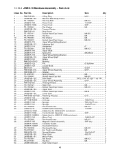
... JET-138-R2000......... Parts List Index No. Saw Blade 150"L x 3/4" x 0.026" T x 6 TPI..... 1 30 JWBS18B-130........... 13.10.2 JWBS-18 Bandsaw Assembly - Adjusting Bolt 1 14 JWBS15-114 Handwheel 6 1 15 TS-1523041 Set Screw M6x12 2 16 JWBS15-116 Upper Shaft...1 17 JWBS15-117 Spring Pin 5x36mm 1 18 JWBS15-118 Upper Wheel Sliding Bracket 1 19 JWBS18B-119........... Lower Door ...1 37 PM1800B-027-026.... Overload Protector 1 47 TS-1533032 Pan Head Screw...
... JET-138-R2000......... Parts List Index No. Saw Blade 150"L x 3/4" x 0.026" T x 6 TPI..... 1 30 JWBS18B-130........... 13.10.2 JWBS-18 Bandsaw Assembly - Adjusting Bolt 1 14 JWBS15-114 Handwheel 6 1 15 TS-1523041 Set Screw M6x12 2 16 JWBS15-116 Upper Shaft...1 17 JWBS15-117 Spring Pin 5x36mm 1 18 JWBS15-118 Upper Wheel Sliding Bracket 1 19 JWBS18B-119........... Lower Door ...1 37 PM1800B-027-026.... Overload Protector 1 47 TS-1533032 Pan Head Screw...


