Product Guide
Page 3
...to the Server Board 35 Cable Routing - Contents 1 Description Server Board Features ...9 Back Panel Connectors 10 Server Board Connector and Component Locations 11 Processor ...12 Memory ...12 Add-in Board Connectors ......13 Video ...13 SCSI Controller ...14 Modular RAID Capable PCI-X Slot 6 14 IDE Controller...14 USB Interface ...14 Network Controllers...15 Network Teaming Features 15 Keyboard and Mouse ...17 ACPI...17 Security ...17 Security with Intel® Server...
...to the Server Board 35 Cable Routing - Contents 1 Description Server Board Features ...9 Back Panel Connectors 10 Server Board Connector and Component Locations 11 Processor ...12 Memory ...12 Add-in Board Connectors ......13 Video ...13 SCSI Controller ...14 Modular RAID Capable PCI-X Slot 6 14 IDE Controller...14 USB Interface ...14 Network Controllers...15 Network Teaming Features 15 Keyboard and Mouse ...17 ACPI...17 Security ...17 Security with Intel® Server...
Product Guide
Page 6
... to the Air Intake Assembly 33 18. Attaching the Wind Tunnel Assembly 33 17. Routing Cables ...36 22. Jumper Locations...89 vi Intel Server Board SHG2 Product Guide Installing the Retention Brackets 29 11. Installing Memory ...45 27. Installing the Retention Brackets 52 28. Replacing the Back up... 11 3. Attaching the Heat Sink Fan to the I /O Shield 25 6. Aligning the Heat Sink 52 31. Back Panel Connectors 10 2. Making Connections to the Server Board 35 21. Installing the Serial B Cable 38 25. Attaching the Heat Sink and Retention Clip 52 32. Aligning the Heat...
... to the Air Intake Assembly 33 18. Attaching the Wind Tunnel Assembly 33 17. Routing Cables ...36 22. Jumper Locations...89 vi Intel Server Board SHG2 Product Guide Installing the Retention Brackets 29 11. Installing Memory ...45 27. Installing the Retention Brackets 52 28. Replacing the Back up... 11 3. Attaching the Heat Sink Fan to the I /O Shield 25 6. Aligning the Heat Sink 52 31. Back Panel Connectors 10 2. Making Connections to the Server Board 35 21. Installing the Serial B Cable 38 25. Attaching the Heat Sink and Retention Clip 52 32. Aligning the Heat...
Product Guide
Page 9
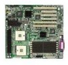
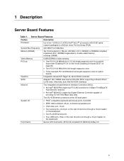
Server Board Features Feature Description Processor Up to two 1.8 GHz to 2.4 GHz Intel® Xeon™ processors with 512K cache support packaged... expansion slots • Three standard PCI 33 MHz/32-bit full-length expansion slots for add-in boards Graphics Integrated onboard ATI Rage† XL 32-bit SVGA controller SCSI Adaptec† AIC-7899W dual ... Fast Ethernet networks • An Intel® 82544GC single-chip Gigabit Ethernet Controller capable of providing 10/100/1000 Mbps data rates Two RJ-45 Ethernet connectors at the I/O back panel System I/O • PS/2†-...
Server Board Features Feature Description Processor Up to two 1.8 GHz to 2.4 GHz Intel® Xeon™ processors with 512K cache support packaged... expansion slots • Three standard PCI 33 MHz/32-bit full-length expansion slots for add-in boards Graphics Integrated onboard ATI Rage† XL 32-bit SVGA controller SCSI Adaptec† AIC-7899W dual ... Fast Ethernet networks • An Intel® 82544GC single-chip Gigabit Ethernet Controller capable of providing 10/100/1000 Mbps data rates Two RJ-45 Ethernet connectors at the I/O back panel System I/O • PS/2†-...
Product Guide
Page 10
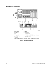
Back Panel Connectors 10 Intel Server Board SHG2 Product Guide Back Panel Connectors A B C J K E NIC2 NIC1 (Gbit) (10/100) D F G HI OM14358 A AC Power* G Video B USB 1, 2, 3 H NIC2 (Gbit) C Mouse I NIC1 (10/100) D Keyboard J ICMB/External SCSI Connector Knockout* E Parallel Port K Serial B Knockout* F Serial A * Intel SC5200 Base chassis shown here. Figure 1. Item may be different on your chassis.
Back Panel Connectors 10 Intel Server Board SHG2 Product Guide Back Panel Connectors A B C J K E NIC2 NIC1 (Gbit) (10/100) D F G HI OM14358 A AC Power* G Video B USB 1, 2, 3 H NIC2 (Gbit) C Mouse I NIC1 (10/100) D Keyboard J ICMB/External SCSI Connector Knockout* E Parallel Port K Serial B Knockout* F Serial A * Intel SC5200 Base chassis shown here. Figure 1. Item may be different on your chassis.
Product Guide
Page 11
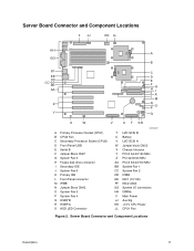
... Description 11 Server Board Connector and Component Locations II JJ KK LL HH A GG B FF EE DD CC BB AA Z Y C D E F H J G I K L M N O P Q X W V U T SR A Primary Processor Socket (CPU1) B CPU2 Fan C Secondary Processor Socket (CPU2) D Front Panel USB E Serial B F Jumper Block CN27 G System Fan 5 H Floppy disk drive connector I Secondary IDE J System Fan 6 K Primary IDE L Front Panel connector M IPMB...
... Description 11 Server Board Connector and Component Locations II JJ KK LL HH A GG B FF EE DD CC BB AA Z Y C D E F H J G I K L M N O P Q X W V U T SR A Primary Processor Socket (CPU1) B CPU2 Fan C Secondary Processor Socket (CPU2) D Front Panel USB E Serial B F Jumper Block CN27 G System Fan 5 H Floppy disk drive connector I Secondary IDE J System Fan 6 K Primary IDE L Front Panel connector M IPMB...
Product Guide
Page 14
... controller has two connectors, Primary and Secondary, located on the server board that can be cabled to a front panel board. One additional USB connector is installed, then SCSI interrupts are defined by the USB Specification, Revision 1.1. To use this feature, see : http://support.intel.com/support/motherboards/server/SHG2 IDE Controller The system includes a dual-channel enhanced IDE...
... controller has two connectors, Primary and Secondary, located on the server board that can be cabled to a front panel board. One additional USB connector is installed, then SCSI interrupts are defined by the USB Specification, Revision 1.1. To use this feature, see : http://support.intel.com/support/motherboards/server/SHG2 IDE Controller The system includes a dual-channel enhanced IDE...
Product Guide
Page 18
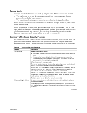
...and mouse after you enter the correct password(s). For example: • Enable the keyboard lockout timer so that the server requires a password to exit secure mode. Using Passwords You can access the system only after a specified time-out period...a user password. • Set secure mode to prevent keyboard or mouse input and to prevent use of the front panel reset and power switches. • Activate a hot-key combination to enter secure mode quickly. • Disable writing to... to prevent unauthorized or accidental access to exit secure mode. 18 Intel Server Board SHG2 Product Guide
...and mouse after you enter the correct password(s). For example: • Enable the keyboard lockout timer so that the server requires a password to exit secure mode. Using Passwords You can access the system only after a specified time-out period...a user password. • Set secure mode to prevent keyboard or mouse input and to prevent use of the front panel reset and power switches. • Activate a hot-key combination to enter secure mode quickly. • Disable writing to... to prevent unauthorized or accidental access to exit secure mode. 18 Intel Server Board SHG2 Product Guide
Product Guide
Page 19
...in effect: • You can boot the server and the operating system will be powered off . In secure mode, the server will not be powered off when secure mode is entered, the server boots from the front panel switches. However, if the front panel power switch remains depressed when secure mode is... detected in the CD-ROM drive or a diskette in secure mode: The server can secure the system simply by using the SSU...
...in effect: • You can boot the server and the operating system will be powered off . In secure mode, the server will not be powered off when secure mode is entered, the server boots from the front panel switches. However, if the front panel power switch remains depressed when secure mode is... detected in the CD-ROM drive or a diskette in secure mode: The server can secure the system simply by using the SSU...

Product Guide
Page 28
Attach the board with the screws included with your chassis at the ten locations marked below. Placing the Server Board in a bag labeled "C." 1 2 OM14363 Figure 9. For the Intel SC5200 chassis, these screws are packaged in the Chassis 28 Intel Server Board SHG2 Product Guide Installing the Server Board 1. Place the board into the chassis, making sure that the back panel I/O shield openings and chassis standoffs align correctly. 2.
Attach the board with the screws included with your chassis at the ten locations marked below. Placing the Server Board in a bag labeled "C." 1 2 OM14363 Figure 9. For the Intel SC5200 chassis, these screws are packaged in the Chassis 28 Intel Server Board SHG2 Product Guide Installing the Server Board 1. Place the board into the chassis, making sure that the back panel I/O shield openings and chassis standoffs align correctly. 2.
Product Guide
Page 35
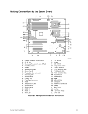
...Panel connector M. System Fan 3 P. HSBP B R. Battery V. PCI 32-bit/33 MHz AA. ICMB EE. NIC1 (10/100) FF. Main Power JJ. Primary Processor Socket (CPU1) B. Jumper Block CN43 O. HSBP A S. HDD LED OM14357 T. PCI-X 64-bit/100 MHz BB. System I . Aux Sig KK. +12 V CPU Power LL. Making Connections to the Server Board Server Board... installation 35 Jumper block CN53 X. CPU1 Fan Figure 20. IPMB N. PCI-X 64-bit/133 MHz Z. Making Connections to the Server Board II JJ KK LL HH A GG B FF...
...Panel connector M. System Fan 3 P. HSBP B R. Battery V. PCI 32-bit/33 MHz AA. ICMB EE. NIC1 (10/100) FF. Main Power JJ. Primary Processor Socket (CPU1) B. Jumper Block CN43 O. HSBP A S. HDD LED OM14357 T. PCI-X 64-bit/100 MHz BB. System I . Aux Sig KK. +12 V CPU Power LL. Making Connections to the Server Board Server Board... installation 35 Jumper block CN53 X. CPU1 Fan Figure 20. IPMB N. PCI-X 64-bit/133 MHz Z. Making Connections to the Server Board II JJ KK LL HH A GG B FF...

Product Guide
Page 37
Routing the Floppy and Front Panel Cables Cable Routing - Intel SC5200 Hot-Swap, Redundant Power Chassis Route the floppy drive cable and the hot-swap drive bay ICMB cable between the chassis wall and the hot-swap fan holder as shown. A A. Cable Routing Location OM14377 Figure 23. Routing the Floppy and ICMB Cables Server Board installation 37 Floppy Diskette Cable OM14376 Figure 22. A B A. Floppy and Front Panel Cables Route the floppy drive and front panel cables as shown below at location A. Front Panel Cable B.
Routing the Floppy and Front Panel Cables Cable Routing - Intel SC5200 Hot-Swap, Redundant Power Chassis Route the floppy drive cable and the hot-swap drive bay ICMB cable between the chassis wall and the hot-swap fan holder as shown. A A. Cable Routing Location OM14377 Figure 23. Routing the Floppy and ICMB Cables Server Board installation 37 Floppy Diskette Cable OM14376 Figure 22. A B A. Floppy and Front Panel Cables Route the floppy drive and front panel cables as shown below at location A. Front Panel Cable B.

Product Guide
Page 38
... 35 for the Serial B connector location. Installing the Serial B Cable 38 Intel Server Board SHG2 Product Guide Install the Serial B cable by inserting it into the chassis back panel cutout and attaching it to either the front (rack configuration only) or back panels. A B OM14557 A. Chassis Back Panel Cutout B. Screw Figure 24. Installing the Serial B Cable For the...
... 35 for the Serial B connector location. Installing the Serial B Cable 38 Intel Server Board SHG2 Product Guide Install the Serial B cable by inserting it into the chassis back panel cutout and attaching it to either the front (rack configuration only) or back panels. A B OM14557 A. Chassis Back Panel Cutout B. Screw Figure 24. Installing the Serial B Cable For the...

Product Guide
Page 39
... (10/100) J ICMB/External SCSI Connector Knockout* K Serial B Knockout* F Serial A * Intel SC5200 Base chassis shown here. Finishing Up WARNING An electrical shock hazard exists if the chassis cover is not replaced before connecting the chassis AC power. 1. Making Back Panel Connections Server Board installation 39 Item may be different on your chassis documentation to...
... (10/100) J ICMB/External SCSI Connector Knockout* K Serial B Knockout* F Serial A * Intel SC5200 Base chassis shown here. Finishing Up WARNING An electrical shock hazard exists if the chassis cover is not replaced before connecting the chassis AC power. 1. Making Back Panel Connections Server Board installation 39 Item may be different on your chassis documentation to...

Product Guide
Page 68
... that the BMC should wait before the BMC takes control. Click Close to return to save the changes. 8. A value of the server. 68 Intel Server Board SHG2 Product Guide The maximum value, 63, tells the BMC to ignore the call . Passwords can also clear the password by the DHCP ...(PEM). 2. • Restricted: a remote system can initiate a connection, but cannot perform control operations such as power down, reset, or front panel NMI. • Disabled: the remote system has full control of zero causes the BMC to answer immediately. Setting Up Remote Modem or Serial Access ...
... that the BMC should wait before the BMC takes control. Click Close to return to save the changes. 8. A value of the server. 68 Intel Server Board SHG2 Product Guide The maximum value, 63, tells the BMC to ignore the call . Passwords can also clear the password by the DHCP ...(PEM). 2. • Restricted: a remote system can initiate a connection, but cannot perform control operations such as power down, reset, or front panel NMI. • Disabled: the remote system has full control of zero causes the BMC to answer immediately. Setting Up Remote Modem or Serial Access ...

Product Guide
Page 79
... restart POST, and reload the operating system. Cold boot reset. Check the switches on the server board correct? q Are all jumper and switch settings on the Intel Customer Support website. 79 5 Solving Problems This chapter helps you identify and solve problems that ...might occur while you press the system power on/off switch on the front panel to turn the server on (power on light should be lit)? Checklist q Are the power supplies turned on the server board...
... restart POST, and reload the operating system. Cold boot reset. Check the switches on the server board correct? q Are all jumper and switch settings on the Intel Customer Support website. 79 5 Solving Problems This chapter helps you identify and solve problems that ...might occur while you press the system power on/off switch on the front panel to turn the server on (power on light should be lit)? Checklist q Are the power supplies turned on the server board...

Product Guide
Page 82
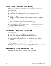
...are correct and problems persist, contact your service representative or authorized dealer for help . 82 Intel Server Board SHG2 Product Guide If so, the power LED may be defective or the cable from the front panel to the operating system. q Are there other problems with application software • The ...prompt appears on briefly? If not, see "Diskette Drive Activity Light Does Not Light" on briefly. The prompt varies according to the server board is not detected Try the solutions in the system. If so, check the items listed under "System Cooling Fans Do Not Rotate ...
...are correct and problems persist, contact your service representative or authorized dealer for help . 82 Intel Server Board SHG2 Product Guide If so, the power LED may be defective or the cable from the front panel to the operating system. q Are there other problems with application software • The ...prompt appears on briefly? If not, see "Diskette Drive Activity Light Does Not Light" on briefly. The prompt varies according to the server board is not detected Try the solutions in the system. If so, check the items listed under "System Cooling Fans Do Not Rotate ...
Product Guide
Page 84
... of the fan motors stopped (use the Setup Utility to make sure that "Onboard Floppy" is not connected to the SHG2 server board. 84 Intel Server Board SHG2 Product Guide If the switches and connections are using an add-in incorrectly. q Have any shorted wires caused by pinched ...could be a problem with the diskette drive, server board, or drive signal cable. q Is the cable from the front panel board connected to the server board? If you press the power button? q Are the fan power connectors properly connected to the server board? Check the following : q Are the diskette...
... of the fan motors stopped (use the Setup Utility to make sure that "Onboard Floppy" is not connected to the SHG2 server board. 84 Intel Server Board SHG2 Product Guide If the switches and connections are using an add-in incorrectly. q Have any shorted wires caused by pinched ...could be a problem with the diskette drive, server board, or drive signal cable. q Is the cable from the front panel board connected to the server board? If you press the power button? q Are the fan power connectors properly connected to the server board? Check the following : q Are the diskette...
Product Guide
Page 85
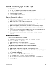
...If the cable is current. q Check the network controller LEDs that needs to the connector at the system back panel. q Make sure the cable is connected to a Server q Make sure you specify the correct frame type in adapter. then try a different cable. Delete and then reinstall... q Change the PCI BIOS interrupt settings. q Make sure your LAN administrator about the correct networking software that are directly connecting two servers (no hub), you will need a crossover cable (see your hub documentation for the onboard network controller. Cannot Connect to the port...
...If the cable is current. q Check the network controller LEDs that needs to the connector at the system back panel. q Make sure the cable is connected to a Server q Make sure you specify the correct frame type in adapter. then try a different cable. Delete and then reinstall... q Change the PCI BIOS interrupt settings. q Make sure your LAN administrator about the correct networking software that are directly connecting two servers (no hub), you will need a crossover cable (see your hub documentation for the onboard network controller. Cannot Connect to the port...
Product Guide
Page 90
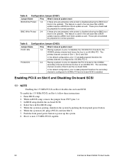
...jumpered, write protect is now 133 MHz PCI-X capable. 90 Intel Server Board SHG2 Product Guide Enter BIOS setup. 2. These pins should not be updated. The secondary channel consists of Slot 1, Slot 2 and Gbit. Enabling PCI-X on Slot 6 and Disabling On-board SCSI ✏ NOTE Enabling the 133 MHz PCI-X on Slot...well. Slot 6 is disabled allowing the BMC boot block to be jumpered for 66 MHz PCI and on-board SCSI is posting, shutdown the system by pushing the front panel power button. 6. These pins should not be updated. While the system in BIOS setup, remove the jumper...
...jumpered, write protect is now 133 MHz PCI-X capable. 90 Intel Server Board SHG2 Product Guide Enter BIOS setup. 2. These pins should not be updated. The secondary channel consists of Slot 1, Slot 2 and Gbit. Enabling PCI-X on Slot 6 and Disabling On-board SCSI ✏ NOTE Enabling the 133 MHz PCI-X on Slot...well. Slot 6 is disabled allowing the BMC boot block to be jumpered for 66 MHz PCI and on-board SCSI is posting, shutdown the system by pushing the front panel power button. 6. These pins should not be updated. While the system in BIOS setup, remove the jumper...
Product Guide
Page 97
...Panel Connectors, 10 battery disposing of safely, 52 installing, 53 removing, 52 beep codes, 56 BIOS changing the language, 75 recovering, 75 updates, 63 upgrading, 73 boot sequence booting without keyboard, 20 setting in Setup, 20 bootable media, required by POST, 56 booting cold, 79 booting the server... drive, 57 saving and restoring, 64 CN42 pins, 75 configuration, limiting access to system with administrative password, 20 configuring server board jumpers location on server board, 87, 89 configuring system SCU, 55 Setup, 55 Connector, USB, 14 controller keyboard/mouse, 17 network, 9, 15...
...Panel Connectors, 10 battery disposing of safely, 52 installing, 53 removing, 52 beep codes, 56 BIOS changing the language, 75 recovering, 75 updates, 63 upgrading, 73 boot sequence booting without keyboard, 20 setting in Setup, 20 bootable media, required by POST, 56 booting cold, 79 booting the server... drive, 57 saving and restoring, 64 CN42 pins, 75 configuration, limiting access to system with administrative password, 20 configuring server board jumpers location on server board, 87, 89 configuring system SCU, 55 Setup, 55 Connector, USB, 14 controller keyboard/mouse, 17 network, 9, 15...


