Product Guide
Page 3
... Locations 11 Processor ...12 Memory ...12 Add-in Board Connectors ...13 Video ...13 SCSI Controller ...14 Modular RAID Capable PCI-X Slot 6 14 IDE Controller...14 USB Interface ...14 Network Controllers...15 Network Teaming Features 15 Keyboard and Mouse ...17 ACPI...17 Security ...17 Security with Intel® Server Management and Intel® SMaRT Tool (Optional) ....40 iii Intel SC5200 Hot-Swap, Redundant Power Chassis 37 Installing the Serial B Cable 38 Finishing Up...39 Getting Started with Mechanical Locks and Monitoring 17 Software...
... Locations 11 Processor ...12 Memory ...12 Add-in Board Connectors ...13 Video ...13 SCSI Controller ...14 Modular RAID Capable PCI-X Slot 6 14 IDE Controller...14 USB Interface ...14 Network Controllers...15 Network Teaming Features 15 Keyboard and Mouse ...17 ACPI...17 Security ...17 Security with Intel® Server Management and Intel® SMaRT Tool (Optional) ....40 iii Intel SC5200 Hot-Swap, Redundant Power Chassis 37 Installing the Serial B Cable 38 Finishing Up...39 Getting Started with Mechanical Locks and Monitoring 17 Software...
Product Guide
Page 12
... to run even in the event of a multi-bit SDRAM failure. The memory controller supports 2-way interleaved SDRAM, memory scrubbing, single-bit error correction and multiple-bit error detection with Chipkill† capability that have been tested for compatibility with 512 KB of supported processors, see: http://support.intel.com/support/motherboards/server/SHG2 Memory The Intel Server Board SHG2 contains six 184-pin DIMM sockets. For a complete list of L2 advanced transfer cache packaged in a 603...
... to run even in the event of a multi-bit SDRAM failure. The memory controller supports 2-way interleaved SDRAM, memory scrubbing, single-bit error correction and multiple-bit error detection with Chipkill† capability that have been tested for compatibility with 512 KB of supported processors, see: http://support.intel.com/support/motherboards/server/SHG2 Memory The Intel Server Board SHG2 contains six 184-pin DIMM sockets. For a complete list of L2 advanced transfer cache packaged in a 603...
Product Guide
Page 14
...://support.intel.com/support/motherboards/server/SHG2 IDE Controller The system includes a dual-channel enhanced IDE 32-bit interface controller for both SCSI channels. If a specified modular RAID card is supported internally through a 10-pin header on the server board that can be cabled to a front panel board. For a complete list of qualified add-in cards, see "Enabling PCI-X on Slot 6 and Disabling On-board SCSI" on PCI-X Slot 6. All four ports function identically and with its own built-in this slot leverages the onboard SCSI controller along...
...://support.intel.com/support/motherboards/server/SHG2 IDE Controller The system includes a dual-channel enhanced IDE 32-bit interface controller for both SCSI channels. If a specified modular RAID card is supported internally through a 10-pin header on the server board that can be cabled to a front panel board. For a complete list of qualified add-in cards, see "Enabling PCI-X on Slot 6 and Disabling On-board SCSI" on PCI-X Slot 6. All four ports function identically and with its own built-in this slot leverages the onboard SCSI controller along...

Product Guide
Page 17
... entry or use of time. ACPI The SHG2 supports the Advanced Configuration and Power Interface (ACPI) as defined by locking the keyboard, for a predefined length of the server, Intel® Server Management software monitors the system intrusion switch. CAUTION The system is off : Only the real time clock (RTC) section of the chipset and the Baseboard Management Controller (BMC) are saved to disk. Description 17 However, the power supply will...
... entry or use of time. ACPI The SHG2 supports the Advanced Configuration and Power Interface (ACPI) as defined by locking the keyboard, for a predefined length of the server, Intel® Server Management software monitors the system intrusion switch. CAUTION The system is off : Only the real time clock (RTC) section of the chipset and the Baseboard Management Controller (BMC) are saved to disk. Description 17 However, the power supply will...
Product Guide
Page 18
... user password to enter BIOS Setup or the SSU. • Must enter the user password to boot the server if Password on Boot is set. • Disable access to exit secure mode. For example: • Enable the keyboard lockout timer so that the server requires a password to exit secure mode. 18 Intel Server Board SHG2 Product Guide Software Locks The BIOS Setup and the System Setup Utility (SSU) provide a number of security features to prevent unauthorized or accidental access to exit secure mode. Using Passwords...
... user password to enter BIOS Setup or the SSU. • Must enter the user password to boot the server if Password on Boot is set. • Disable access to exit secure mode. For example: • Enable the keyboard lockout timer so that the server requires a password to exit secure mode. 18 Intel Server Board SHG2 Product Guide Software Locks The BIOS Setup and the System Setup Utility (SSU) provide a number of security features to prevent unauthorized or accidental access to exit secure mode. Using Passwords...
Product Guide
Page 19
... have to use the Setup main menu, Floppy Options, and specify Floppy Access as read only. Summary of system power. All enabled secure mode features go to a diskette unless a password is entered. Secure mode has no CD in the CD-ROM drive or diskette in effect, the system will not boot from CD or diskette and disables the secure mode. Secure Mode Configure and enable the secure boot mode by pressing the key combination. This...
... have to use the Setup main menu, Floppy Options, and specify Floppy Access as read only. Summary of system power. All enabled secure mode features go to a diskette unless a password is entered. Secure mode has no CD in the CD-ROM drive or diskette in effect, the system will not boot from CD or diskette and disables the secure mode. Secure Mode Configure and enable the secure boot mode by pressing the key combination. This...
Product Guide
Page 20
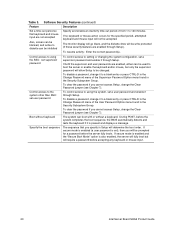
... be blanked, and writes to diskette can be inhibited Specify and enable an inactivity time-out period of the User Password Option menu found in Setup will be accepted. To clear the password if you cannot access Setup, change the Clear Password jumper (see Chapter 7). During POST, before accepting any keyboard or mouse input. 20 Intel Server Board SHG2 Product Guide If secure mode is enabled and the "Secure Boot Mode" option is set a user password and enable it through Setup).
... be blanked, and writes to diskette can be inhibited Specify and enable an inactivity time-out period of the User Password Option menu found in Setup will be accepted. To clear the password if you cannot access Setup, change the Clear Password jumper (see Chapter 7). During POST, before accepting any keyboard or mouse input. 20 Intel Server Board SHG2 Product Guide If secure mode is enabled and the "Secure Boot Mode" option is set a user password and enable it through Setup).
Product Guide
Page 26
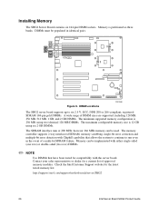
Installing Memory The SHG2 Server Board contains six 184-pin DIMM sockets. The memory controller supports 2-way interleaved SDRAM, memory scrubbing, single-bit error correction and multiple-bit error detection with the server board. Contact your sales representative or dealer for a current list of a multi-bit SDRAM failure. DIMMs must be implemented with either single-sided (one row) or double-sided (two row) DIMMs. ✏ NOTE Use DIMMs that allows the system...
Installing Memory The SHG2 Server Board contains six 184-pin DIMM sockets. The memory controller supports 2-way interleaved SDRAM, memory scrubbing, single-bit error correction and multiple-bit error detection with the server board. Contact your sales representative or dealer for a current list of a multi-bit SDRAM failure. DIMMs must be implemented with either single-sided (one row) or double-sided (two row) DIMMs. ✏ NOTE Use DIMMs that allows the system...
Product Guide
Page 44
... range of a multi-bit SDRAM failure. The memory controller supports 2-way interleaved SDRAM, memory scrubbing, single-bit error correction and multiple-bit error detection with either single-sided (one row) or double-sided (two row) DIMMs. ✏ NOTE Use DIMMs that allows the system to continue to remove or install a jumper; Memory The SHG2 Server Board contains six 184-pin DIMM sockets. DIMMs must be used. Installing or removing jumpers: A jumper is a small plastic encased...
... range of a multi-bit SDRAM failure. The memory controller supports 2-way interleaved SDRAM, memory scrubbing, single-bit error correction and multiple-bit error detection with either single-sided (one row) or double-sided (two row) DIMMs. ✏ NOTE Use DIMMs that allows the system to continue to remove or install a jumper; Memory The SHG2 Server Board contains six 184-pin DIMM sockets. DIMMs must be used. Installing or removing jumpers: A jumper is a small plastic encased...

Product Guide
Page 56
... for your video monitor and server. Also see the "Monitoring POST" on the system, POST starts running , it is able to enter SCSI Utility 4. Note the screen display and write down the beep code you turn on page 81. 56 Intel Server Board SHG2 Product Guide Power-On Self-Test (POST) Each time you hear; If POST can generate, see "Using the Adaptec SCSI Utility" on your service representative. Press if there are SCSI devices installed. this...
... for your video monitor and server. Also see the "Monitoring POST" on the system, POST starts running , it is able to enter SCSI Utility 4. Note the screen display and write down the beep code you turn on page 81. 56 Intel Server Board SHG2 Product Guide Power-On Self-Test (POST) Each time you hear; If POST can generate, see "Using the Adaptec SCSI Utility" on your service representative. Press if there are SCSI devices installed. this...
Product Guide
Page 57
... set diskette drive options, and change the jumper back. This will see the message, press the key while the splash screen is hidden by the Manufacturer's Splash screen. You can enter and start Setup under the heading, "CMOS Jumper." POST uses these values to see Chapter 5, under several conditions: • When you turn on a worksheet. If You Cannot Access Setup If the diskette drive is enabled (Default), you must then run Setup...
... set diskette drive options, and change the jumper back. This will see the message, press the key while the splash screen is hidden by the Manufacturer's Splash screen. You can enter and start Setup under the heading, "CMOS Jumper." POST uses these values to see Chapter 5, under several conditions: • When you turn on a worksheet. If You Cannot Access Setup If the diskette drive is enabled (Default), you must then run Setup...
Product Guide
Page 59
The mouse driver loads if it is available; Configuration Software and Utilities 59 Running the SSU When the SSU starts in a list, such as screen colors). If you cannot save user preference settings (such as the Available Tasks list. The SSU supports ROM-DOS version 6.22. Start the SSU using one of from read-only media, such as the CD-ROM, you run a list item, such as one of...
The mouse driver loads if it is available; Configuration Software and Utilities 59 Running the SSU When the SSU starts in a list, such as screen colors). If you cannot save user preference settings (such as the Available Tasks list. The SSU supports ROM-DOS version 6.22. Start the SSU using one of from read-only media, such as the CD-ROM, you run a list item, such as one of...
Product Guide
Page 63
.... When you can update the BIOS, update the firmware, and verify the firmware. Updating System Firmware and BIOS Using the SSU, you start System Update, it automatically loads the SDR entries from the Intel support website: http://support.intel.com/support/motherboards/server/SHG2 Updating the BIOS To update the BIOS: 1. From the SSU Main window, choose SDR Manager. From the File menu, choose Load and choose a .uif or .bio file to update the BIOS. Use the File and SDR menu items to work with the SDR...
.... When you can update the BIOS, update the firmware, and verify the firmware. Updating System Firmware and BIOS Using the SSU, you start System Update, it automatically loads the SDR entries from the Intel support website: http://support.intel.com/support/motherboards/server/SHG2 Updating the BIOS To update the BIOS: 1. From the SSU Main window, choose SDR Manager. From the File menu, choose Load and choose a .uif or .bio file to update the BIOS. Use the File and SDR menu items to work with the SDR...
Product Guide
Page 75
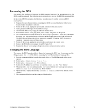
... beeps will sound and the floppy drive access light will interrupt the BIOS upgrade; Power off the system. 7. Replace the chassis' cover, plug in the power cord(s), and power on CN43 pins 9-10 (BIOS recovery). 4. Select Update Flash Memory From a File. 3. Select drive A and use the BIOS upgrade utility to change the language the BIOS uses for messages and the Setup program. Press . 6. Prepare a bootable floppy diskette containing the BIOS recovery files for confirmation that anything will turn off the system, unplug the power cord, and remove...
... beeps will sound and the floppy drive access light will interrupt the BIOS upgrade; Power off the system. 7. Replace the chassis' cover, plug in the power cord(s), and power on CN43 pins 9-10 (BIOS recovery). 4. Select Update Flash Memory From a File. 3. Select drive A and use the BIOS upgrade utility to change the language the BIOS uses for messages and the Setup program. Press . 6. Prepare a bootable floppy diskette containing the BIOS recovery files for confirmation that anything will turn off the system, unplug the power cord, and remove...
Product Guide
Page 76
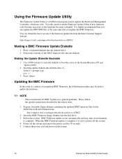
... the BMC Firmware floppy diskette into diskette drive A. Connect the power cord and power on the system. 76 Intel Server Board SHG2 Product Guide It is safe to update the firmware. ✏ NOTE These instructions for BMC Update are a general guideline. You can obtain the latest version of the firmware update file from : http://support.intel.com/support/motherboards/server/SHG2 2. Place a formatted diskette into the diskette drive. 2. Use a DOS system to create the diskette or boot the server to...
... the BMC Firmware floppy diskette into diskette drive A. Connect the power cord and power on the system. 76 Intel Server Board SHG2 Product Guide It is safe to update the firmware. ✏ NOTE These instructions for BMC Update are a general guideline. You can obtain the latest version of the firmware update file from : http://support.intel.com/support/motherboards/server/SHG2 2. Place a formatted diskette into the diskette drive. 2. Use a DOS system to create the diskette or boot the server to...
Product Guide
Page 84
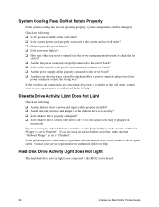
... the server board? q Are all relevant switches and jumpers on the diskette drive set to "Enabled". q Is the diskette drive properly configured? If the problem persists, there may be plugged in diskette controller, make sure that "Onboard Floppy" is set to make sure that "Onboard Floppy" is set correctly? q Is the power on ? q Is the cable from the front panel board connected to the server board? q Are there any of the fan motors stopped (use the Setup Utility to "Disabled...
... the server board? q Are all relevant switches and jumpers on the diskette drive set to "Enabled". q Is the diskette drive properly configured? If the problem persists, there may be plugged in diskette controller, make sure that "Onboard Floppy" is set to make sure that "Onboard Floppy" is set correctly? q Is the power on ? q Is the cable from the front panel board connected to the server board? q Are there any of the fan motors stopped (use the Setup Utility to "Disabled...
Product Guide
Page 85
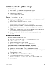
... network controller LEDs that are shipped on the system Configuration Software CD for the onboard network controller. Problems with your LAN administrator about the correct networking software that needs to the connector at the system back panel. The controller stopped working without apparent cause. Delete and then reinstall the drivers. q Is the onboard IDE controller enabled? q Make sure the network cable is securely attached to be corrupt or deleted. If the cable is connected to a Server...
... network controller LEDs that are shipped on the system Configuration Software CD for the onboard network controller. Problems with your LAN administrator about the correct networking software that needs to the connector at the system back panel. The controller stopped working without apparent cause. Delete and then reinstall the drivers. q Is the onboard IDE controller enabled? q Make sure the network cable is securely attached to be corrupt or deleted. If the cable is connected to a Server...
Product Guide
Page 90
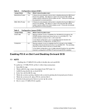
... Intel Server Board SHG2 Product Guide BMC Write Protect 3-4 If these pins are jumpered, write protect is configured for normal operation. Configuration Jumper (CN27) Jumper Name Pins What it does at system reset BIOS Write Protect 1-2 If these instructions: 1. This feature is enabled. The primary channel consists of Slot 6 and the on Slot 6, follow these pins are jumpered, write protect is disabled allowing the BMC boot block to power up the system. 8. Enabling PCI-X on Slot 6 and Disabling...
... Intel Server Board SHG2 Product Guide BMC Write Protect 3-4 If these pins are jumpered, write protect is configured for normal operation. Configuration Jumper (CN27) Jumper Name Pins What it does at system reset BIOS Write Protect 1-2 If these instructions: 1. This feature is enabled. The primary channel consists of Slot 6 and the on Slot 6, follow these pins are jumpered, write protect is disabled allowing the BMC boot block to power up the system. 8. Enabling PCI-X on Slot 6 and Disabling...
Product Guide
Page 97
... correct processor, 45, 52 controller, video, 13 CMOS clear to reconfigure diskette drive, 57 saving and restoring, 64 CN42 pins, 75 configuration, limiting access to system with administrative password, 20 configuring server board jumpers location on server board, 87, 89 configuring system SCU, 55 Setup, 55 Connector, USB, 14 controller keyboard/mouse, 17 network, 9, 15 SCSI, 14 video, 9 IDE, 14 Memory, 12, 26, 44, 45 D diagnostics, preparing system for testing, 81 DIMM, 12, 26, 44, 45 diskette enabling/disabling floppy...
... correct processor, 45, 52 controller, video, 13 CMOS clear to reconfigure diskette drive, 57 saving and restoring, 64 CN42 pins, 75 configuration, limiting access to system with administrative password, 20 configuring server board jumpers location on server board, 87, 89 configuring system SCU, 55 Setup, 55 Connector, USB, 14 controller keyboard/mouse, 17 network, 9, 15 SCSI, 14 video, 9 IDE, 14 Memory, 12, 26, 44, 45 D diagnostics, preparing system for testing, 81 DIMM, 12, 26, 44, 45 diskette enabling/disabling floppy...
Product Guide
Page 98
... G-J GUI, working with, 59 heat sink, fan, 46, 52 hot key option, quick reference, 55 I/O PCI expansion slots, 9 ports provided, 9 IDE, feature summary, 13 IDE controller, 14 intrusion detection, 17 jumpers, do not damage when changing, 44 K-L keyboard compatibility, 17 lockout timer, seting in SCU, 17 LAN alerts, 66 LAN remote access, 67 language, changing in BIOS, 75 lithium backup battery disposing of safely, 52 installing, 53 removing, 52 M-N memory amount tested, POST, 56 capacity...
... G-J GUI, working with, 59 heat sink, fan, 46, 52 hot key option, quick reference, 55 I/O PCI expansion slots, 9 ports provided, 9 IDE, feature summary, 13 IDE controller, 14 intrusion detection, 17 jumpers, do not damage when changing, 44 K-L keyboard compatibility, 17 lockout timer, seting in SCU, 17 LAN alerts, 66 LAN remote access, 67 language, changing in BIOS, 75 lithium backup battery disposing of safely, 52 installing, 53 removing, 52 M-N memory amount tested, POST, 56 capacity...


