
Product Specification
Page 6
...) 129 vi Revision 1.0 Intel order number D24635-001 Server Board SE7320EP2 and SE7525RP2 Connectors 104 10.1 Main Power Connector 104 10.2 Memory Module Connector 105 10.3 Processor Socket 107 10.4 I2C Header ...110 10.5 PCI Slot Connector 111 10.6 Front Panel Connector 114 10.7 VGA Connector...115 10.8 NIC Connector ...115 10.9 IDE Connector ...116 10.10 SATA Connector 116 10.11...
...) 129 vi Revision 1.0 Intel order number D24635-001 Server Board SE7320EP2 and SE7525RP2 Connectors 104 10.1 Main Power Connector 104 10.2 Memory Module Connector 105 10.3 Processor Socket 107 10.4 I2C Header ...110 10.5 PCI Slot Connector 111 10.6 Front Panel Connector 114 10.7 VGA Connector...115 10.8 NIC Connector ...115 10.9 IDE Connector ...116 10.10 SATA Connector 116 10.11...

Product Specification
Page 10
...604 Processor Socket Pin-out (J36, J37 107 Table 73. Front Panel 34-Pin Header Pin-out (J38 114 Table 79. Voltage Timing Parameters 124 Table 98. List of Tables Intel® Server Board SE7320EP2 / Intel® Server Board SE7525RP2 Table 68. SATA Connector Pin-out (J28, J32 116 Table 83. P32-A 5V 32-...bit/33-MHz PCI Slot Pin-out (J10, J11 111 Table 76. P64-B 3.3V 64-bit/66-MHz PCI-X Slot Pin-out (J8, J9 112 Table 77. VGA Connector ...
...604 Processor Socket Pin-out (J36, J37 107 Table 73. Front Panel 34-Pin Header Pin-out (J38 114 Table 79. Voltage Timing Parameters 124 Table 98. List of Tables Intel® Server Board SE7320EP2 / Intel® Server Board SE7525RP2 Table 68. SATA Connector Pin-out (J28, J32 116 Table 83. P32-A 5V 32-...bit/33-MHz PCI Slot Pin-out (J10, J11 111 Table 76. P64-B 3.3V 64-bit/66-MHz PCI-X Slot Pin-out (J8, J9 112 Table 77. VGA Connector ...

Product Specification
Page 12
...Intel® E7320/E7525 chipset and is capable of memory. 2.1 Intel® Server Boards SE7320EP2 and SE7525RP2 Feature Set The Intel Server Boards SE7320EP2 and SE7525RP2 support the following feature set: ƒ Processor/FSB support - Segment A: Two PCI 32-bit/33-MHz, 5 V connectors...Support for front panel support 12 Revision 1.0 Intel order number D24635-001 One version 10.1 compliant VRD to support the general purpose, pedestal server market. Intel® Server Board SE7320EP2 / SE7525RP2 Overview The Intel® Server Boards SE7320EP2 and SE7525RP2 are monolithic printed...
...Intel® E7320/E7525 chipset and is capable of memory. 2.1 Intel® Server Boards SE7320EP2 and SE7525RP2 Feature Set The Intel Server Boards SE7320EP2 and SE7525RP2 support the following feature set: ƒ Processor/FSB support - Segment A: Two PCI 32-bit/33-MHz, 5 V connectors...Support for front panel support 12 Revision 1.0 Intel order number D24635-001 One version 10.1 compliant VRD to support the general purpose, pedestal server market. Intel® Server Board SE7320EP2 / SE7525RP2 Overview The Intel® Server Boards SE7320EP2 and SE7525RP2 are monolithic printed...
Product Specification
Page 13
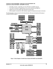
... up to two SATA devices and RAID 0/1 ƒ Support for up to five system fans and two processor fans ƒ SSI-compliant connectors for SSI interface support: front panel and power connectors The following figure below shows the functional blocks of Intel® Server Boards SE7320EP2 and SE7525RP2 Revision 1.0 13 Intel order number D24635-001 Figure 1.
... up to two SATA devices and RAID 0/1 ƒ Support for up to five system fans and two processor fans ƒ SSI-compliant connectors for SSI interface support: front panel and power connectors The following figure below shows the functional blocks of Intel® Server Boards SE7320EP2 and SE7525RP2 Revision 1.0 13 Intel order number D24635-001 Figure 1.
Product Specification
Page 23
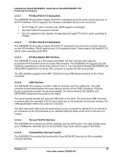
... each (drives 0 and 1). The dual-stack USB connector is located within the standard ATX I /O transfers and bus master IDE transfers. Intel® Server Board SE7320EP2 / Intel® Server Board SE7525RP2 TPS Functional Architecture 3.2.3.1 PCI Bus P32-A I/O Subsystem...SE7525RP2 implement four ports on the back. The IDE interface supports Ultra DMA 100 Synchronous DMA Mode transfers on the server boards to an external USB port either at 66 MHz. 3.2.3.3 PCI Bus Master IDE Interface The 6300ESB ICH acts as a PCI-based Ultra DMA 100 IDE controller that supports programmed I /O panel...
... each (drives 0 and 1). The dual-stack USB connector is located within the standard ATX I /O transfers and bus master IDE transfers. Intel® Server Board SE7320EP2 / Intel® Server Board SE7525RP2 TPS Functional Architecture 3.2.3.1 PCI Bus P32-A I/O Subsystem...SE7525RP2 implement four ports on the back. The IDE interface supports Ultra DMA 100 Synchronous DMA Mode transfers on the server boards to an external USB port either at 66 MHz. 3.2.3.3 PCI Bus Master IDE Interface The 6300ESB ICH acts as a PCI-based Ultra DMA 100 IDE controller that supports programmed I /O panel...
Product Specification
Page 27
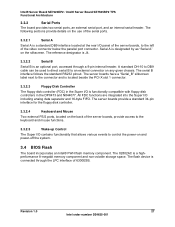
...1.0 27 Intel order number D24635-001 The following sections provide details on the use of the serial ports. 3.3.2.1 Serial A Serial A is functionally compatible with floppy disk controllers in the Super I/O is a standard DB9 interface located at the rear I/O panel of the ...a "Serial_B" silkscreen label next to an external connector on and power-off the system. 3.4 BIOS Flash The board incorporates an Intel® FWH flash memory component. Intel® Server Board SE7320EP2 / Intel® Server Board SE7525RP2 TPS Functional Architecture 3.3.2 Serial Ports The board provides...
...1.0 27 Intel order number D24635-001 The following sections provide details on the use of the serial ports. 3.3.2.1 Serial A Serial A is functionally compatible with floppy disk controllers in the Super I/O is a standard DB9 interface located at the rear I/O panel of the ...a "Serial_B" silkscreen label next to an external connector on and power-off the system. 3.4 BIOS Flash The board incorporates an Intel® FWH flash memory component. Intel® Server Board SE7320EP2 / Intel® Server Board SE7525RP2 TPS Functional Architecture 3.3.2 Serial Ports The board provides...

Product Specification
Page 114
...SDA SMB SCL *INDRUDER NIC2 ACT_LED NIC2 ACT_LED# Key NC NC NC NC 114 Revision 1.0 Intel order number D24635-001 Intel® Server Board SE7320EP2 / Intel® Server Board SE7525RP2 TPS Server Board SE7320EP2 and SE7525RP2 Connectors Pin Side B Side A End of this header. The following table details the pin-out... HSON15 80 GND 81 RSVD 82 RSVD Side A GND GND HSIP14 HSIN14 GND GND HSIP15 HSIN15 GND 10.6 Front Panel Connector A standard SSI 34-pin header is provided to support a system front panel. The header contains reset, NMI, power control buttons, and LED indicators.
...SDA SMB SCL *INDRUDER NIC2 ACT_LED NIC2 ACT_LED# Key NC NC NC NC 114 Revision 1.0 Intel order number D24635-001 Intel® Server Board SE7320EP2 / Intel® Server Board SE7525RP2 TPS Server Board SE7320EP2 and SE7525RP2 Connectors Pin Side B Side A End of this header. The following table details the pin-out... HSON15 80 GND 81 RSVD 82 RSVD Side A GND GND HSIP14 HSIN14 GND GND HSIP15 HSIN15 GND 10.6 Front Panel Connector A standard SSI 34-pin header is provided to support a system front panel. The header contains reset, NMI, power control buttons, and LED indicators.
Quick Start Guide
Page 1
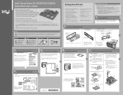
... • . • 4* .... -... 1 00. .....• a. Chassis Back Panel Opening O Insert one Intel® Xeonm processor with the Intel® Server Boards SE7525RP2 and SE7320EP2. For the Intel Entry Server Chassis SC5295WS with either the Server Board SE7320EP2 or SE7525RP2, a minimum 500W power supply is located on a label on board and chassis...1. 2. E. N o.4000% C. Insert the front of the board first, then slide the board back so the I/O connectors fit through the matching holes around the heat sink in this step if you must be claimed as shown. Connect Heat Sink...
... • . • 4* .... -... 1 00. .....• a. Chassis Back Panel Opening O Insert one Intel® Xeonm processor with the Intel® Server Boards SE7525RP2 and SE7320EP2. For the Intel Entry Server Chassis SC5295WS with either the Server Board SE7320EP2 or SE7525RP2, a minimum 500W power supply is located on a label on board and chassis...1. 2. E. N o.4000% C. Insert the front of the board first, then slide the board back so the I/O connectors fit through the matching holes around the heat sink in this step if you must be claimed as shown. Connect Heat Sink...


