
User Guide
Page 3
... the password or CMOS. Manual Organization Chapter 1 provides a brief overview of these products. ✏ NOTES Most diagrams in the Intel® Server Board SE7520BD2 Technical Product Specification. For the latest version of this server board are responsible for troubleshooting, upgrading, and ...accessories or other components. Use this chapter for step-bystep instructions and diagrams for installing or replacing components such as the memory, processor, and the battery, among other components you identify components and their locations. In this chapter, you will find a list ...
... the password or CMOS. Manual Organization Chapter 1 provides a brief overview of these products. ✏ NOTES Most diagrams in the Intel® Server Board SE7520BD2 Technical Product Specification. For the latest version of this server board are responsible for troubleshooting, upgrading, and ...accessories or other components. Use this chapter for step-bystep instructions and diagrams for installing or replacing components such as the memory, processor, and the battery, among other components you identify components and their locations. In this chapter, you will find a list ...
User Guide
Page 4
... Reference Chassis List iv Preface Product Accessories These server boards are compatible with the following accessory items for your server: ƒ Processor ƒ Memory DIMM ƒ Hard drive ƒ Floppy drive/CD-ROM drive/DVD-ROM drive ƒ RAID controller ƒ... with this server board, use this document / software Intel® Server Board SE7520BD2 Technical Product Specification Intel® Server Board SE7520BD2 Quick Start User's Guide located in -depth technical information about which accessories, memory, processors, and third-party hardware have the right server board ...
... Reference Chassis List iv Preface Product Accessories These server boards are compatible with the following accessory items for your server: ƒ Processor ƒ Memory DIMM ƒ Hard drive ƒ Floppy drive/CD-ROM drive/DVD-ROM drive ƒ RAID controller ƒ... with this server board, use this document / software Intel® Server Board SE7520BD2 Technical Product Specification Intel® Server Board SE7520BD2 Quick Start User's Guide located in -depth technical information about which accessories, memory, processors, and third-party hardware have the right server board ...
User Guide
Page 5
... computer integration, make sure your system falls within the allowed power budget For software to manage your Intel® Server For firmware, BIOS updates, and drivers Supported Processor List Tested Memory List Power Budget Tool Intel® Server Management Software Download Finder To obtain the documents or software mentioned in this guide. Integration...
... computer integration, make sure your system falls within the allowed power budget For software to manage your Intel® Server For firmware, BIOS updates, and drivers Supported Processor List Tested Memory List Power Budget Tool Intel® Server Management Software Download Finder To obtain the documents or software mentioned in this guide. Integration...
User Guide
Page 9
..., SE7520BD2VD2, SE7520BD2SATAD2 20 Configuration Jumpers ...22 Back Panel Connectors...23 Hardware Requirements ...24 Server Chassis ...24 Processor ...24 Memory ...25 2 Hardware Installations and Upgrades 28 Before You Begin ...28 Tools and Supplies Needed ...Installing and Removing Memory 28 Installing DIMMs...29 Removing DIMMs...30 Installing or Replacing the Processor 30 Installing the Processor 31 Removing a Processor 34 Installing or Removing a PCI Card 34 Replacing the Backup Battery 35 3 Server... 48 Power Light Does Not Light 48 Intel® Server Board SE7520BD2 User Guide ix
..., SE7520BD2VD2, SE7520BD2SATAD2 20 Configuration Jumpers ...22 Back Panel Connectors...23 Hardware Requirements ...24 Server Chassis ...24 Processor ...24 Memory ...25 2 Hardware Installations and Upgrades 28 Before You Begin ...28 Tools and Supplies Needed ...Installing and Removing Memory 28 Installing DIMMs...29 Removing DIMMs...30 Installing or Replacing the Processor 30 Installing the Processor 31 Removing a Processor 34 Installing or Removing a PCI Card 34 Replacing the Backup Battery 35 3 Server... 48 Power Light Does Not Light 48 Intel® Server Board SE7520BD2 User Guide ix
User Guide
Page 11
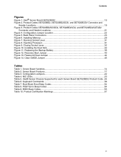
... 7. Clear CMOS Jumper 45 Tables Table 1. NIC LEDs ...23 Table 5. Product Certification Markings 57 xi Contents Figures Figure 1. Intel® Server Board SE7520BD2 13 Figure 2. Product Codes SE7520BD2SCSID2, SE7520BD2VD2, and SE7520BD2SATAD2 Connector and Header Locations 21 Figure 4. Closing ...Figure 12. Opening Socket Lever 31 Figure 8. Server Board Features 17 Table 3. Intel® Server Chassis Supported for each Server Board SE7520BD2 Product Code.. 24 Table 6. Inserting Processor...31 Figure 9. Configuration Jumpers 22 Table 4. Back Panel Connectors 23 Figure 6....
... 7. Clear CMOS Jumper 45 Tables Table 1. NIC LEDs ...23 Table 5. Product Certification Markings 57 xi Contents Figures Figure 1. Intel® Server Board SE7520BD2 13 Figure 2. Product Codes SE7520BD2SCSID2, SE7520BD2VD2, and SE7520BD2SATAD2 Connector and Header Locations 21 Figure 4. Closing ...Figure 12. Opening Socket Lever 31 Figure 8. Server Board Features 17 Table 3. Intel® Server Chassis Supported for each Server Board SE7520BD2 Product Code.. 24 Table 6. Inserting Processor...31 Figure 9. Configuration Jumpers 22 Table 4. Back Panel Connectors 23 Figure 6....
User Guide
Page 17
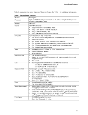
... 12 inches by 13 inches 17 Table 2. Server Board Features Table 2 summarizes the major features of critical sensor information. ƒ Intel® Light-Guided Diagnostics on critical FRU devices, such as processors, memory, and power (not on product codes SE7520BD2V and SE7520BD2VD2) ƒ Slot 6: PCI-X* 64-bit/133-MHz ƒ Six multi...
... 12 inches by 13 inches 17 Table 2. Server Board Features Table 2 summarizes the major features of critical sensor information. ƒ Intel® Light-Guided Diagnostics on critical FRU devices, such as processors, memory, and power (not on product codes SE7520BD2V and SE7520BD2VD2) ƒ Slot 6: PCI-X* 64-bit/133-MHz ƒ Six multi...
User Guide
Page 24
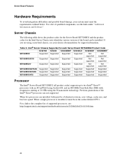
... Not supported Not supported SE7520BD2SATAD2 Supported Supported Supported Supported Supported Supported SE7520BD2SCSID2 Supported Supported Supported Supported Supported Supported SE7520BD2VD2 Supported Supported Supported Supported Supported Supported Processor The Intel® Server Board SE7520BD2 (all product codes) supports up to the complete list of the board can be installed...
... Not supported Not supported SE7520BD2SATAD2 Supported Supported Supported Supported Supported Supported SE7520BD2SCSID2 Supported Supported Supported Supported Supported Supported SE7520BD2VD2 Supported Supported Supported Supported Supported Supported Processor The Intel® Server Board SE7520BD2 (all product codes) supports up to the complete list of the board can be installed...
User Guide
Page 30
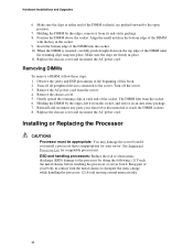
... off all peripheral devices connected to the open position. 7. Position the DIMM above the socket. Remove the chassis cover. 5. See Supported Processor List for your body in contact with the key in place. 11. Replace the chassis cover and reconnect the AC power cord. Reinstall and...DIMM by the edges, remove it in the bottom edge of electrostatic discharge (ESD) damage to dissipate the static charge while handling the processor. (2) Avoid moving around unnecessarily. 30 Gently spread the retaining clips at either end of the DIMM into place. Make sure the clips ...
... off all peripheral devices connected to the open position. 7. Position the DIMM above the socket. Remove the chassis cover. 5. See Supported Processor List for your body in contact with the key in place. 11. Replace the chassis cover and reconnect the AC power cord. Reinstall and...DIMM by the edges, remove it in the bottom edge of electrostatic discharge (ESD) damage to dissipate the static charge while handling the processor. (2) Avoid moving around unnecessarily. 30 Gently spread the retaining clips at either end of the DIMM into place. Make sure the clips ...

User Guide
Page 31
... raise the socket handle completely. TP00864 Figure 8. Turn off the server. 3. Observe the safety and ESD precautions at the beginning of the processor with the socket, and insert the processor into the socket. ✏ NOTE Make sure the alignment triangle mark and the alignment triangle cutout align correctly. Align the pins of...
... raise the socket handle completely. TP00864 Figure 8. Turn off the server. 3. Observe the safety and ESD precautions at the beginning of the processor with the socket, and insert the processor into the socket. ✏ NOTE Make sure the alignment triangle mark and the alignment triangle cutout align correctly. Align the pins of...
User Guide
Page 32
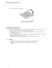
TP00865 Figure 9. Gradually and equally tighten each captive screw until all screws are tight. ✏ NOTE Boxed processor thermal solutions differ depending on the bottom of it. The heat sink has Thermal Interface Material (TIM) located on the chassis....Lever Installing the Heat Sink(s) 1. Set the heat sink over the processor, lining up the four captive screws with the four posts surrounding the processor. 3. Do not fully tighten one screw before tightening another. 4. See the boxed processor documentation for specifc instructions for the thermal solution. 32 Use caution when...
TP00865 Figure 9. Gradually and equally tighten each captive screw until all screws are tight. ✏ NOTE Boxed processor thermal solutions differ depending on the bottom of it. The heat sink has Thermal Interface Material (TIM) located on the chassis....Lever Installing the Heat Sink(s) 1. Set the heat sink over the processor, lining up the four captive screws with the four posts surrounding the processor. 3. Do not fully tighten one screw before tightening another. 4. See the boxed processor documentation for specifc instructions for the thermal solution. 32 Use caution when...
User Guide
Page 34
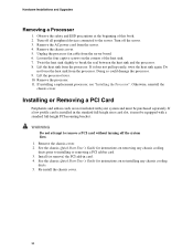
... any chassis cooling ducts prior to remove a PCI card without turning off the server. 3. Twist the heat sink slightly to the server. Lift the processor lever. 10. Remove the chassis cover. 2. Install (or remove) the PCI add-in cards are not included with a standard full-height PCI mounting...add-in card. 4. See the chassis Quick Start User's Guide for instructions on the corners of this book. 2. Unplug the processor fan cable from the processor. If it must be equipped with your system and must be purchased separately. Do not force the heat sink from the server board...
... any chassis cooling ducts prior to remove a PCI card without turning off the server. 3. Twist the heat sink slightly to the server. Lift the processor lever. 10. Remove the chassis cover. 2. Install (or remove) the PCI add-in cards are not included with a standard full-height PCI mounting...add-in card. 4. See the chassis Quick Start User's Guide for instructions on the corners of this book. 2. Unplug the processor fan cable from the processor. If it must be equipped with your system and must be purchased separately. Do not force the heat sink from the server board...
User Guide
Page 46
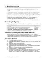
... Checklist ‰ Is AC power available at the AC source. ‰ Are all cables correctly connected and secured? ‰ Are the processors fully seated in their sockets on the server board? ‰ Are all standoffs in the proper location and not touching any components, causing ... correct? ‰ Are all peripherals. Hardware failure is with Newly Installed Application Software". Intel® Server Board SE7520BD2 User Guide 46 For any drivers used for a link to the software updates. Intel provides a package called the "Platform Confidence Test" that may help with your own, ...
... Checklist ‰ Is AC power available at the AC source. ‰ Are all cables correctly connected and secured? ‰ Are the processors fully seated in their sockets on the server board? ‰ Are all standoffs in the proper location and not touching any components, causing ... correct? ‰ Are all peripherals. Hardware failure is with Newly Installed Application Software". Intel® Server Board SE7520BD2 User Guide 46 For any drivers used for a link to the software updates. Intel provides a package called the "Platform Confidence Test" that may help with your own, ...
User Guide
Page 49
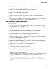
...make sure the Num Lock light is useful for your service representative or authorized dealer for changes to the system requirements. ‰ Carefully remove the processor(s) and re-seat them . ‰ Make sure the chassis standoffs are using an add-in video controller board, do not appear, the ...video display monitor or video controller may have been populated according to the system requirements. ‰ Remove the processor(s) and re-seat them . If successful, add the cards back in cards and see if the video returns. Misplaced standoffs can contact the ...
...make sure the Num Lock light is useful for your service representative or authorized dealer for changes to the system requirements. ‰ Carefully remove the processor(s) and re-seat them . ‰ Make sure the chassis standoffs are using an add-in video controller board, do not appear, the ...video display monitor or video controller may have been populated according to the system requirements. ‰ Remove the processor(s) and re-seat them . If successful, add the cards back in cards and see if the video returns. Misplaced standoffs can contact the ...
User Guide
Page 54
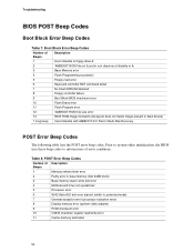
... image present in base memory (first 64KB block) 3 Base memory read / write test error 4 Motherboard timer not operational 5 Processor error 6 8042 Gate A20 test error (cannot switch to protected mode) 7 General exception error (processor exception error) 8 Display memory error (system video adapter) 9 ROM checksum error 10 CMOS shutdown register read/write error...
... image present in base memory (first 64KB block) 3 Base memory read / write test error 4 Motherboard timer not operational 5 Processor error 6 8042 Gate A20 test error (cannot switch to protected mode) 7 General exception error (processor exception error) 8 Display memory error (system video adapter) 9 ROM checksum error 10 CMOS shutdown register read/write error...


