
Product Guide
Page 3
Contents 1 Description...8 Server Board Features ...8 Server Board Connector and Component Locations 10 Back Panel Connectors 11 Intel® E7501 Chipset 12 Processor ...13 Memory ...15 PCI I/O Subsystem ...15 Video ...17 SCSI Controller...18 IDE Controller ...18 USB ...Management Controller 22 Field Replaceable Units and Sensor Data Records 22 System Event Log ...22 Platform Event Management 23 Emergency Management Port 23 Intel® Server Management 24 Security ...25 Summary of Software Security Features 25 Secure Mode ...27 Password Protection 28 Intrusion Switch Monitoring 29 ...
Contents 1 Description...8 Server Board Features ...8 Server Board Connector and Component Locations 10 Back Panel Connectors 11 Intel® E7501 Chipset 12 Processor ...13 Memory ...15 PCI I/O Subsystem ...15 Video ...17 SCSI Controller...18 IDE Controller ...18 USB ...Management Controller 22 Field Replaceable Units and Sensor Data Records 22 System Event Log ...22 Platform Event Management 23 Emergency Management Port 23 Intel® Server Management 24 Security ...25 Summary of Software Security Features 25 Secure Mode ...27 Password Protection 28 Intrusion Switch Monitoring 29 ...

Product Guide
Page 6
...the Top Assembly to the Server Board 54 Figure 10. Installing Processors 47 Figure 26. Applying Thermal Grease 48 6 Intel Server Board SE7501HG2 Product Guide Server Board Connector and Component Locations 10 Figure 2. Placing the Server Board in the Chassis 37 Figure 9. Applying Thermal Grease 40 ...132 Australia / New Zealand 132 9 Equipment Log Worksheet 133 Equipment Log ...133 Index ...135 Figures Figure 1. Routing the Floppy and Front Panel Cables 53 Figure 12. Opening Socket Lever and Attaching Processor 39 Figure 16. Attaching the Heat Sink Fan to the I /O Shield 33...
...the Top Assembly to the Server Board 54 Figure 10. Installing Processors 47 Figure 26. Applying Thermal Grease 48 6 Intel Server Board SE7501HG2 Product Guide Server Board Connector and Component Locations 10 Figure 2. Placing the Server Board in the Chassis 37 Figure 9. Applying Thermal Grease 40 ...132 Australia / New Zealand 132 9 Equipment Log Worksheet 133 Equipment Log ...133 Index ...135 Figures Figure 1. Routing the Floppy and Front Panel Cables 53 Figure 12. Opening Socket Lever and Attaching Processor 39 Figure 16. Attaching the Heat Sink Fan to the I /O Shield 33...

Product Guide
Page 9
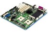
...; Two serial ports: One a-synch 9-pin RS-232C, one via 10-pin internal connector One Ethernet controller (Intel 82546EB) providing two 1-gigabit RJ45 connections Five USB ports: three stacked USB connectors in I/O rear panel, two via 10-pin internal header • SSI-EEB 3.0 compliant • Power/Sleep Switch with LED Indicator • Wake on...
...; Two serial ports: One a-synch 9-pin RS-232C, one via 10-pin internal connector One Ethernet controller (Intel 82546EB) providing two 1-gigabit RJ45 connections Five USB ports: three stacked USB connectors in I/O rear panel, two via 10-pin internal header • SSI-EEB 3.0 compliant • Power/Sleep Switch with LED Indicator • Wake on...

Product Guide
Page 13
... server board, are PS/2 compatible and are automatically detected and tested at 533 MHz. Parallel Port The SE7501HG2 baseboard provides a 25-pin parallel port back panel connector. Instead, they are interchangeable. Processor The Intel® Server Board SE7501HG2 accommodates one processor is installed, it should be in the socket labeled CPU1 and the other socket...
... server board, are PS/2 compatible and are automatically detected and tested at 533 MHz. Parallel Port The SE7501HG2 baseboard provides a 25-pin parallel port back panel connector. Instead, they are interchangeable. Processor The Intel® Server Board SE7501HG2 accommodates one processor is installed, it should be in the socket labeled CPU1 and the other socket...

Product Guide
Page 18
...functions. IDE Controller The system includes a dual-channel enhanced IDE 32-bit interface controller for both primary and secondary connectors on the front panel board. The device supports: • PIO, ATA-100 Synchronous DMA, and bus master IDE transfer modes •... on the system board, each of the USB Specification defines the external connectors. All five ports function identically and with the same bandwidth. 18 Intel Server Board SE7501HG2 Product Guide The Intel SE7501HG2 baseboard provides active terminators, termination voltage, resetable fuse, and protection diode ...
...functions. IDE Controller The system includes a dual-channel enhanced IDE 32-bit interface controller for both primary and secondary connectors on the front panel board. The device supports: • PIO, ATA-100 Synchronous DMA, and bus master IDE transfer modes •... on the system board, each of the USB Specification defines the external connectors. All five ports function identically and with the same bandwidth. 18 Intel Server Board SE7501HG2 Product Guide The Intel SE7501HG2 baseboard provides active terminators, termination voltage, resetable fuse, and protection diode ...

Product Guide
Page 54
Making Connections to the Server Board 54 Intel Server Board SE7501HG2 Product Guide Making Connections to the Server Board A B C 12 V D L E F G K J A I T H SCSI A 1 0 0 A Aux Power B Main Power C +12 V CPU Power D CPU1 Fan (top), CPU2 fan (bottom) E Floppy Disk Drive Connector F System Fan 5 (top), System Fan 4 (bottom) TP00030 G System Fan 3 H Front Panel Connector I Primary IDE (top), Secondary IDE (bottom) J SCSI Channel A (left), SCSI Channel B (right) K Chassis Intrusion L System Fan 1 (top), System Fan 2 (bottom) Figure 28.
Making Connections to the Server Board 54 Intel Server Board SE7501HG2 Product Guide Making Connections to the Server Board A B C 12 V D L E F G K J A I T H SCSI A 1 0 0 A Aux Power B Main Power C +12 V CPU Power D CPU1 Fan (top), CPU2 fan (bottom) E Floppy Disk Drive Connector F System Fan 5 (top), System Fan 4 (bottom) TP00030 G System Fan 3 H Front Panel Connector I Primary IDE (top), Secondary IDE (bottom) J SCSI Channel A (left), SCSI Channel B (right) K Chassis Intrusion L System Fan 1 (top), System Fan 2 (bottom) Figure 28.

Product Guide
Page 55
... Serial B serial port cable to either the front (rack configuration only) or back panels. See "Making Connections to their correspondingly numbered connector on your server baseboard. Installing the Serial B Cable For the Intel SC5200 chassis, you can be found on the system fan carrier and on the system... fan cables. Intel SC5200 Hot-Swap, Redundant Power Server Chassis Note Be sure to attach system fans to the Server Board" on the server board. Install the Serial B cable by inserting it into the chassis back panel cutout and attaching it to the Serial B connector located on the...
... Serial B serial port cable to either the front (rack configuration only) or back panels. See "Making Connections to their correspondingly numbered connector on your server baseboard. Installing the Serial B Cable For the Intel SC5200 chassis, you can be found on the system fan carrier and on the system... fan cables. Intel SC5200 Hot-Swap, Redundant Power Server Chassis Note Be sure to attach system fans to the Server Board" on the server board. Install the Serial B cable by inserting it into the chassis back panel cutout and attaching it to the Serial B connector located on the...

Product Guide
Page 116
... ! Is AC power available at the wall outlet, contact your service representative or authorized dealer for help . Is the cable from the front panel board connected to the server board? ! Are all relevant switches and jumpers on the diskette drive set to check the fan status)? ! If...". Are the fan power connectors properly connected to the system and the wall outlet? ! Are there any of the fan motors stopped (use the Setup Utility to make sure that "Onboard Floppy" is set to the server board SE7501HG2. 116 Intel Server Board SE7501HG2 Product Guide If the switches...
... ! Is AC power available at the wall outlet, contact your service representative or authorized dealer for help . Is the cable from the front panel board connected to the server board? ! Are all relevant switches and jumpers on the diskette drive set to check the fan status)? ! If...". Are the fan power connectors properly connected to the system and the wall outlet? ! Are there any of the fan motors stopped (use the Setup Utility to make sure that "Onboard Floppy" is set to the server board SE7501HG2. 116 Intel Server Board SE7501HG2 Product Guide If the switches...

Product Guide
Page 117
... Installation Tips" below . Are the CD-ROM drive's power and signal cables properly installed? ! Make sure the network cable is connected to the connector at the system back panel. Try the "PCI Installation Tips" below . ! Make sure the network cable is configured for more information on the drive set correctly? ! Make... sure you are using the drivers that are directly connecting two servers (no hub), you are visible through an opening at the system back panel. Check the network controller LEDs that are bound. ! Try reseating the add-in adapter was installed. !
... Installation Tips" below . Are the CD-ROM drive's power and signal cables properly installed? ! Make sure the network cable is connected to the connector at the system back panel. Try the "PCI Installation Tips" below . ! Make sure the network cable is configured for more information on the drive set correctly? ! Make... sure you are using the drivers that are directly connecting two servers (no hub), you are visible through an opening at the system back panel. Check the network controller LEDs that are bound. ! Try reseating the add-in adapter was installed. !

Product Guide
Page 135
...limiting access to SCU, 27 AIC-7902, 9, 13, 17 Alerting, 24 Alerts, 24 configuring, 24 APIC, 13 asset tag how to load, 104 Back panel connectors, 12 Baseboard Management Controller, 23, 81, 83 updating, 81 battery disposing of safely, 58 installing, 59 removing, 58 beep codes, 61 BIOS, 22, ...106 limiting access to system with administrative password, 27 reseting, 67 save and restore, 85, 106 configuring server board jumpers location on server board, 127 connector floppy disk, 14 keyboard, 14 mouse, 14 parallel port, 14 serial port, 14 USB, 10, 19 Console Redirection, 85 controller diskette, 69 ...
...limiting access to SCU, 27 AIC-7902, 9, 13, 17 Alerting, 24 Alerts, 24 configuring, 24 APIC, 13 asset tag how to load, 104 Back panel connectors, 12 Baseboard Management Controller, 23, 81, 83 updating, 81 battery disposing of safely, 58 installing, 59 removing, 58 beep codes, 61 BIOS, 22, ...106 limiting access to system with administrative password, 27 reseting, 67 save and restore, 85, 106 configuring server board jumpers location on server board, 127 connector floppy disk, 14 keyboard, 14 mouse, 14 parallel port, 14 serial port, 14 USB, 10, 19 Console Redirection, 85 controller diskette, 69 ...
Product Guide
Page 136
...configuring, 73 Events, 24 alerts, 24 fan heat sink, disconnecting, 51 Fast Ethernet, 10 FC-mPGA2, 9 feature summary back panel connectors, 12 Field Replaceable Unit, 23, 81, 83, 84, 85 viewing, 90 firmware update, 91 Firmware Update Utility, 81, 100...to run, 100 fixed disk write protect, 30 Fliphip-micro Pin Grid Array2, 9 Floppy A select type, 65 floppy disk connector, 14 floppy disk controller, 14 floppy write-protect, 10 form factor, 10 FRU, 23 FRU/SDR Load Utility, 23,... 79 Hot keys, 28 I/O PCI expansion slots, 9 ports provided, 10 I/O shield, 33, 45 Intel Server Board SE7501HG2 Product Guide
...configuring, 73 Events, 24 alerts, 24 fan heat sink, disconnecting, 51 Fast Ethernet, 10 FC-mPGA2, 9 feature summary back panel connectors, 12 Field Replaceable Unit, 23, 81, 83, 84, 85 viewing, 90 firmware update, 91 Firmware Update Utility, 81, 100...to run, 100 fixed disk write protect, 30 Fliphip-micro Pin Grid Array2, 9 Floppy A select type, 65 floppy disk connector, 14 floppy disk controller, 14 floppy write-protect, 10 form factor, 10 FRU, 23 FRU/SDR Load Utility, 23,... 79 Hot keys, 28 I/O PCI expansion slots, 9 ports provided, 10 I/O shield, 33, 45 Intel Server Board SE7501HG2 Product Guide


