
User Guide
Page 3
... specific BIOS settings and screens is compatible with your server: Processor, memory DIMMs, hard drive, floppy drive, CD-ROM or DVD-ROM drive, RAID controller, operating system. This document provides a brief overview of the features of the board/chassis, a list of accessories or other components. This manual is written for system technicians who are shipped with the board or that may be used with the following accessory items for performing troubleshooting activities to reset the password...
... specific BIOS settings and screens is compatible with your server: Processor, memory DIMMs, hard drive, floppy drive, CD-ROM or DVD-ROM drive, RAID controller, operating system. This document provides a brief overview of the features of the board/chassis, a list of accessories or other components. This manual is written for system technicians who are shipped with the board or that may be used with the following accessory items for performing troubleshooting activities to reset the password...

User Guide
Page 4
... and Operating System List" Search for "Reference Chassis List" Search for "Supported Processors" Search for "Supported Memory" Search for "Power Budget" Search for "Intel Server Management" Search for "Driver" (for an extensive list of drivers available) Search for "Operating System Driver" (for operating system drivers) For firmware and BIOS updates Search for "Firmware Update" For diagnostics test software Search for "Technical Product Specification" See the Intel® Server Board SE7320VP2 Quick Start User's Guide in the...
... and Operating System List" Search for "Reference Chassis List" Search for "Supported Processors" Search for "Supported Memory" Search for "Power Budget" Search for "Intel Server Management" Search for "Driver" (for an extensive list of drivers available) Search for "Operating System Driver" (for operating system drivers) For firmware and BIOS updates Search for "Firmware Update" For diagnostics test software Search for "Technical Product Specification" See the Intel® Server Board SE7320VP2 Quick Start User's Guide in the...

User Guide
Page 7
...power button. 3. Label and disconnect all caution and safety statements in this document before performing any unpainted metal surface- A microprocessor and heat sink may be sharp pins and edges on the Resource CD and/or at http://support.intel.com/support/motherboards/server/. Arbeiten an Platinen und Gehäuse...hot if the system has been running. Turn off all AC power cords from the system or from wall outlets. 4. Provide some board and chassis parts. Preface Safety Cautions Read all cables connected to I /O Anschlüssen oder Ports ab. 5. Außerdem kö...
...power button. 3. Label and disconnect all caution and safety statements in this document before performing any unpainted metal surface- A microprocessor and heat sink may be sharp pins and edges on the Resource CD and/or at http://support.intel.com/support/motherboards/server/. Arbeiten an Platinen und Gehäuse...hot if the system has been running. Turn off all AC power cords from the system or from wall outlets. 4. Provide some board and chassis parts. Preface Safety Cautions Read all cables connected to I /O Anschlüssen oder Ports ab. 5. Außerdem kö...
User Guide
Page 11
... 25 Installing and Removing Memory 25 Installing DIMMs...25 Removing DIMMs...27 Installing or Replacing the Processor 28 Installing the Processor 28 Removing a Processor 30 RJ45 Serial Port Configuration 31 Installing a PCI, PCI-X, or PCI-Express* Add-in Card 32 Replacing the Backup Battery 32 3 Server Utilities 34 Using the BIOS Setup Utility 34 Starting Setup ...34 If You Cannot Access Setup 34 Setup Menus ...34 Upgrading the BIOS ...36 Preparing for the Upgrade 36 Upgrading the BIOS ...37 Clearing the Password ...37 Clearing the CMOS ...38 4 Troubleshooting 39 Resetting the...
... 25 Installing and Removing Memory 25 Installing DIMMs...25 Removing DIMMs...27 Installing or Replacing the Processor 28 Installing the Processor 28 Removing a Processor 30 RJ45 Serial Port Configuration 31 Installing a PCI, PCI-X, or PCI-Express* Add-in Card 32 Replacing the Backup Battery 32 3 Server Utilities 34 Using the BIOS Setup Utility 34 Starting Setup ...34 If You Cannot Access Setup 34 Setup Menus ...34 Upgrading the BIOS ...36 Preparing for the Upgrade 36 Upgrading the BIOS ...37 Clearing the Password ...37 Clearing the CMOS ...38 4 Troubleshooting 39 Resetting the...

User Guide
Page 12
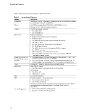
... Diskette Drive Activity Light Does Not Light 44 CD-ROM Drive or DVD-ROM Drive Activity Light Does Not Light 45 Cannot Connect to a Server 45 Problems with Network 45 System Boots when Installing PCI Card 46 Problems with Newly Installed Application Software 46 Problems with Application Software that Ran Correctly Earlier 46 Devices are not Recognized under Device Manager (Windows* Operating System).. 47 Hard Drive(s) are not Recognized 47 Bootable CD-ROM Is Not Detected 47 LED Information...
... Diskette Drive Activity Light Does Not Light 44 CD-ROM Drive or DVD-ROM Drive Activity Light Does Not Light 45 Cannot Connect to a Server 45 Problems with Network 45 System Boots when Installing PCI Card 46 Problems with Newly Installed Application Software 46 Problems with Application Software that Ran Correctly Earlier 46 Devices are not Recognized under Device Manager (Windows* Operating System).. 47 Hard Drive(s) are not Recognized 47 Bootable CD-ROM Is Not Detected 47 LED Information...
User Guide
Page 16
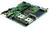
...; processors with PCI, PCI-X, and/or PCI-Express* slots. Video On-board ATI* RAGE XL video controller with 8MB SDRAM Hard Drive Ultra ATA/100 support: ƒ Two IDE channels that is capable of the server board. This connector supports a riser card with an 800 MT/s MHz front side bus and frequencies starting at 2.8 GHz. Server Board Features Table 1 summarizes the major features of speeds up to 66 MHz. ƒ One full-height riser connector, utilizing Intel...
...; processors with PCI, PCI-X, and/or PCI-Express* slots. Video On-board ATI* RAGE XL video controller with 8MB SDRAM Hard Drive Ultra ATA/100 support: ƒ Two IDE channels that is capable of the server board. This connector supports a riser card with an 800 MT/s MHz front side bus and frequencies starting at 2.8 GHz. Server Board Features Table 1 summarizes the major features of speeds up to 66 MHz. ƒ One full-height riser connector, utilizing Intel...

User Guide
Page 17
... U Configuration jumpers B Battery L +12V processor power connector V SATA 1 connector C Full-height PCI slot M Fan board connector W SATA 0 connector D Low-profile PCI slot N Floppy connector Z Power supply connector E Back panel I/O ports O PCI fan connecors (two) Y OEM RMC connector F Serial port selection jumper P IDE connector Z Front panel USB header G DIMM sockets Q 100-pin Floppy / Front Panel / AA IDE power connector ATA connector H Processor 1 fan header R Main power connector BB BIOS Select jumper I Processor 1 socket S 50-pin front panel connector CC Chassis...
... U Configuration jumpers B Battery L +12V processor power connector V SATA 1 connector C Full-height PCI slot M Fan board connector W SATA 0 connector D Low-profile PCI slot N Floppy connector Z Power supply connector E Back panel I/O ports O PCI fan connecors (two) Y OEM RMC connector F Serial port selection jumper P IDE connector Z Front panel USB header G DIMM sockets Q 100-pin Floppy / Front Panel / AA IDE power connector ATA connector H Processor 1 fan header R Main power connector BB BIOS Select jumper I Processor 1 socket S 50-pin front panel connector CC Chassis...

User Guide
Page 23
... same time. Memory Sparing and Mirroring The Intel® E7320 chipset supports memory mirroring and memory on the server board, but when mixing DIMM types, DDR333 memory will not fail due to prevent data loss in the memory subsystem. The system will be treated as DDR266. ƒ Use only DIMMs with DIMM organization of four DIMMs installed. For a complete list of the data...
... same time. Memory Sparing and Mirroring The Intel® E7320 chipset supports memory mirroring and memory on the server board, but when mixing DIMM types, DDR333 memory will not fail due to prevent data loss in the memory subsystem. The system will be treated as DDR266. ƒ Use only DIMMs with DIMM organization of four DIMMs installed. For a complete list of the data...

User Guide
Page 24
... channel is used as the memory spare. For a link to the Intel® Server Board SE7320VP2 Technical Product Specification for additional drive information and drive installation instructions. 24 For direct-plug IDE flash drives, use , but is available through the standard floppy connector or through the 100pin front panel connector if you have installed the optional hot-swap backplane. Optional Hardware Storage Devices The Server Board SE7320VP2 provides two SATA connections and two ATA (IDE/ATAPI) controllers. Each ATA connection supports...
... channel is used as the memory spare. For a link to the Intel® Server Board SE7320VP2 Technical Product Specification for additional drive information and drive installation instructions. 24 For direct-plug IDE flash drives, use , but is available through the standard floppy connector or through the 100pin front panel connector if you have installed the optional hot-swap backplane. Optional Hardware Storage Devices The Server Board SE7320VP2 provides two SATA connections and two ATA (IDE/ATAPI) controllers. Each ATA connection supports...

User Guide
Page 25
... "Memory" for a discussion of the board. Turn off all peripheral devices connected to the processor socket. Intel® Server Board SE7320VP2 User Guide 25 See "Additional Information and Software" for the DIMMs displays DIMM1B, DIMM1A, DIMM2B, DIMM2A, DIMM3B, and DIMM3A, starting from the server. 2 Hardware Installations and Upgrades Before You Begin Before working with your server product, pay close attention to the list of tested DIMMs. Installing DIMMs To install...
... "Memory" for a discussion of the board. Turn off all peripheral devices connected to the processor socket. Intel® Server Board SE7320VP2 User Guide 25 See "Additional Information and Software" for the DIMMs displays DIMM1B, DIMM1A, DIMM2B, DIMM2A, DIMM3B, and DIMM3A, starting from the server. 2 Hardware Installations and Upgrades Before You Begin Before working with your server product, pay close attention to the list of tested DIMMs. Installing DIMMs To install...

User Guide
Page 31
... damage the processor. 9. Otherwise, reinstall the chassis cover. To change the configuration to cover pins 2 and 4. Move the jumper from the server. 4. If installing a replacement processor, see "Installing the Processor." RJ45 Serial Port Configuration The RJ45 serial port connector can be changed. Disconnect the AC power cord from the default position covering pins 1 and 3 to support DCD signals a jumper on removing the server's cover. 5. If it is configured to support DCD signals. 1. Turn off all peripheral devices connected to...
... damage the processor. 9. Otherwise, reinstall the chassis cover. To change the configuration to cover pins 2 and 4. Move the jumper from the server. 4. If installing a replacement processor, see "Installing the Processor." RJ45 Serial Port Configuration The RJ45 serial port connector can be changed. Disconnect the AC power cord from the default position covering pins 1 and 3 to support DCD signals a jumper on removing the server's cover. 5. If it is configured to support DCD signals. 1. Turn off all peripheral devices connected to...

User Guide
Page 39
.... Clear system memory, restart POST, and reload the operating system. 4 Troubleshooting This chapter helps you identify and solve problems that may help with your diagnostics. See "Additional Information and Software" for assistance. Turn the system power off /on Intel® Server Board SE7320VP2 User Guide 39 In addition to the server firmware and files, also update any issue, first ensure you are unable to perform reset...
.... Clear system memory, restart POST, and reload the operating system. 4 Troubleshooting This chapter helps you identify and solve problems that may help with your diagnostics. See "Additional Information and Software" for assistance. Turn the system power off /on Intel® Server Board SE7320VP2 User Guide 39 In addition to the server firmware and files, also update any issue, first ensure you are unable to perform reset...

User Guide
Page 40
... devices installed correctly? ‰ If the system has a hard disk drive, is with a specific software application, see "Problems with them. Refer to the manufacturer's documentation that there are experiencing is it properly formatted or configured? ‰ Are all device drivers properly installed? ‰ Are the configuration settings made in ? First Steps Checklist ‰ Is AC power available at the wall outlet? ‰ Are the power supplies plugged in Setup...
... devices installed correctly? ‰ If the system has a hard disk drive, is with a specific software application, see "Problems with them. Refer to the manufacturer's documentation that there are experiencing is it properly formatted or configured? ‰ Are all device drivers properly installed? ‰ Are the configuration settings made in ? First Steps Checklist ‰ Is AC power available at the wall outlet? ‰ Are the power supplies plugged in Setup...

User Guide
Page 42
...; Some ATX power supplies have a power switch on the back of the server board and cause a short. 42 If your service representative or authorized dealer for these specific problems: ƒ Power light does not light. ƒ No characters appear on screen. ƒ Characters on the bottom of the power supply, next to the server board might be defective or the cable from the front panel to the fan. Misplaced standoffs...
...; Some ATX power supplies have a power switch on the back of the server board and cause a short. 42 If your service representative or authorized dealer for these specific problems: ƒ Power light does not light. ƒ No characters appear on screen. ƒ Characters on the bottom of the power supply, next to the server board might be defective or the cable from the front panel to the fan. Misplaced standoffs...

User Guide
Page 43
... video monitor? See the manufacturer's documentation. ‰ Are the video monitor's signal and power cables properly installed? ‰ Does this video monitor work correctly if plugged into a different system? ‰ Is the onboard video controller enabled in the BIOS? ‰ Remove all add-in and turned on the screen after you reboot the system and POST emits a beep code, write down the beep code you are still no characters on ? If there are using the onboard video controller...
... video monitor? See the manufacturer's documentation. ‰ Are the video monitor's signal and power cables properly installed? ‰ Does this video monitor work correctly if plugged into a different system? ‰ Is the onboard video controller enabled in the BIOS? ‰ Remove all add-in and turned on the screen after you reboot the system and POST emits a beep code, write down the beep code you are still no characters on ? If there are using the onboard video controller...

User Guide
Page 44
... "Enabled." If not, see "Power Light Does Not Light" ‰ If your fans speeded up in incorrectly. If you are using the onboard diskette controller, use the BIOS setup to make sure that "Onboard Floppy" is set to an overheating situation? ‰ Have your system has LED lights for the fans, is one or more of these LEDs lit? ‰ Are any other front panel LEDs lit? ‰ Have any shorted wires caused...
... "Enabled." If not, see "Power Light Does Not Light" ‰ If your fans speeded up in incorrectly. If you are using the onboard diskette controller, use the BIOS setup to make sure that "Onboard Floppy" is set to an overheating situation? ‰ Have your system has LED lights for the fans, is one or more of these LEDs lit? ‰ Are any other front panel LEDs lit? ‰ Have any shorted wires caused...

User Guide
Page 45
... PCI drivers. The controller stopped working when an add-in adapter. 45 See "Additional Information and Software" for the same duplex mode as the network controller. ‰ Make sure the correct networking software is securely attached. ‰ Make sure you are bound. ‰ Make sure the hub port is configured for a link to a Server ‰ Make sure the network cable is current. Troubleshooting CD-ROM Drive or DVD-ROM Drive...
... PCI drivers. The controller stopped working when an add-in adapter. 45 See "Additional Information and Software" for the same duplex mode as the network controller. ‰ Make sure the correct networking software is securely attached. ‰ Make sure you are bound. ‰ Make sure the hub port is configured for a link to a Server ‰ Make sure the network cable is current. Troubleshooting CD-ROM Drive or DVD-ROM Drive...

User Guide
Page 46
... component failures. 46 Make sure all necessary files are installed. ‰ If the problems are running the software from a diskette, CD-ROM or DVD-ROM, try a different diskette. ‰ Check your system for a virus infection. ‰ Uninstall and reinstall the software. System Boots when Installing PCI Card System Server Management features require full-time "standby" power. Before installing a PCI card, you are intermittent, there may be a loose cable...
... component failures. 46 Make sure all necessary files are installed. ‰ If the problems are running the software from a diskette, CD-ROM or DVD-ROM, try a different diskette. ‰ Check your system for a virus infection. ‰ Uninstall and reinstall the software. System Boots when Installing PCI Card System Server Management features require full-time "standby" power. Before installing a PCI card, you are intermittent, there may be a loose cable...
User Guide
Page 47
... drives. ‰ If using a RAID configuration with SCSI or SATA drives, make sure the RAID card is uniqe on the power line, you may be the first bootable device. 47 See "Additional Information and Software" for a link to the current drivers and chipset files. Hard Drive(s) are not Recognized Check the following : ‰ Make sure the BIOS is compatible. See your power line. Symptoms of the drivers for the Intel® chipsets, onboard...
... drives. ‰ If using a RAID configuration with SCSI or SATA drives, make sure the RAID card is uniqe on the power line, you may be the first bootable device. 47 See "Additional Information and Software" for a link to the current drivers and chipset files. Hard Drive(s) are not Recognized Check the following : ‰ Make sure the BIOS is compatible. See your power line. Symptoms of the drivers for the Intel® chipsets, onboard...

User Guide
Page 48
... board rear left corner ATA drive activity Memory fault 1-6 POST code 1-4 (LSB, bit1, bit2, MSB) Control panel Identify failing memory module Display boot 80 POST code Control panel and board left board Control Panel Color Blue Green or Amber Green Amber Correction Press ID LED button or user Server Management software to turn off or S5) On = Power on or S0) Slow Blink = Low power state (S1 - On = No Fault Green Blink = degraded Amber = critical error...
... board rear left corner ATA drive activity Memory fault 1-6 POST code 1-4 (LSB, bit1, bit2, MSB) Control panel Identify failing memory module Display boot 80 POST code Control panel and board left board Control Panel Color Blue Green or Amber Green Amber Correction Press ID LED button or user Server Management software to turn off or S5) On = Power on or S0) Slow Blink = Low power state (S1 - On = No Fault Green Blink = degraded Amber = critical error...


