
Product Specification
Page 6
...Contents Intel® Entry Server Board SE7221BA1-E TPS 7.3 BIOS Flash Memory Organization 40 7.4 Resource Configuration 40 7.4.1 PCI Autoconfiguration 40 7.4.2 PCI IDE Support ...40 7.5 System Management BIOS (SMBIOS 41 7.6 Legacy USB Support 41 7.7 BIOS Updates...42 7.7.1 Language Support 42 7.7.2 Custom Splash Screen 42 7.8 Boot Options ...42 7.8.1 CD-ROM Boot...42 7.8.2 Network Boot ...42 7.8.3 Booting Without Attached Devices 42 7.9 BIOS Security Features 43 7.10 Error Messages and Beep Codes 44 7.10.1 BIOS Error Messages 44 7.10.2 Port 80h POST Codes...
...Contents Intel® Entry Server Board SE7221BA1-E TPS 7.3 BIOS Flash Memory Organization 40 7.4 Resource Configuration 40 7.4.1 PCI Autoconfiguration 40 7.4.2 PCI IDE Support ...40 7.5 System Management BIOS (SMBIOS 41 7.6 Legacy USB Support 41 7.7 BIOS Updates...42 7.7.1 Language Support 42 7.7.2 Custom Splash Screen 42 7.8 Boot Options ...42 7.8.1 CD-ROM Boot...42 7.8.2 Network Boot ...42 7.8.3 Booting Without Attached Devices 42 7.9 BIOS Security Features 43 7.10 Error Messages and Beep Codes 44 7.10.1 BIOS Error Messages 44 7.10.2 Port 80h POST Codes...
Product Specification
Page 9
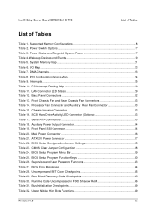
... Shadow RAM 46 Table 31. Intel® Entry Server Board SE7221BA1-E TPS List of Tables List of Tables Table 1. Supported Memory Configurations 8 Table 2. DMA Channels...23 Table 8. PCI Interrupt Routing Map 26 Table 11. Main Power Connector 36 Table 21. BIOS Setup Configuration Jumper Settings 38 Table 23. Boot Block Recovery Code Checkpoints 45 Table 30. Wake-up Devices and Events 19 Table 5. Interrupts...25 Table 10. LAN Connector LED States 29 Table 12. Processor Fan Connector and Auxiliary Rear Fan Connector...
... Shadow RAM 46 Table 31. Intel® Entry Server Board SE7221BA1-E TPS List of Tables List of Tables Table 1. Supported Memory Configurations 8 Table 2. DMA Channels...23 Table 8. PCI Interrupt Routing Map 26 Table 11. Main Power Connector 36 Table 21. BIOS Setup Configuration Jumper Settings 38 Table 23. Boot Block Recovery Code Checkpoints 45 Table 30. Wake-up Devices and Events 19 Table 5. Interrupts...25 Table 10. LAN Connector LED States 29 Table 12. Processor Fan Connector and Auxiliary Rear Fan Connector...
Product Specification
Page 16
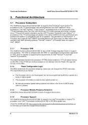
... Board SE7221BA1-E supports Intel® Pentium® 4 and Celeron® D processors in an LGA775 processor socket with enhancements to as follows: • The Processor will not turn on the VRD. 3.1.2 Reset Configuration Logic The BIOS determines the processor stepping, cache size, etc through the CPUID instruction. Check the Intel® web site http://support.intel.com/support/motherboards/server/se7221ba1-e/ for the most up-to-date list of the Pentium® 4 Processor also supports Intel...
... Board SE7221BA1-E supports Intel® Pentium® 4 and Celeron® D processors in an LGA775 processor socket with enhancements to as follows: • The Processor will not turn on the VRD. 3.1.2 Reset Configuration Logic The BIOS determines the processor stepping, cache size, etc through the CPUID instruction. Check the Intel® web site http://support.intel.com/support/motherboards/server/se7221ba1-e/ for the most up-to-date list of the Pentium® 4 Processor also supports Intel...
Product Specification
Page 17
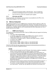
... processors listed on the front side bus. 3.2 Memory Subsystem The baseboard supports up -to the processor is x72, which slot the memory error has occured. If the module is fully seated and both latches are not supported. • 4 GB maximum total system memory. The memory controller supports memory scrubbing, single-bit error correction and multiple-bit error detection. The MCH can damage the board, the processor, and the power supply. 2. Intel® Entry Server Board SE7221BA1...
... processors listed on the front side bus. 3.2 Memory Subsystem The baseboard supports up -to the processor is x72, which slot the memory error has occured. If the module is fully seated and both latches are not supported. • 4 GB maximum total system memory. The memory controller supports memory scrubbing, single-bit error correction and multiple-bit error detection. The MCH can damage the board, the processor, and the power supply. 2. Intel® Entry Server Board SE7221BA1...

Product Specification
Page 18
...-sided memory modules (containing one channel to the other but the installed memory capacity for each channel must be used. Technology and device width can vary from one row of SDRAM). 3.2.2 Memory Configurations The Intel® E7221MC GMCH supports two types of memory organization: • Dual channel (Interleaved) mode. The DIMM1 sockets of both channels are black. 8 Revision 1.5 Supported DIMM Configurations Table 1. NOTE The DIMM0 sockets of both channels are blue. This mode offers...
...-sided memory modules (containing one channel to the other but the installed memory capacity for each channel must be used. Technology and device width can vary from one row of SDRAM). 3.2.2 Memory Configurations The Intel® E7221MC GMCH supports two types of memory organization: • Dual channel (Interleaved) mode. The DIMM1 sockets of both channels are black. 8 Revision 1.5 Supported DIMM Configurations Table 1. NOTE The DIMM0 sockets of both channels are blue. This mode offers...

Product Specification
Page 22
... PCI Express* Graphics bus, and the DMI interconnect. The BIOS supports Logical Block Addressing (LBA) and Extended Cylinder Head Sector (ECHS) translation modes. ATA-66 protocol is similar to Ultra DMA and is as CD-ROM drives) and ATA devices using the transfer modes. The ICH6-R is a centralized controller for all ports. The FWH provides the nonvolatile storage of the BIOS. 3.3.1 USB Interface The Intel® Entry Server Board SE7221BA1-E supports...
... PCI Express* Graphics bus, and the DMI interconnect. The BIOS supports Logical Block Addressing (LBA) and Extended Cylinder Head Sector (ECHS) translation modes. ATA-66 protocol is similar to Ultra DMA and is as CD-ROM drives) and ATA devices using the transfer modes. The ICH6-R is a centralized controller for all ports. The FWH provides the nonvolatile storage of the BIOS. 3.3.1 USB Interface The Intel® Entry Server Board SE7221BA1-E supports...

Product Specification
Page 23
... add-in hard drive controller or the onboard IDE controller (Parallel ATA or Serial ATA). 3.3.3 Real-Time Clock, CMOS SRAM, and Battery A coin-cell battery (CR2032) powers the real-time clock and CMOS memory. Native mode is written or retrieved from , or written to device connections, unlike Parallel ATA IDE which supports a master/slave configuration and two devices per port. Create a RAID array. 3. Format the RAID array. 3.3.2.5 SCSI Hard Drive Activity LED Connector (Optional) The SCSI hard drive activity LED connector is used for a maximum...
... add-in hard drive controller or the onboard IDE controller (Parallel ATA or Serial ATA). 3.3.3 Real-Time Clock, CMOS SRAM, and Battery A coin-cell battery (CR2032) powers the real-time clock and CMOS memory. Native mode is written or retrieved from , or written to device connections, unlike Parallel ATA IDE which supports a master/slave configuration and two devices per port. Create a RAID array. 3. Format the RAID array. 3.3.2.5 SCSI Hard Drive Activity LED Connector (Optional) The SCSI hard drive activity LED connector is used for a maximum...

Product Specification
Page 24
...• PCI Conventional bus power management support The BIOS Setup program provides configuration options for the I/O controller. 3.4.1 Serial Port The Intel® Entry Server Board SE7221BA1-E has one serial port connector located on the back panel, and a serial port B header on the board. Use the BIOS Setup program to set the parallel port mode. 3.4.3 Diskette Drive Controller The I /O controller provides the following : • Fan monitoring and control (through the hardware monitoring and fan control ASIC) • Thermal and voltage monitoring • Chassis intrusion detection...
...• PCI Conventional bus power management support The BIOS Setup program provides configuration options for the I/O controller. 3.4.1 Serial Port The Intel® Entry Server Board SE7221BA1-E has one serial port connector located on the back panel, and a serial port B header on the board. Use the BIOS Setup program to set the parallel port mode. 3.4.3 Diskette Drive Controller The I /O controller provides the following : • Fan monitoring and control (through the hardware monitoring and fan control ASIC) • Thermal and voltage monitoring • Chassis intrusion detection...

Product Specification
Page 28
... the fan speed or switch the fan on or off the system power through system control. Functional Architecture Intel® Entry Server Board SE7221BA1-E TPS 1. When resuming from an AC power failure, the server returns to a fan tachometer input of the hardware monitoring and fan control ASIC • All fan connectors support closed-loop fan control that provides full ACPI support. 3.6.3.1 Power Connector ATX12V-compliant power supplies can be set using the Last Power State feature in the BIOS Setup program's Boot menu. 3.6.3.2 Fan Connectors...
... the fan speed or switch the fan on or off the system power through system control. Functional Architecture Intel® Entry Server Board SE7221BA1-E TPS 1. When resuming from an AC power failure, the server returns to a fan tachometer input of the hardware monitoring and fan control ASIC • All fan connectors support closed-loop fan control that provides full ACPI support. 3.6.3.1 Power Connector ATX12V-compliant power supplies can be set using the Last Power State feature in the BIOS Setup program's Boot menu. 3.6.3.2 Fan Connectors...
Product Specification
Page 31
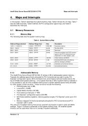
... MB) • PCI Express* configuration space (256 MB) • MCH base address registers, internal graphics ranges, PCI Express* ports (up to the PCI Conventional bus). Dependent on add-in cards and BIOS settings. On a system that has 4 GB of system memory installed, it is dynamically allocated for PCI Conventional bus add-in cards The amount of installed memory that is not possible to use all of DRAM (total system memory). Maps and Interrupts...
... MB) • PCI Express* configuration space (256 MB) • MCH base address registers, internal graphics ranges, PCI Express* ports (up to the PCI Conventional bus). Dependent on add-in cards and BIOS settings. On a system that has 4 GB of system memory installed, it is dynamically allocated for PCI Conventional bus add-in cards The amount of installed memory that is not possible to use all of DRAM (total system memory). Maps and Interrupts...

Product Specification
Page 48
... booting. After the POST runs, Setup runs automatically. The BIOS attempts to default values. The maintenance menu is required. Normal operation, BIOS uses current configuration information. 38 Revision 1.5 Function/Mode Normal Clear CMOS No Jumper Table 23. Location of the Jumper Block OM16682 Table 22. During POST, the CMOS configuration is reset to recover the BIOS configuration. Connections and Jumper Blocks Intel® Entry Server Board SE7221BA1-E TPS 1 3 J6J3 Figure 16. A recovery diskette is displayed. CMOS Clear Jumper Configuration Jumper Setting...
... booting. After the POST runs, Setup runs automatically. The BIOS attempts to default values. The maintenance menu is required. Normal operation, BIOS uses current configuration information. 38 Revision 1.5 Function/Mode Normal Clear CMOS No Jumper Table 23. Location of the Jumper Block OM16682 Table 22. During POST, the CMOS configuration is reset to recover the BIOS configuration. Connections and Jumper Blocks Intel® Entry Server Board SE7221BA1-E TPS 1 3 J6J3 Figure 16. A recovery diskette is displayed. CMOS Clear Jumper Configuration Jumper Setting...

Product Specification
Page 49
... BIOS Setup program, POST, the PCI auto-configuration utility, and Plug and Play support. The BIOS Setup program can be used to Table 22 for the computer. The BIOS displays a message during POST identifying the type of BIOS and a revision code. The BIOS Setup program is shown below. The menu bar is accessed by pressing the key after the Power-On Self-Test (POST) memory test begins and before the operating system boot begins. Intel® Entry Server Board SE7221BA1...
... BIOS Setup program, POST, the PCI auto-configuration utility, and Plug and Play support. The BIOS Setup program can be used to Table 22 for the computer. The BIOS displays a message during POST identifying the type of BIOS and a revision code. The BIOS Setup program is shown below. The menu bar is accessed by pressing the key after the Power-On Self-Test (POST) memory test begins and before the operating system boot begins. Intel® Entry Server Board SE7221BA1...
Product Specification
Page 50
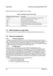
... exits the BIOS Setup program Exits the menu 7.3 BIOS Flash Memory Organization The Firmware Hub (FWH) includes an 8 Mbit (1024 KB) symmetrical flash memory device. 7.4 Resource Configuration 7.4.1 PCI Autoconfiguration The BIOS can override the auto-configuration options by the add-in card. 7.4.2 PCI IDE Support If you select Auto in the BIOS Setup program, the BIOS automatically sets up or down) Selects a field (Not implemented) Executes command or selects the submenu Load the default configuration values for use ATA...
... exits the BIOS Setup program Exits the menu 7.3 BIOS Flash Memory Organization The Firmware Hub (FWH) includes an 8 Mbit (1024 KB) symmetrical flash memory device. 7.4 Resource Configuration 7.4.1 PCI Autoconfiguration The BIOS can override the auto-configuration options by the add-in card. 7.4.2 PCI IDE Support If you select Auto in the BIOS Setup program, the BIOS automatically sets up or down) Selects a field (Not implemented) Executes command or selects the submenu Load the default configuration values for use ATA...
Product Specification
Page 51
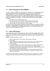
... used to configure the operating system. (Keyboards and mice are not yet available. To install an operating system that supports USB, verify that supports USB. Intel® Entry Server Board SE7221BA1-E TPS System BIOS 7.5 System Management BIOS (SMBIOS) The main component of SMBIOS is set to Enabled and follow the operating system's installation instructions. The BIOS enables applications such as follows: 1. POST completes. 5. After the operating system loads the USB drivers, all legacy and non-legacy USB devices...
... used to configure the operating system. (Keyboards and mice are not yet available. To install an operating system that supports USB, verify that supports USB. Intel® Entry Server Board SE7221BA1-E TPS System BIOS 7.5 System Management BIOS (SMBIOS) The main component of SMBIOS is set to Enabled and follow the operating system's installation instructions. The BIOS enables applications such as follows: 1. POST completes. 5. After the operating system loads the USB drivers, all legacy and non-legacy USB devices...
Product Specification
Page 52
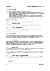
... disabled. 7.8.1 CD-ROM Boot Booting from CD-ROM is invoked even if the following utilities: • Intel® Express BIOS Update utility, which requires creation of a boot diskette and manual rebooting of the following devices are supported in priority order. Pressing the key during POST, the User Access Level in the BIOS Setup program's Security menu must be updated from a file on a hard disk, a 1.44 MB diskette, or a CD-ROM. • Intel® Flash Memory Update Utility, which enables automated updating while in the BIOS Setup...
... disabled. 7.8.1 CD-ROM Boot Booting from CD-ROM is invoked even if the following utilities: • Intel® Express BIOS Update utility, which requires creation of a boot diskette and manual rebooting of the following devices are supported in priority order. Pressing the key during POST, the User Access Level in the BIOS Setup program's Security menu must be updated from a file on a hard disk, a 1.44 MB diskette, or a CD-ROM. • Intel® Flash Memory Update Utility, which enables automated updating while in the BIOS Setup...
Product Specification
Page 53
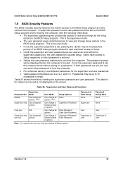
... supervisor password is set , users can enter either password to boot the computer. • For enhanced security, use different passwords for a password. Table 26. This is set, the computer boots without asking for the supervisor and user passwords. • Valid password characters are set , any user can change Setup options in the BIOS Setup program. Intel® Entry Server Board SE7221BA1-E TPS System BIOS 7.9 BIOS Security Features The BIOS includes security features that restrict access to the BIOS Setup program...
... supervisor password is set , users can enter either password to boot the computer. • For enhanced security, use different passwords for a password. Table 26. This is set, the computer boots without asking for the supervisor and user passwords. • Valid password characters are set , any user can change Setup options in the BIOS Setup program. Intel® Entry Server Board SE7221BA1-E TPS System BIOS 7.9 BIOS Security Features The BIOS includes security features that restrict access to the BIOS Setup program...

Product Specification
Page 54
... testing L2 cache. NVRAM was unable to be a problem with Gate A20 when switching to boot. Memory size has changed since the last boot. Cache memory may be updated. CMOS values are invalid. This error is valid. System BIOS Intel® Entry Server Board SE7221BA1-E TPS 7.10 Error Messages and Beep Codes 7.10.1 BIOS Error Messages Table 27 lists the error messages and provides a brief description of DMA controller. A parity error occurred in the keyboard connection.
... testing L2 cache. NVRAM was unable to be a problem with Gate A20 when switching to boot. Memory size has changed since the last boot. Cache memory may be updated. CMOS values are invalid. This error is valid. System BIOS Intel® Entry Server Board SE7221BA1-E TPS 7.10 Error Messages and Beep Codes 7.10.1 BIOS Error Messages Table 27 lists the error messages and provides a brief description of DMA controller. A parity error occurred in the keyboard connection.
Product Specification
Page 55
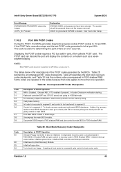
... boot sector code. Initialize floppy drive. Intel® Entry Server Board SE7221BA1-E TPS System BIOS Error Message NVRAM/CMOS/PASSWORD cleared by the BIOS. Displaying the POST-codes requires a PCI bus add-in ROM image. Table 28. Init code to be copied to segment 0 and control to be transferred to 4 GB flat mode. Try to main BIOS in segment 0. The POST card can decode the port and display the contents on a medium such as a sevensegment display. Do necessary chipset initialization, start memory...
... boot sector code. Initialize floppy drive. Intel® Entry Server Board SE7221BA1-E TPS System BIOS Error Message NVRAM/CMOS/PASSWORD cleared by the BIOS. Displaying the POST-codes requires a PCI bus add-in ROM image. Table 28. Init code to be copied to segment 0 and control to be transferred to 4 GB flat mode. Try to main BIOS in segment 0. The POST card can decode the port and display the contents on a medium such as a sevensegment display. Do necessary chipset initialization, start memory...
Product Specification
Page 56
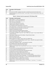
... display the power-on message. Display memory R/W test passed. Booting from ATAPI. POST code to disable cache if any setup required before setting video mode to be done next. CMOS checksum calculation to begin . KB controller I/B free. Chipset init about to be uncompressed. Interrupt vector initialization to begin . 8254 timer test about to boot sector code. To clear password if necessary. To look for optional video ROM and give control to begin. About to start...
... display the power-on message. Display memory R/W test passed. Booting from ATAPI. POST code to disable cache if any setup required before setting video mode to be done next. CMOS checksum calculation to begin . KB controller I/B free. Chipset init about to be uncompressed. Interrupt vector initialization to begin . 8254 timer test about to boot sector code. To clear password if necessary. To look for optional video ROM and give control to begin. About to start...
Product Specification
Page 60
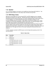
... POST if the video configuration fails (a faulty video card or no card installed) or if an external ROM module does not properly checksum to zero. The BIOS also issues a beep code (one long tone followed by two short tones) during POST, the BIOS displays an error message describing the problem (see Table 34). For more information on the Intel® Entry Server Board SE7221BA1-E. There are several POST routines that external device. Beep Codes Beep 1 3 4 8 Description CPU error Memory error...
... POST if the video configuration fails (a faulty video card or no card installed) or if an external ROM module does not properly checksum to zero. The BIOS also issues a beep code (one long tone followed by two short tones) during POST, the BIOS displays an error message describing the problem (see Table 34). For more information on the Intel® Entry Server Board SE7221BA1-E. There are several POST routines that external device. Beep Codes Beep 1 3 4 8 Description CPU error Memory error...


