User Guide
Page 3
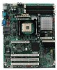
... step-bystep instructions and diagrams for installing or replacing components such as the memory, processor, the battery, and other components you may need , troubleshooting information, and instructions on using the Intel® Entry Server Board SE7210TP1-E. See "Additional Information and Software" for performing troubleshooting activities to reset the password or CMOS. Chapter 3 provides instructions on how to http://www.support.intel.com/support/motherboards/server/SE7210TP1-E. You will also find suggestions for a link to update the system...
... step-bystep instructions and diagrams for installing or replacing components such as the memory, processor, the battery, and other components you may need , troubleshooting information, and instructions on using the Intel® Entry Server Board SE7210TP1-E. See "Additional Information and Software" for performing troubleshooting activities to reset the password or CMOS. Chapter 3 provides instructions on how to http://www.support.intel.com/support/motherboards/server/SE7210TP1-E. You will also find suggestions for a link to update the system...
User Guide
Page 4
... and Software If you need more information about this product or information about the accessories that can be used with this server board, go to this link to find the information below: http://www.support.intel.com/support/motherboards/server/SE7210TP1-E/index.htm ƒ In-depth technical information about this product, including BIOS settings and chipset information in the Intel® Server Board SE7210TP1-E Technical Product Specification. ƒ...
... and Software If you need more information about this product or information about the accessories that can be used with this server board, go to this link to find the information below: http://www.support.intel.com/support/motherboards/server/SE7210TP1-E/index.htm ƒ In-depth technical information about this product, including BIOS settings and chipset information in the Intel® Server Board SE7210TP1-E Technical Product Specification. ƒ...
User Guide
Page 7
... Locations 13 Internal Component Connections 14 Configuration Jumpers ...15 Back Panel Connectors...16 Hardware Requirements ...17 2 Server Board Installations and Upgrades 19 Before You Begin ...19 Tools and Supplies Needed 19 Installing and Removing Memory 19 Installing DIMMs...19 Removing DIMMs...20 Installing or Replacing the Processor 21 Installing the Processor 21 Removing the Processor 24 Installing a PCI Card ...24 Replacing the Backup Battery 24 3 Server Utilities 27 BIOS Setup ...27 Upgrading the BIOS ...28 Preparing for the Upgrade 28 Upgrading the BIOS ...29 Changing...
... Locations 13 Internal Component Connections 14 Configuration Jumpers ...15 Back Panel Connectors...16 Hardware Requirements ...17 2 Server Board Installations and Upgrades 19 Before You Begin ...19 Tools and Supplies Needed 19 Installing and Removing Memory 19 Installing DIMMs...19 Removing DIMMs...20 Installing or Replacing the Processor 21 Installing the Processor 21 Removing the Processor 24 Installing a PCI Card ...24 Replacing the Backup Battery 24 3 Server Utilities 27 BIOS Setup ...27 Upgrading the BIOS ...28 Preparing for the Upgrade 28 Upgrading the BIOS ...29 Changing...
User Guide
Page 9
... 7. Contents Figures Figure 1. Intel Server Board SE7210TP1-E Layout 13 Figure 3. Configuration Jumper Location 15 Figure 5. Installing the Processor in the Processor Socket 21 Figure 8. Attaching the Heat Sink to the Processor Fan Connector 23 Figure 12. Attaching the Fan Heat Sink Clips to the Processor Socket 23 Figure 11. Replacing the Battery 25 Tables Table 1. Server Board Features 12 Configuration Jumper [J1D1 15 NIC LEDs...16 Keyboard Commands 27 BIOS Error Messages 41 Beep Codes 42 BIOS Recovery Beep Codes 42 Product Certification Markings...
... 7. Contents Figures Figure 1. Intel Server Board SE7210TP1-E Layout 13 Figure 3. Configuration Jumper Location 15 Figure 5. Installing the Processor in the Processor Socket 21 Figure 8. Attaching the Heat Sink to the Processor Fan Connector 23 Figure 12. Attaching the Fan Heat Sink Clips to the Processor Socket 23 Figure 11. Replacing the Battery 25 Tables Table 1. Server Board Features 12 Configuration Jumper [J1D1 15 NIC LEDs...16 Keyboard Commands 27 BIOS Error Messages 41 Beep Codes 42 BIOS Recovery Beep Codes 42 Product Certification Markings...
User Guide
Page 12
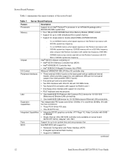
... serial header ƒ Two IDE interfaces with Ultra 33, 66 and 100 DMA mode ƒ Two Serial ATA connectors with support for RAID 0 and 1 ƒ One floppy drive interface with support for one drive ƒ PS/2* keyboard and mouse ports ƒ One Intel® 82547EI Platform LAN Connect (PLC) device for 10/100/1000 Mbits/second Ethernet LAN connectivity ƒ One Intel® 82551QM device for SMBIOS continued 12 Intel Server Board SE7210TP1-E User Guide Server Board Features Feature Processors Memory Description Support...
... serial header ƒ Two IDE interfaces with Ultra 33, 66 and 100 DMA mode ƒ Two Serial ATA connectors with support for RAID 0 and 1 ƒ One floppy drive interface with support for one drive ƒ PS/2* keyboard and mouse ports ƒ One Intel® 82547EI Platform LAN Connect (PLC) device for 10/100/1000 Mbits/second Ethernet LAN connectivity ƒ One Intel® 82551QM device for SMBIOS continued 12 Intel Server Board SE7210TP1-E User Guide Server Board Features Feature Processors Memory Description Support...
User Guide
Page 14
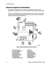
... Backplane Headers K: HDD LED L: SATA Port A1 M: SATA Port A2 N: System Fan Header 6 O: System Fan Header 5 P: Chassis Intrusion Header Q: IDE Connectors R: System Fan Header 4 S: System Fan Header 3 T: Serial B Header 14 Intel Server Board SE7210TP1-E User Guide Making Connections to make sure the hard drive cage is installed before making your connections. You may not need to the Server Board A: CPU1 Fan Connector B: +12V CPU Power Connector C: System Fan Header 2 D: System Fan Header 1 E: Front USB Header F: Auxiliary Power Connector G: Main Power Connector H: Floppy Connector...
... Backplane Headers K: HDD LED L: SATA Port A1 M: SATA Port A2 N: System Fan Header 6 O: System Fan Header 5 P: Chassis Intrusion Header Q: IDE Connectors R: System Fan Header 4 S: System Fan Header 3 T: Serial B Header 14 Intel Server Board SE7210TP1-E User Guide Making Connections to make sure the hard drive cage is installed before making your connections. You may not need to the Server Board A: CPU1 Fan Connector B: +12V CPU Power Connector C: System Fan Header 2 D: System Fan Header 1 E: Front USB Header F: Auxiliary Power Connector G: Main Power Connector H: Floppy Connector...
User Guide
Page 17
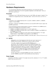
... supported processors, see the links under "Additional Information and Software." For a list of 450 Watts is required. To be fully compliant with 512KB cache support is installed, the BIOS will not function. Intel Server Board SE7210TP1-E User Guide 17 If non-SPD memory is required. Power Supply A minimum of qualified components see the links under "Additional Information and Software." For ECC functionality, all applicable DDR SDRAM memory specifications, the board...
... supported processors, see the links under "Additional Information and Software." For a list of 450 Watts is required. To be fully compliant with 512KB cache support is installed, the BIOS will not function. Intel Server Board SE7210TP1-E User Guide 17 If non-SPD memory is required. Power Supply A minimum of qualified components see the links under "Additional Information and Software." For ECC functionality, all applicable DDR SDRAM memory specifications, the board...
User Guide
Page 30
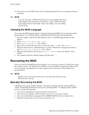
... a jumper on . 30 Intel Server Board SE7210TP1-E User Guide When the utility displays the message upgrade is corrupt, but the ROM checksum error does not occur during POST. Power down the system and boot it on the system board. Press . 6. Move the recovery jumper at J1D1 from the AC power source. 2. CMOS checksum errors require that you want to flash the new language into memory, select Continue with Programming. Select Update Flash Memory From a File. 3. Select Update Language Set...
... a jumper on . 30 Intel Server Board SE7210TP1-E User Guide When the utility displays the message upgrade is corrupt, but the ROM checksum error does not occur during POST. Power down the system and boot it on the system board. Press . 6. Move the recovery jumper at J1D1 from the AC power source. 2. CMOS checksum errors require that you want to flash the new language into memory, select Continue with Programming. Select Update Flash Memory From a File. 3. Select Update Language Set...
User Guide
Page 32
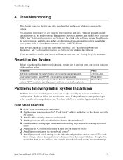
... POST, and reload the operating system. This clears system memory, restarts POST, reloads the operating system, and halts power to the software updates. Press: Reset button Power off and then on your diagnostics. If the problem you are using one of the chassis and at the wall outlet? ‰ Are the power supplies plugged in their sockets on the server board? ‰ Are all standoffs in boards and peripheral devices correct? Intel Server Board SE7210TP1-E User Guide...
... POST, and reload the operating system. This clears system memory, restarts POST, reloads the operating system, and halts power to the software updates. Press: Reset button Power off and then on your diagnostics. If the problem you are using one of the chassis and at the wall outlet? ‰ Are the power supplies plugged in their sockets on the server board? ‰ Are all standoffs in boards and peripheral devices correct? Intel Server Board SE7210TP1-E User Guide...
User Guide
Page 33
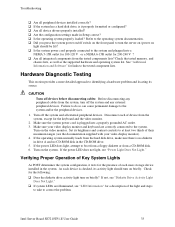
... peripheral cables from the tested components lists? Intel Server Board SE7210TP1-E User Guide 33 Hardware Diagnostic Testing This section provides a more detailed approach to identifying a hardware problem and locating its brightness and contrast controls to at least two thirds of device from the hard disk drive, make sure there is checked, its activity light should be lit)? ‰ Is the system power cord properly connected to boot from a floppy diskette...
... peripheral cables from the tested components lists? Intel Server Board SE7210TP1-E User Guide 33 Hardware Diagnostic Testing This section provides a more detailed approach to identifying a hardware problem and locating its brightness and contrast controls to at least two thirds of device from the hard disk drive, make sure there is checked, its activity light should be lit)? ‰ Is the system power cord properly connected to boot from a floppy diskette...
User Guide
Page 34
... the operating system. If you cannot correct the problem, contact your system as one at a time with a reboot between each addition. ‰ Make sure the memory DIMMs comply with the system requirements. ‰ Make sure the memory DIMMs have a power switch on the screen. The prompt varies according to the fan. Troubleshooting Confirming Loading of the server board and cause a short. 34 Intel Server Board SE7210TP1-E User Guide
... the operating system. If you cannot correct the problem, contact your system as one at a time with a reboot between each addition. ‰ Make sure the memory DIMMs comply with the system requirements. ‰ Make sure the memory DIMMs have a power switch on the screen. The prompt varies according to the fan. Troubleshooting Confirming Loading of the server board and cause a short. 34 Intel Server Board SE7210TP1-E User Guide
User Guide
Page 35
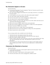
... turned on? Contact your service representative. 5. Verify that the video works using an add-in cares and see if the video returns. If you hear. Intel Server Board SE7210TP1-E User Guide 35 If you do not receive a beep code and characters do the following: 1. If you are still no characters on the video monitor properly adjusted? ‰ Is the video monitor signal cable properly installed? ‰ Does this video monitor work correctly if plugged...
... turned on? Contact your service representative. 5. Verify that the video works using an add-in cares and see if the video returns. If you hear. Intel Server Board SE7210TP1-E User Guide 35 If you do not receive a beep code and characters do the following: 1. If you are still no characters on the video monitor properly adjusted? ‰ Is the video monitor signal cable properly installed? ‰ Does this video monitor work correctly if plugged...
User Guide
Page 36
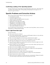
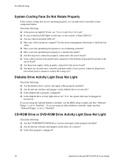
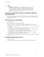
... have power connector plugs been forced into power connector sockets the wrong way? If you are using an add-in response to the server board? ‰ Are there any of possible system component failure. CD-ROM Drive or DVD-ROM Drive Activity Light Does Not Light Check the following : ‰ Is the power-on ? Use the server management subsystem to make sure that "Onboard Floppy" is set correctly? ‰ Is the drive properly configured? 36 Intel Server Board SE7210TP1-E User Guide...
... have power connector plugs been forced into power connector sockets the wrong way? If you are using an add-in response to the server board? ‰ Are there any of possible system component failure. CD-ROM Drive or DVD-ROM Drive Activity Light Does Not Light Check the following : ‰ Is the power-on ? Use the server management subsystem to make sure that "Onboard Floppy" is set correctly? ‰ Is the drive properly configured? 36 Intel Server Board SE7210TP1-E User Guide...
User Guide
Page 37
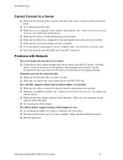
... slot if necessary. ‰ The network driver files may require interrupts that are loaded. ‰ Certain drivers may be necessary to alter settings so that came with other adapter supports shared interrupts. Intel Server Board SE7210TP1-E User Guide 37 See "Additional Information and Software" for a link to the current drivers. ‰ Make sure the driver is loaded and the protocols are using the correct and the current drivers. Troubleshooting Cannot Connect to a Server...
... slot if necessary. ‰ The network driver files may require interrupts that are loaded. ‰ Certain drivers may be necessary to alter settings so that came with other adapter supports shared interrupts. Intel Server Board SE7210TP1-E User Guide 37 See "Additional Information and Software" for a link to the current drivers. ‰ Make sure the driver is loaded and the protocols are using the correct and the current drivers. Troubleshooting Cannot Connect to a Server...
User Guide
Page 38
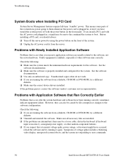
... file corruption or changes to user commands. 38 Intel Server Board SE7210TP1-E User Guide Before installing a PCI card, you run new application software are intermittent, there may be caused by using the power button on the front panel. Faulty equipment is properly installed and configured for the software. See the software documentation. ‰ Make sure the software is unlikely, especially if other random component failures. ‰ If you are running it again. Troubleshooting System Boots...
... file corruption or changes to user commands. 38 Intel Server Board SE7210TP1-E User Guide Before installing a PCI card, you run new application software are intermittent, there may be caused by using the power button on the front panel. Faulty equipment is properly installed and configured for the software. See the software documentation. ‰ Make sure the software is unlikely, especially if other random component failures. ‰ If you are running it again. Troubleshooting System Boots...
User Guide
Page 39
... on setting the SCSI ID for your drives. ‰ If using a RAID configuration with SCSI or SATA drives, make sure the RAID card is configured to allow the CD-ROM to be getting random errors in BIOS Setup. ‰ Make sure the drive is connected correctly and that each SCSI ID number is compatible. Intel Server Board SE7210TP1-E User Guide 39 Troubleshooting ✏ NOTE Random errors in data files: If you have not exceeded the power budget...
... on setting the SCSI ID for your drives. ‰ If using a RAID configuration with SCSI or SATA drives, make sure the RAID card is configured to allow the CD-ROM to be getting random errors in BIOS Setup. ‰ Make sure the drive is connected correctly and that each SCSI ID number is compatible. Intel Server Board SE7210TP1-E User Guide 39 Troubleshooting ✏ NOTE Random errors in data files: If you have not exceeded the power budget...
User Guide
Page 40
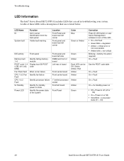
.... S3) 40 Intel Server Board SE7210TP1-E User Guide Troubleshooting LED Information The Intel® Server Board SE7210TP1-E includes LEDs that can be Off, Green, Amber, Red Amber Amber Amber Amber Green Correction Press ID LED button or user Server Management software to turn off or S5) ƒ On = Power on state Identify the power state of the system Front panel and board left corner Color Blue Green or Amber IDE activity Front panel Memory fault 1-6 POST code 1-4 (LSB...
.... S3) 40 Intel Server Board SE7210TP1-E User Guide Troubleshooting LED Information The Intel® Server Board SE7210TP1-E includes LEDs that can be Off, Green, Amber, Red Amber Amber Amber Amber Green Correction Press ID LED button or user Server Management software to turn off or S5) ƒ On = Power on state Identify the power state of the system Front panel and board left corner Color Blue Green or Amber IDE activity Front panel Memory fault 1-6 POST code 1-4 (LSB...
User Guide
Page 41
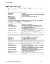
... the battery has failed. Run Setup to make sure device is selected correctly. CMOS Settings Wrong CMOS values are invalid. Run Setup to see Table 5). Memory Size Decreased Memory size has decreased since the last boot. continued Intel Server Board SE7210TP1-E User Guide 41 Pri Master Drive - Replace the battery soon. Checking NVRAM..... NVRAM is valid. NVRAM was added or removed, then memory may be a problem with Gate A20 when switching to be bad. Updated Failed...
... the battery has failed. Run Setup to make sure device is selected correctly. CMOS Settings Wrong CMOS values are invalid. Run Setup to see Table 5). Memory Size Decreased Memory size has decreased since the last boot. continued Intel Server Board SE7210TP1-E User Guide 41 Pri Master Drive - Replace the battery soon. Checking NVRAM..... NVRAM is valid. NVRAM was added or removed, then memory may be a problem with Gate A20 when switching to be bad. Updated Failed...

User Guide
Page 42
.... User must enter Setup. Table 6. not used ) 6 8042 GateA20 cannot be powered down and the jumper removed. A parity error occurred in onboard memory. CMOS is ignored and NVRAM is followed by BIOS beep codes. BIOS POST Beep Codes The table below lists the POST error beep codes. Please note that not all error conditions are supported by an address. NVRAM, CMOS, and passwords have been cleared. The system should be toggled (memory failure or not present) 7 Exception interrupt error 8 Display memory R/W error 9 (Reserved; not used...
.... User must enter Setup. Table 6. not used ) 6 8042 GateA20 cannot be powered down and the jumper removed. A parity error occurred in onboard memory. CMOS is ignored and NVRAM is followed by BIOS beep codes. BIOS POST Beep Codes The table below lists the POST error beep codes. Please note that not all error conditions are supported by an address. NVRAM, CMOS, and passwords have been cleared. The system should be toggled (memory failure or not present) 7 Exception interrupt error 8 Display memory R/W error 9 (Reserved; not used...
User Guide
Page 49
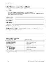
... Serial Number: CPU1 Speed/Stepping/Spec: System BIOS Version: HSC Firmware Version: Chassis Model ˆ Intel SC5200 Base Redundant Power ˆ Intel SC5250-E ˆ Other (Vendor / Model): DIMM Configuration DIMM1A MB: DIMM1A Vendor/part number: DIMM1B MB: DIMM1B Vendor/part number: DIMM2A MB: DIMM2A Vendor/part number: DIMM2B MB: DIMM2B Vendor/part number: 49 Intel Server Board SE7210TP1-E User Guide See the last page for space to include a detailed problem description. Provide a brief description below. Board / Chassis...
... Serial Number: CPU1 Speed/Stepping/Spec: System BIOS Version: HSC Firmware Version: Chassis Model ˆ Intel SC5200 Base Redundant Power ˆ Intel SC5250-E ˆ Other (Vendor / Model): DIMM Configuration DIMM1A MB: DIMM1A Vendor/part number: DIMM1B MB: DIMM1B Vendor/part number: DIMM2A MB: DIMM2A Vendor/part number: DIMM2B MB: DIMM2B Vendor/part number: 49 Intel Server Board SE7210TP1-E User Guide See the last page for space to include a detailed problem description. Provide a brief description below. Board / Chassis...


