Product Guide
Page 4
... 49 DIMM Installation Guidelines 49 Installing DIMMs...50 Removing DIMMs...51 Installing and Removing an AGP Card 51 Installing an AGP Card 52 Removing the AGP Card 52 Connecting the IDE Cable...53 Connecting the Serial ATA Cable (Optional 54 Connecting Internal Headers 55 Connecting the Front Panel Header 55 Connecting the USB 2.0 Header 56 Connecting Hardware Control and Power Cables 57 Connecting Fans ...58 Chassis Intrusion...58 Connecting Power Cables 58 Setting the BIOS Configuration Jumper 58 Clearing Passwords ...59 Replacing the Battery...60 iv Intel Server Board S875WP1...
... 49 DIMM Installation Guidelines 49 Installing DIMMs...50 Removing DIMMs...51 Installing and Removing an AGP Card 51 Installing an AGP Card 52 Removing the AGP Card 52 Connecting the IDE Cable...53 Connecting the Serial ATA Cable (Optional 54 Connecting Internal Headers 55 Connecting the Front Panel Header 55 Connecting the USB 2.0 Header 56 Connecting Hardware Control and Power Cables 57 Connecting Fans ...58 Chassis Intrusion...58 Connecting Power Cables 58 Setting the BIOS Configuration Jumper 58 Clearing Passwords ...59 Replacing the Battery...60 iv Intel Server Board S875WP1...
Product Guide
Page 5
... Chipset Configuration Submenu 83 Fan Control Configuration Submenu 85 Hardware Monitoring Submenu 86 Remote Access Configuration Submenu 87 Security Menu ...88 Power Menu ...89 ACPI Submenu 89 Boot Menu ...90 Boot Device Priority Submenu 91 Hard Disk Drives Submenu 91 Removable Devices Submenu 92 ATAPI CDROM Drives Submenu 92 Exit Menu ...93 4 Solving BIOS Problems 95 BIOS Beep Codes...95 BIOS Error Messages ...96 5 Getting Help 99 World Wide Web ...99 Telephone ...99 6 Technical Reference 101 Server Board Connectors...101 Baseboard Connectors 102 Power, Fan, Chassis...
... Chipset Configuration Submenu 83 Fan Control Configuration Submenu 85 Hardware Monitoring Submenu 86 Remote Access Configuration Submenu 87 Security Menu ...88 Power Menu ...89 ACPI Submenu 89 Boot Menu ...90 Boot Device Priority Submenu 91 Hard Disk Drives Submenu 91 Removable Devices Submenu 92 ATAPI CDROM Drives Submenu 92 Exit Menu ...93 4 Solving BIOS Problems 95 BIOS Beep Codes...95 BIOS Error Messages ...96 5 Getting Help 99 World Wide Web ...99 Telephone ...99 6 Technical Reference 101 Server Board Connectors...101 Baseboard Connectors 102 Power, Fan, Chassis...
Product Guide
Page 7
... Server Board 45 Figure 11. Connecting the IDE Cable 53 Figure 19. BIOS Configuration Jumper Block Location 58 Figure 23. Removing the Battery 62 Figure 24. Table 4. Table 10. Table 11. Table 20. Location of Pressing the Power Switch under ACPI 25 Wake-up Devices and Events 26 Fan Connector Function/Operation 28 Supervisor and User Password Functions 31 Front Panel Header (J7J1 55 USB 2.0 Header (J7E1 56 Jumper Settings for the BIOS Setup Program Modes (J8J2 59 BIOS Setup Program Menu...
... Server Board 45 Figure 11. Connecting the IDE Cable 53 Figure 19. BIOS Configuration Jumper Block Location 58 Figure 23. Removing the Battery 62 Figure 24. Table 4. Table 10. Table 11. Table 20. Location of Pressing the Power Switch under ACPI 25 Wake-up Devices and Events 26 Fan Connector Function/Operation 28 Supervisor and User Password Functions 31 Front Panel Header (J7J1 55 USB 2.0 Header (J7E1 56 Jumper Settings for the BIOS Setup Program Modes (J8J2 59 BIOS Setup Program Menu...
Product Guide
Page 9
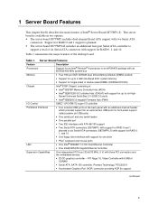
... Processors Support for an Intel® Pentium® 4 processor in two options: • The server board S875WP1 includes dual-channel Serial ATA support with support for up to support a total of six Serial ATA connectors with three PCI connectors and two embedded devices: • 2D/3D graphics controller - ATI Rage* XL Video Controller with 8 MB of the desktop board. Table 1 summarizes the major features of SDRAM • Serial ATA: SATA-150 controller, Promise Technology* PDC20319 • Accelerated Graphics Port (AGP) connector...
... Processors Support for an Intel® Pentium® 4 processor in two options: • The server board S875WP1 includes dual-channel Serial ATA support with support for up to support a total of six Serial ATA connectors with three PCI connectors and two embedded devices: • 2D/3D graphics controller - ATI Rage* XL Video Controller with 8 MB of the desktop board. Table 1 summarizes the major features of SDRAM • Serial ATA: SATA-150 controller, Promise Technology* PDC20319 • Accelerated Graphics Port (AGP) connector...
Product Guide
Page 11
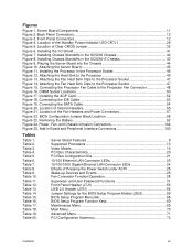
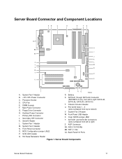
DIMM Sockets F. Floppy Drive Connector H. Secondary IDE Connector K. System Fan 1 Header M. Clear CMOS Jumper J8G1 Y. SATA-B1 and SATA-B2 Connectors (slots numbered from left to right: SATA-A4, SATA-A2, SATA-A3, SATA-A1) T. Processor Socket D. CPU Fan E. SCSI LED Header S. System Fan 3 Header W. Back Panel I . Chassis Intrusion Header U. NIC1 (1 Gb) CC. Serial B Header L. Front Panel USB Header X. NIC2 (10/100 Mb) BB. Hot Swap Backplane Header Figure 1. Battery RQ TP00182 B. +12V CPU Power Connector C. System Fan 2 Header N. AGP Connector AA. PCI...
DIMM Sockets F. Floppy Drive Connector H. Secondary IDE Connector K. System Fan 1 Header M. Clear CMOS Jumper J8G1 Y. SATA-B1 and SATA-B2 Connectors (slots numbered from left to right: SATA-A4, SATA-A2, SATA-A3, SATA-A1) T. Processor Socket D. CPU Fan E. SCSI LED Header S. System Fan 3 Header W. Back Panel I . Chassis Intrusion Header U. NIC1 (1 Gb) CC. Serial B Header L. Front Panel USB Header X. NIC2 (10/100 Mb) BB. Hot Swap Backplane Header Figure 1. Battery RQ TP00182 B. +12V CPU Power Connector C. System Fan 2 Header N. AGP Connector AA. PCI...
Product Guide
Page 15
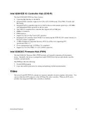
...; Integrated LAN controller (Intel 8562ET) for interfacing the ICH5-R LAN connect interface to the LAN connect component • 33 MHz Peripheral Component Interface (PCI) Local Bus slots supporting PCI specification, Rev 2.3. • Power management logic (ACPI Rev 2.0-compliant). • Support for storing and updating of platform information Video The server board S875WP1-E contains two separate, mutually exclusive graphics subsystems. You can use either the AGP connector or the ATI Rage XL video controller. Internally, the device is disabled.
...; Integrated LAN controller (Intel 8562ET) for interfacing the ICH5-R LAN connect interface to the LAN connect component • 33 MHz Peripheral Component Interface (PCI) Local Bus slots supporting PCI specification, Rev 2.3. • Power management logic (ACPI Rev 2.0-compliant). • Support for storing and updating of platform information Video The server board S875WP1-E contains two separate, mutually exclusive graphics subsystems. You can use either the AGP connector or the ATI Rage XL video controller. Internally, the device is disabled.
Product Guide
Page 16
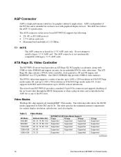
... monitors up to 1024 x 768 resolution in 8/16/24/32 bpp modes under 2D, and up to install a legacy 3.3 V AGP card. AGP is independent of the PCI slots. The AGP connector on -board video through the BIOS Setup menu or when a plug-in the AGP slot or any of the PCI bus and is installed in video card is intended for exclusive use with graphical display devices. Video Modes The Rage XL chip supports all standard IBM* VGA modes. Video Modes 2D Mode...
... monitors up to 1024 x 768 resolution in 8/16/24/32 bpp modes under 2D, and up to install a legacy 3.3 V AGP card. AGP is independent of the PCI slots. The AGP connector on -board video through the BIOS Setup menu or when a plug-in the AGP slot or any of the PCI bus and is installed in video card is intended for exclusive use with graphical display devices. Video Modes The Rage XL chip supports all standard IBM* VGA modes. Video Modes 2D Mode...
Product Guide
Page 18
... is located on the back panel. Power to 115.2 kb/s with the 82077 diskette drive controller and supports both PC-AT and PS/2 modes. A power-on /reset. The serial ports' NS16C550-compatible UART supports data transfers at speeds up to the computer should be specified in the BIOS Setup program. 18 Intel Server Board S875WP1-E Product Guide In the BIOS Setup program, the parallel port can be turned off before a keyboard or mouse is supported in...
... is located on the back panel. Power to 115.2 kb/s with the 82077 diskette drive controller and supports both PC-AT and PS/2 modes. A power-on /reset. The serial ports' NS16C550-compatible UART supports data transfers at speeds up to the computer should be specified in the BIOS Setup program. 18 Intel Server Board S875WP1-E Product Guide In the BIOS Setup program, the parallel port can be turned off before a keyboard or mouse is supported in...
Product Guide
Page 20
... operating system loads the USB drivers, all legacy and non-legacy USB devices are recognized by the BIOS allowing the user to use a USB keyboard to enter and configure the BIOS Setup program and the maintenance menu. 4. The PCI bus complies with one independent PCI bus. POST completes. 5. Other USB devices are not recognized during this period if Legacy USB support is set to disable the device. 20 Intel Server Board S875WP1-E Product Guide The table below lists the characteristics of the embedded devices listed above, with...
... operating system loads the USB drivers, all legacy and non-legacy USB devices are recognized by the BIOS allowing the user to use a USB keyboard to enter and configure the BIOS Setup program and the maintenance menu. 4. The PCI bus complies with one independent PCI bus. POST completes. 5. Other USB devices are not recognized during this period if Legacy USB support is set to disable the device. 20 Intel Server Board S875WP1-E Product Guide The table below lists the characteristics of the embedded devices listed above, with...
Product Guide
Page 22
... board supports Laser Servo (LS-120) diskette technology through the IDE interfaces. An LS-120 drive can be configured as CD-ROM drives) and ATA devices using the transfer modes. floppy disk drive) • ARMD-HDD (ATAPI removable media device - The interface handles the exchange of the following: • ARMD-FDD (ATAPI removable media device - The LED indicates when data is a 1 x 2-pin connector that can be independently enabled. hard disk drive) SCSI Hard Drive Activity LED Connector The SCSI hard drive activity LED connector...
... board supports Laser Servo (LS-120) diskette technology through the IDE interfaces. An LS-120 drive can be configured as CD-ROM drives) and ATA devices using the transfer modes. floppy disk drive) • ARMD-HDD (ATAPI removable media device - The interface handles the exchange of the following: • ARMD-FDD (ATAPI removable media device - The LED indicates when data is a 1 x 2-pin connector that can be independently enabled. hard disk drive) SCSI Hard Drive Activity LED Connector The SCSI hard drive activity LED connector...
Product Guide
Page 33
... be updated using a disk-based program. PCI Auto Configuration The BIOS can override the auto-configuration options by the add-in the BIOS Setup program. Server Board Features 33 Replace the chassis cover and re-attach the AC power cables. 8. When the S875WP1-E server board's jumper is set to PIO Mode 3 or 4, depending on the system after adding a PCI card, the BIOS automatically configures interrupts, the I /O channel support. The IDE interface supports hard drives up , the BIOS compares the processor version and the microcode version in...
... be updated using a disk-based program. PCI Auto Configuration The BIOS can override the auto-configuration options by the add-in the BIOS Setup program. Server Board Features 33 Replace the chassis cover and re-attach the AC power cables. 8. When the S875WP1-E server board's jumper is set to PIO Mode 3 or 4, depending on the system after adding a PCI card, the BIOS automatically configures interrupts, the I /O channel support. The IDE interface supports hard drives up , the BIOS compares the processor version and the microcode version in...
Product Guide
Page 59
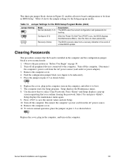
Turn off the computer. Place the jumper on pins 2-3 as shown below . 13 6. Server Board Installation and Upgrades 59 Jumper Settings for the BIOS Setup Program Modes (J8J2) Jumper Setting 13 13 Mode Normal (default) (1-2) Description The BIOS uses the current configuration and passwords for the Setup program modes. Use this menu to clear passwords. 13 Recovery (None) The BIOS recovers data from a recovery diskette in the computer and the configuration jumper block is installed in the event of a failed BIOS update. Clearing Passwords This procedure...
Turn off the computer. Place the jumper on pins 2-3 as shown below . 13 6. Server Board Installation and Upgrades 59 Jumper Settings for the BIOS Setup Program Modes (J8J2) Jumper Setting 13 13 Mode Normal (default) (1-2) Description The BIOS uses the current configuration and passwords for the Setup program modes. Use this menu to clear passwords. 13 Recovery (None) The BIOS recovers data from a recovery diskette in the computer and the configuration jumper block is installed in the event of a failed BIOS update. Clearing Passwords This procedure...
Product Guide
Page 68
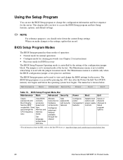
... (POST) memory test begins and before the operating system boot begins. This chapter tells you how to access the BIOS Setup program and lists Setup features, options, and default settings. ✏ NOTE For reference purposes, you make changes to the Intel Web site at the factory. Using the Setup Program You can be used with the jumper in normal mode. BIOS Setup Program Menu Bar Maintenance Main Advanced Security Clears passwords and Boot Integrity Service (BIS...
... (POST) memory test begins and before the operating system boot begins. This chapter tells you how to access the BIOS Setup program and lists Setup features, options, and default settings. ✏ NOTE For reference purposes, you make changes to the Intel Web site at the factory. Using the Setup Program You can be used with the jumper in normal mode. BIOS Setup Program Menu Bar Maintenance Main Advanced Security Clears passwords and Boot Integrity Service (BIS...
Product Guide
Page 76
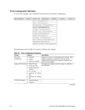
...be installed. When Enhanced is selected, a maximum of 6 drives can be installed. Maintenance Main Advanced Security Power PCI Configuration Boot Configuration Peripheral Configuration Drive Configuration Floppy Configuration Event Log Configuration Video Configuration USB Configuration Chipset Configuration Fan Control Configuration Hardware Monitoring Remote Access Configuration Boot Exit The menu represented in Table 23 is selected as the IDE Mode. PCI IDE Bus Master • Enabled (default) • Disabled continued 76 Intel Server Board S875WP1-E Product Guide
...be installed. When Enhanced is selected, a maximum of 6 drives can be installed. Maintenance Main Advanced Security Power PCI Configuration Boot Configuration Peripheral Configuration Drive Configuration Floppy Configuration Event Log Configuration Video Configuration USB Configuration Chipset Configuration Fan Control Configuration Hardware Monitoring Remote Access Configuration Boot Exit The menu represented in Table 23 is selected as the IDE Mode. PCI IDE Bus Master • Enabled (default) • Disabled continued 76 Intel Server Board S875WP1-E Product Guide
Product Guide
Page 77
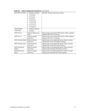
... Select to display sub-menu Reports type of connected IDE device. Drive Configuration Submenu (continued) Hard Disk Pre-Delay • Disabled (default) Specifies the hard disk drive pre-delay. • 3 Seconds • 6 Seconds • 9 Seconds • 12 Seconds • 15 Seconds • 21 Seconds • 30 Seconds Intel (R) RAID Technology • Disabled (default) • Enabled SATA Port -0 Select to display sub-menu Reports type of connected SATA device. SATA Port -1 Select to display submenu Reports type of connected SATA device. PATA Secondary...
... Select to display sub-menu Reports type of connected IDE device. Drive Configuration Submenu (continued) Hard Disk Pre-Delay • Disabled (default) Specifies the hard disk drive pre-delay. • 3 Seconds • 6 Seconds • 9 Seconds • 12 Seconds • 15 Seconds • 21 Seconds • 30 Seconds Intel (R) RAID Technology • Disabled (default) • Enabled SATA Port -0 Select to display sub-menu Reports type of connected SATA device. SATA Port -1 Select to display submenu Reports type of connected SATA device. PATA Secondary...
Product Guide
Page 79
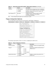
...; Disabled (default) • Enabled Disables or enables the integrated diskette controller. Enables or disables Self-monitoring, Analysis, and Reporting Technology. Floppy Configuration Submenu To access this option is not displayed. Table 25. If Auto is used for the diskette drive. Maintenance Main Advanced Security Power Boot PCI Configuration Boot Configuration Peripheral Configuration Drive Configuration Floppy Configuration Event Log Configuration Video Configuration USB Configuration Chipset Configuration Fan Control Configuration Hardware Monitoring...
...; Disabled (default) • Enabled Disables or enables the integrated diskette controller. Enables or disables Self-monitoring, Analysis, and Reporting Technology. Floppy Configuration Submenu To access this option is not displayed. Table 25. If Auto is used for the diskette drive. Maintenance Main Advanced Security Power Boot PCI Configuration Boot Configuration Peripheral Configuration Drive Configuration Floppy Configuration Event Log Configuration Video Configuration USB Configuration Chipset Configuration Fan Control Configuration Hardware Monitoring...
Product Guide
Page 82
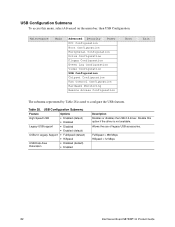
...8226; Disabled (default) • Enabled Description Enables or disables the USB 2.0 driver. Disable this menu, select Advanced on the menu bar, then USB Configuration. Maintenance Main Advanced Security Power PCI Configuration Boot Configuration Peripheral Configuration Drive Configuration Floppy Configuration Event Log Configuration Video Configuration USB Configuration Chipset Configuration Fan Control Configuration Hardware Monitoring Remote Access Configuration Boot Exit The submenu represented by Table 28 is not available. Table 28. Allows the use of legacy USB accessories...
...8226; Disabled (default) • Enabled Description Enables or disables the USB 2.0 driver. Disable this menu, select Advanced on the menu bar, then USB Configuration. Maintenance Main Advanced Security Power PCI Configuration Boot Configuration Peripheral Configuration Drive Configuration Floppy Configuration Event Log Configuration Video Configuration USB Configuration Chipset Configuration Fan Control Configuration Hardware Monitoring Remote Access Configuration Boot Exit The submenu represented by Table 28 is not available. Table 28. Allows the use of legacy USB accessories...
Product Guide
Page 88
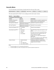
... Power Boot Exit The menu represented by Table 33 is for user level. alphanumeric characters. Sets BIOS Setup Utility access rights for setting passwords and security features. Full: User can change any changes. No Access: User cannot access BIOS Setup. Security Menu To access this menu, select Security from the menu bar at the top of the screen. User Password Is No options Reports if there is a supervisor password set . 88 Intel Server Board S875WP1-E Product Guide Table 33. Set User Password Clear User Password (Note 1) User Access Level (Note 2) Password...
... Power Boot Exit The menu represented by Table 33 is for user level. alphanumeric characters. Sets BIOS Setup Utility access rights for setting passwords and security features. Full: User can change any changes. No Access: User cannot access BIOS Setup. Security Menu To access this menu, select Security from the menu bar at the top of the screen. User Password Is No options Reports if there is a supervisor password set . 88 Intel Server Board S875WP1-E Product Guide Table 33. Set User Password Clear User Password (Note 1) User Access Level (Note 2) Password...
Product Guide
Page 90
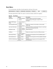
... POST tests. Maintenance Main Advanced Security Power Boot Exit The menu represented in Table 36 is used to display submenu Description Disabled displays normal POST messages. Specifies the boot sequence from the available types of POST messages. Boot Menu To access this menu, select Boot from the menu bar at boot time. Boot Menu Feature Options Silent Boot • Disabled (default) • Enabled AddOn ROM Display Mode Intel® Rapid BIOS Boot Scan User Flash Area PXE Boot to LAN USB Boot Boot Device Priority Removable Devices ATAPI CD-ROM Drives • Enabled (default...
... POST tests. Maintenance Main Advanced Security Power Boot Exit The menu represented in Table 36 is used to display submenu Description Disabled displays normal POST messages. Specifies the boot sequence from the available types of POST messages. Boot Menu To access this menu, select Boot from the menu bar at boot time. Boot Menu Feature Options Silent Boot • Disabled (default) • Enabled AddOn ROM Display Mode Intel® Rapid BIOS Boot Scan User Flash Area PXE Boot to LAN USB Boot Boot Device Priority Removable Devices ATAPI CD-ROM Drives • Enabled (default...
Product Guide
Page 96
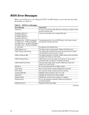
... reset values. Replace the battery soon. Run Setup to make sure type is correct. Keyboard Error Error in CMOS are not the same as the last boot. KB/Interface Error Keyboard interface test failed. FDC Failure Error occurred trying to protected mode during the memory test. BIOS Error Messages Error Message GA20 Error Explanation An error occurred with Gate A20 when switching to access diskette drive controller. Pri Master HDD Error Pri Slave HDD Error Sec Master HDD Error Sec Slave HDD Error...
... reset values. Replace the battery soon. Run Setup to make sure type is correct. Keyboard Error Error in CMOS are not the same as the last boot. KB/Interface Error Keyboard interface test failed. FDC Failure Error occurred trying to protected mode during the memory test. BIOS Error Messages Error Message GA20 Error Explanation An error occurred with Gate A20 when switching to access diskette drive controller. Pri Master HDD Error Pri Slave HDD Error Sec Master HDD Error Sec Slave HDD Error...


