Product Specification
Page 2
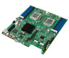
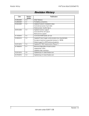
... jumper location figure. Formatting corrections. Corrected processor fault table. Updated memory support. Updated Power Supply communication bus requirements. ii Revision 1.9 Intel order number E53971-008 Corrected USB header pin-out. Added support for 5600 series processors. Updated typo in board feature set . Updated12V SKU board picture (Figure 1). Updated NIC LEDs. Updated typo in board feature set . Removed S4 support. Updated heatsink installation steps. Increased maximum supported memory to 128GB. Updated video resolution. Removed Rapid Boot Toolkit...
... jumper location figure. Formatting corrections. Corrected processor fault table. Updated memory support. Updated Power Supply communication bus requirements. ii Revision 1.9 Intel order number E53971-008 Corrected USB header pin-out. Added support for 5600 series processors. Updated typo in board feature set . Updated12V SKU board picture (Figure 1). Updated NIC LEDs. Updated typo in board feature set . Removed S4 support. Updated heatsink installation steps. Increased maximum supported memory to 128GB. Updated video resolution. Removed Rapid Boot Toolkit...

Product Specification
Page 6
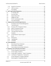
... 6.1.3 BIOS Recovery Mode (J1C3 49 6.1.4 Reset BIOS Configuration (J1B4 50 6.1.5 Video Master (J6A3 50 6.1.6 ME Firmware Force Update (J7A2 51 6.1.7 Serial Interface (J6A2 51 7. Connector/Header Locations and Pin-out 52 7.1 Power Connectors 52 7.2 7.2.1 System Management Headers 54 Intel® Remote Management Module 3 (Intel® RMM3) Connector 54 7.2.2 BMC Power Cycle Header (12V Only 54 7.2.3 Hard Drive Activity (Input) LED Header 55 7.2.4 IPMB Header...55 7.2.5 SGPIO Header ...55 7.3 SSI Control Panel Connector 55 7.3.1 Power Button ...56 7.3.2 Reset Button...
... 6.1.3 BIOS Recovery Mode (J1C3 49 6.1.4 Reset BIOS Configuration (J1B4 50 6.1.5 Video Master (J6A3 50 6.1.6 ME Firmware Force Update (J7A2 51 6.1.7 Serial Interface (J6A2 51 7. Connector/Header Locations and Pin-out 52 7.1 Power Connectors 52 7.2 7.2.1 System Management Headers 54 Intel® Remote Management Module 3 (Intel® RMM3) Connector 54 7.2.2 BMC Power Cycle Header (12V Only 54 7.2.3 Hard Drive Activity (Input) LED Header 55 7.2.4 IPMB Header...55 7.2.5 SGPIO Header ...55 7.3 SSI Control Panel Connector 55 7.3.1 Power Button ...56 7.3.2 Reset Button...
Product Specification
Page 7
...10.3 Power Sequencing and Reset Distribution 84 11. Design and Environmental Specifications 76 9.1 Fan Speed Control Thermal Management 76 9.2 Thermal Sensors 78 9.2.1 Processor PECI Temperature Sensor 78 9.2.2 Memory Temperature Sensor 79 9.2.3 Board Temperature Sensor 79 9.2.4 Thermals Sensor Placement 79 9.3 Heatsinks ...80 9.3.1 Unified Retention System Support 81 9.4 Errors ...82 9.4.1 PROCHOT# ...82 9.4.2 THERMTRIP# ...82 9.4.3 CATERR# ...82 10. Intel® Server Board S5500WB TPS Table of Contents 7.4.6 Serial Port Connectors 66 7.4.7 USB Connectors 66...
...10.3 Power Sequencing and Reset Distribution 84 11. Design and Environmental Specifications 76 9.1 Fan Speed Control Thermal Management 76 9.2 Thermal Sensors 78 9.2.1 Processor PECI Temperature Sensor 78 9.2.2 Memory Temperature Sensor 79 9.2.3 Board Temperature Sensor 79 9.2.4 Thermals Sensor Placement 79 9.3 Heatsinks ...80 9.3.1 Unified Retention System Support 81 9.4 Errors ...82 9.4.1 PROCHOT# ...82 9.4.2 THERMTRIP# ...82 9.4.3 CATERR# ...82 10. Intel® Server Board S5500WB TPS Table of Contents 7.4.6 Serial Port Connectors 66 7.4.7 USB Connectors 66...

Product Specification
Page 11
... 47 Table 18. Video Master Jumper 50 Table 23. Reset BIOS Jumper 50 Table 22. Intel® RMM3 Connector Pin-out (J5B1 54 Table 30. Intel® Server Board S5500WB Feature Set 2 Table 2. Intel® Server Board S5500WB System Interconnects 7 Table 3. Intel® Server Board S5500WB Features 13 Table 4. IOH24D PCI Express* Bus Segments 27 Table 7. RMM3 Features ...34 Table 9. Intel® I /O Expansion Module Product Codes 38 Table 14: BMC...
... 47 Table 18. Video Master Jumper 50 Table 23. Reset BIOS Jumper 50 Table 22. Intel® RMM3 Connector Pin-out (J5B1 54 Table 30. Intel® Server Board S5500WB Feature Set 2 Table 2. Intel® Server Board S5500WB System Interconnects 7 Table 3. Intel® Server Board S5500WB Features 13 Table 4. IOH24D PCI Express* Bus Segments 27 Table 7. RMM3 Features ...34 Table 9. Intel® I /O Expansion Module Product Codes 38 Table 14: BMC...

Product Specification
Page 15
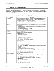
... Board S5500WB is a dual socket server using the Intel® Xeon® Processor 5500 series and 5600 series processors, in combination with the IOH and ICH10R to provide a balanced feature set between technology leadership and cost. 1.1 Section Outline This document is the responsibility of their specific application and environmental conditions. Video POST Code Errors Glossary Reference Documents 1.2 Server Board Use Disclaimer Intel Corporation server boards contain a number of high...
... Board S5500WB is a dual socket server using the Intel® Xeon® Processor 5500 series and 5600 series processors, in combination with the IOH and ICH10R to provide a balanced feature set between technology leadership and cost. 1.1 Section Outline This document is the responsibility of their specific application and environmental conditions. Video POST Code Errors Glossary Reference Documents 1.2 Server Board Use Disclaimer Intel Corporation server boards contain a number of high...
Product Specification
Page 16
.../1000 LAN Internal connections: Two USB 2x5 pin header, supporting four USB 2.0 ports One low-profile USB 2x5 pin One DH-10 Serial Port B header One 2x8 pin VGA header with features designed to support optional Intel® Remote Management Module 3 SATA SW RAID 5 Activation Key Connector One SSI-EEB compliant front panel header SSI SKU One SSI-EEB compliant 24-pin main power connector (SSI only SKU) One SSI compliant 8-pin CPU power connector ...
.../1000 LAN Internal connections: Two USB 2x5 pin header, supporting four USB 2.0 ports One low-profile USB 2x5 pin One DH-10 Serial Port B header One 2x8 pin VGA header with features designed to support optional Intel® Remote Management Module 3 SATA SW RAID 5 Activation Key Connector One SSI-EEB compliant front panel header SSI SKU One SSI-EEB compliant 24-pin main power connector (SSI only SKU) One SSI compliant 8-pin CPU power connector ...
Product Specification
Page 29
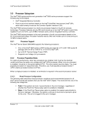
... disabled. Major: If the Post Error Pause setup option is installed, it goes directly to the error manager, regardless of shared cache. 3.3.1 Processor Support The Intel® Server Board S5500WB supports the following processors: One or two Intel® 5500 series or 5600 series processor(s) in sequential order. You must populate processor socket 1 (CPU1) before processor socket 2 (CPU2). The error is the next generation of shared cache, and an integrated memory controller...
... disabled. Major: If the Post Error Pause setup option is installed, it goes directly to the error manager, regardless of shared cache. 3.3.1 Processor Support The Intel® Server Board S5500WB supports the following processors: One or two Intel® 5500 series or 5600 series processor(s) in sequential order. You must populate processor socket 1 (CPU1) before processor socket 2 (CPU2). The error is the next generation of shared cache, and an integrated memory controller...

Product Specification
Page 30
... the Integrated BMC about the configuration error. Does not disable the processor. Displays ―0195: Processor 0x Intel(R) QPI speed mismatch‖ message in the Error Manager. If POST Error Pause is disabled in the Setup, continues to boot the system successfully. Processor microcode missing Minor Processor Intel® QuickPath Halt Interconnect speeds not identical If the frequencies for all processor frequencies to the lowest common denominator...
... the Integrated BMC about the configuration error. Does not disable the processor. Displays ―0195: Processor 0x Intel(R) QPI speed mismatch‖ message in the Error Manager. If POST Error Pause is disabled in the Setup, continues to boot the system successfully. Processor microcode missing Minor Processor Intel® QuickPath Halt Interconnect speeds not identical If the frequencies for all processor frequencies to the lowest common denominator...

Product Specification
Page 41
... Chipset IOH supports DMA remapping from the I /O Card Slots x4 PCI Express* Gen1 throughput to the ICH10R southbridge x4 PCI Express* Gen1 throughput to enable or disable the Virtualization Technology setting in the BIOS processor setup menu. 3.5.1.2 Intel® Virtualization Technology for the discrete Baseboard Management Controller (BMC). This is designed to slot 1. You can enable or disable the Intel® Virtualization Technology in its local caches. It is accomplished by placing the data from inbound PCI Express* memory Guest...
... Chipset IOH supports DMA remapping from the I /O Card Slots x4 PCI Express* Gen1 throughput to the ICH10R southbridge x4 PCI Express* Gen1 throughput to enable or disable the Virtualization Technology setting in the BIOS processor setup menu. 3.5.1.2 Intel® Virtualization Technology for the discrete Baseboard Management Controller (BMC). This is designed to slot 1. You can enable or disable the Intel® Virtualization Technology in its local caches. It is accomplished by placing the data from inbound PCI Express* memory Guest...

Product Specification
Page 43
... to use data stripping to alleviate disk bottlenecks by accessing the BIOS setup utility during POST. 3.7.1.1 Intel® Embedded Server RAID Technology II The onboard storage capability of these server boards includes support for a total of 12 Ports Revision 1.9 29 Intel order number E53971-008 All ports are high-speed, full-speed, and low-speed capable. Four external connectors are numbered SATA-1 through SATA-6. Intel® Server Board S5500WB TPS Functional Architecture server board are located on a replacement drive...
... to use data stripping to alleviate disk bottlenecks by accessing the BIOS setup utility during POST. 3.7.1.1 Intel® Embedded Server RAID Technology II The onboard storage capability of these server boards includes support for a total of 12 Ports Revision 1.9 29 Intel order number E53971-008 All ports are high-speed, full-speed, and low-speed capable. Four external connectors are numbered SATA-1 through SATA-6. Intel® Server Board S5500WB TPS Functional Architecture server board are located on a replacement drive...

Product Specification
Page 48
... I/O panel area of a chassis. RMM3 Features Manageability features Embedded Web U KVM Redirection USB 2.0 Media Redirection Security WS- You can use a standard DH-10 to DB9 cable to direct serial A port to the product. You can support any standard serial device. The system BIOS provides the option for dual-video operation when an add-in video card is a fully-functional serial port that can disable the onboard video controller using a standard 15-pin VGA connector found in video card...
... I/O panel area of a chassis. RMM3 Features Manageability features Embedded Web U KVM Redirection USB 2.0 Media Redirection Security WS- You can use a standard DH-10 to DB9 cable to direct serial A port to the product. You can support any standard serial device. The system BIOS provides the option for dual-video operation when an add-in video card is a fully-functional serial port that can disable the onboard video controller using a standard 15-pin VGA connector found in video card...

Product Specification
Page 50
... panel video connector, the video stream to the internal header is the PEWIDTH bits, one x8 2U two x4 Description 1 x8 PCI Express* Slot 2 X4 PCI Express* Slots PEWIDTH0 pin A50 0 1 By using this mechanism for this connector. 3.13.2 PE WIDTH Strapping On the Intel® Server Board S5500WB, the IOH needs to be bifurcated into the front panel video connector, the rear panel video stream is feasible to change this signal to support riser cards...
... panel video connector, the video stream to the internal header is the PEWIDTH bits, one x8 2U two x4 Description 1 x8 PCI Express* Slot 2 X4 PCI Express* Slots PEWIDTH0 pin A50 0 1 By using this mechanism for this connector. 3.13.2 PE WIDTH Strapping On the Intel® Server Board S5500WB, the IOH needs to be bifurcated into the front panel video connector, the rear panel video stream is feasible to change this signal to support riser cards...

Product Specification
Page 54
... explains BIOS and firmware (FW) requirements that are EFI-aware to support either the native 64-bit environment or make use of the server management subsystem is expected this is background information. 5.1 BIOS Feature Overview The Intel® Server Board S5500WB product uses the AMI Aptio v3.x code base. 5.1.1 EFI Support The platform BIOS is compiled to maintain compatibility with legacy operating environments, a legacy boot option is...
... explains BIOS and firmware (FW) requirements that are EFI-aware to support either the native 64-bit environment or make use of the server management subsystem is expected this is background information. 5.1 BIOS Feature Overview The Intel® Server Board S5500WB product uses the AMI Aptio v3.x code base. 5.1.1 EFI Support The platform BIOS is compiled to maintain compatibility with legacy operating environments, a legacy boot option is...

Product Specification
Page 55
... IPMI 2.0 specification Remote Management Hardware Monitor Event Management Event Alerting System Event Log Asset Inventory Console Redirection Out-of-band access via either LAN or serial port for numerous features Monitor of fans, voltages, temperatures, chassis intrusions, memory errors, power supplies, hard drives, and so forth System event filtering System events delivered via SNMP traps or email Dedicated persistent storage for media redirection. 5.2.2 BMC Firmware The BMC supports a Fast Firmware Update mode in...
... IPMI 2.0 specification Remote Management Hardware Monitor Event Management Event Alerting System Event Log Asset Inventory Console Redirection Out-of-band access via either LAN or serial port for numerous features Monitor of fans, voltages, temperatures, chassis intrusions, memory errors, power supplies, hard drives, and so forth System event filtering System events delivered via SNMP traps or email Dedicated persistent storage for media redirection. 5.2.2 BMC Firmware The BMC supports a Fast Firmware Update mode in...
Product Specification
Page 61
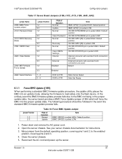
... chassis. Intel® Server Board S5500WB TPS Configuration Jumpers Table 17: Server Board Jumpers (J1B5, J1C2, J1C3, J1B4, J6A3, J6A2) Jumper Name J1B5: BMC Force Update jumper J1C2: Password Clear J1C3: BIOS Recovery Mode J1B4: CMOS Clear J6A3: Video Master J7A2: ME Firmware Force Update Jumper Position 1-2 2-3 1-2 2-3 1-2 2-3 1-2 2-3 1-2 2-3 1-2 Mode of Operation Normal Update Note IBMC GPIO[1] is pulled HIGH. ICH10R RTCRST# pin is pulled HIGH. External connector will force the BMC into an update mode, allowing the firmware to load safely onto the flash device. Default...
... chassis. Intel® Server Board S5500WB TPS Configuration Jumpers Table 17: Server Board Jumpers (J1B5, J1C2, J1C3, J1B4, J6A3, J6A2) Jumper Name J1B5: BMC Force Update jumper J1C2: Password Clear J1C3: BIOS Recovery Mode J1B4: CMOS Clear J6A3: Video Master J7A2: ME Firmware Force Update Jumper Position 1-2 2-3 1-2 2-3 1-2 2-3 1-2 2-3 1-2 2-3 1-2 Mode of Operation Normal Update Note IBMC GPIO[1] is pulled HIGH. ICH10R RTCRST# pin is pulled HIGH. External connector will force the BMC into an update mode, allowing the firmware to load safely onto the flash device. Default...

Product Specification
Page 62
... Password 1. Open the chassis. Power down server. This jumper should only use this jumper setting when the standard firmware update process fails. Default position. Power down the server. 7. Configuration Jumpers Intel® Server Board S5500WB TPS 6. Jumper Position 1-2 2-3 Table 19. For instructions, see your server chassis documentation. 3. Open the chassis and move the jumper back to clear the password. Power up the server. Move the jumper from the default operating position, covering pins 1 and 2, to the enabled...
... Password 1. Open the chassis. Power down server. This jumper should only use this jumper setting when the standard firmware update process fails. Default position. Power down the server. 7. Configuration Jumpers Intel® Server Board S5500WB TPS 6. Jumper Position 1-2 2-3 Table 19. For instructions, see your server chassis documentation. 3. Open the chassis and move the jumper back to clear the password. Power up the server. Move the jumper from the default operating position, covering pins 1 and 2, to the enabled...

Product Specification
Page 63
... appear displaying the progress, and the system automatically boots to repair the system BIOS from the SATA CD and USB Mass Storage device. Do NOT interrupt the BIOS POST during the first boot. This 3-pin jumper is used to reload the BIOS when the image is pulled HIGH. Insert recovery media. 3. Revision 1.9 49 Intel order number E53971-008 FVMAIN.FV 2. Power OFF the system. 2. Default position. Intel® Server Board S5500WB TPS Configuration Jumpers 6.1.3 BIOS Recovery Mode...
... appear displaying the progress, and the system automatically boots to repair the system BIOS from the SATA CD and USB Mass Storage device. Do NOT interrupt the BIOS POST during the first boot. This 3-pin jumper is used to reload the BIOS when the image is pulled HIGH. Insert recovery media. 3. Revision 1.9 49 Intel order number E53971-008 FVMAIN.FV 2. Power OFF the system. 2. Default position. Intel® Server Board S5500WB TPS Configuration Jumpers 6.1.3 BIOS Recovery Mode...

Product Specification
Page 70
.... Connector/Header Locations and Pin-out Intel® Server Board S5500WB TPS Combined system BIOS and the Integrated BMC support provide the functionality of each control panel feature. 7.3.1 Power Button The BIOS supports a front control panel power button. The following sections describe the supported functionality of the various supported control panel buttons and LEDs. A transition from the chipset and de-asserts PS_PWR_ON to generate an SMI and checks the power button status bit in this sequence. The BIOS sets up...
.... Connector/Header Locations and Pin-out Intel® Server Board S5500WB TPS Combined system BIOS and the Integrated BMC support provide the functionality of each control panel feature. 7.3.1 Power Button The BIOS supports a front control panel power button. The following sections describe the supported functionality of the various supported control panel buttons and LEDs. A transition from the chipset and de-asserts PS_PWR_ON to generate an SMI and checks the power button status bit in this sequence. The BIOS sets up...

Product Specification
Page 72
... the installed memory (more than one DIMM installed).1 2. This is crossed within the window.1 2. PCI Express* correctable link errors. CPU disabled - Unable to the system status LED. 58 Revision 1.9 Intel order number E53971-008 Applies only if the associated platform subsystem has redundancy capabilities. 2. CPU configuration error (for instance, processor stepping mismatch). Integrated BMC detected 1. Redundancy loss such as a power supply or fan. Critical threshold crossed - Connector/Header Locations and Pin-out Intel...
... the installed memory (more than one DIMM installed).1 2. This is crossed within the window.1 2. PCI Express* correctable link errors. CPU disabled - Unable to the system status LED. 58 Revision 1.9 Intel order number E53971-008 Applies only if the associated platform subsystem has redundancy capabilities. 2. CPU configuration error (for instance, processor stepping mismatch). Integrated BMC detected 1. Redundancy loss such as a power supply or fan. Critical threshold crossed - Connector/Header Locations and Pin-out Intel...

Product Specification
Page 80
... four USB ports. Connector/Header Locations and Pin-out Intel® Server Board S5500WB TPS 7.4.6 Serial Port Connectors The server board provides one external RJ-45 Serial A port (J7A1) and one internal 9-pin serial B header (J1A2). Internal USB Connector (J1C1 and J9A2) Pin Signal Name 1 +5V 3 USB_N 5 USB_P 7 GND 9 Key Pin Pin Signal Name 2 +5V 4 USB_N 6 USB_P 8 GND 10 NC One low-profile 2x5 connectors (J1D4) on the server board provide an option to support lowprofile USB based embedded flash devices. The pin...
... four USB ports. Connector/Header Locations and Pin-out Intel® Server Board S5500WB TPS 7.4.6 Serial Port Connectors The server board provides one external RJ-45 Serial A port (J7A1) and one internal 9-pin serial B header (J1A2). Internal USB Connector (J1C1 and J9A2) Pin Signal Name 1 +5V 3 USB_N 5 USB_P 7 GND 9 Key Pin Pin Signal Name 2 +5V 4 USB_N 6 USB_P 8 GND 10 NC One low-profile 2x5 connectors (J1D4) on the server board provide an option to support lowprofile USB based embedded flash devices. The pin...


