User Guide
Page 7
... and using the utilities that are responsible for troubleshooting, upgrading, and repairing this server board. Chapter 2 provides instructions on adding and replacing components. See "Additional Information and Software" for installing or replacing components such as the memory, processor, control panel board, and the battery, among other components you may be required to add and replace components on the Title of a problem. Use this chapter, you identify components and their locations. This manual...
... and using the utilities that are responsible for troubleshooting, upgrading, and repairing this server board. Chapter 2 provides instructions on adding and replacing components. See "Additional Information and Software" for installing or replacing components such as the memory, processor, control panel board, and the battery, among other components you may be required to add and replace components on the Title of a problem. Use this chapter, you identify components and their locations. This manual...
User Guide
Page 8
... Software For this information or software For in the table below, once on this server board, use the following accessory items for your board, and for ordering information for Intel products, see http://support.intel.com/support/motherboards/server/S5000VSA/ compat.htm. For information about this product or information about the accessories that can be used with your server: Processor, memory DIMMs, hard drive, CD-ROM or DVD-ROM drive, RAID controller...
... Software For this information or software For in the table below, once on this server board, use the following accessory items for your board, and for ordering information for Intel products, see http://support.intel.com/support/motherboards/server/S5000VSA/ compat.htm. For information about this product or information about the accessories that can be used with your server: Processor, memory DIMMs, hard drive, CD-ROM or DVD-ROM drive, RAID controller...
User Guide
Page 11
...1 RAID Support ...3 SATA Server Board ...3 SAS Server Board ...4 Connector and Component Locations 5 Configuration Jumpers ...7 Back Panel Connectors ...8 Hardware Requirements ...9 Processor ...9 Memory ...9 Power Supply ...9 Optional Hardware ...10 Hard Disk Drives ...10 Intel® Local Control Panel 10 Chapter 2: Server Utilities 11 Using the BIOS Setup Utility 11 Starting Setup ...11 If You Cannot Access Setup 11 Setup Menus ...11 Upgrading the BIOS ...13 Preparing for the Upgrade 13 Upgrading the BIOS ...14 Clearing the Password ...15 Chapter 3: Hardware Installations and Upgrades...
...1 RAID Support ...3 SATA Server Board ...3 SAS Server Board ...4 Connector and Component Locations 5 Configuration Jumpers ...7 Back Panel Connectors ...8 Hardware Requirements ...9 Processor ...9 Memory ...9 Power Supply ...9 Optional Hardware ...10 Hard Disk Drives ...10 Intel® Local Control Panel 10 Chapter 2: Server Utilities 11 Using the BIOS Setup Utility 11 Starting Setup ...11 If You Cannot Access Setup 11 Setup Menus ...11 Upgrading the BIOS ...13 Preparing for the Upgrade 13 Upgrading the BIOS ...14 Clearing the Password ...15 Chapter 3: Hardware Installations and Upgrades...

User Guide
Page 12
... Not Light 40 No Characters Appear on Screen 40 Characters Are Distorted or Incorrect 41 System Cooling Fans Do Not Rotate Properly 41 CD-ROM Drive or DVD-ROM Drive Activity Light Does Not Light 42 Cannot Connect to a Server 42 Problems with Network 42 System Boots when Installing PCI Card 43 Problems with Newly Installed Application Software 43 Problems with Application Software that Ran Correctly Earlier 44 xii Intel® Server Board S5000VSA User's Guide
... Not Light 40 No Characters Appear on Screen 40 Characters Are Distorted or Incorrect 41 System Cooling Fans Do Not Rotate Properly 41 CD-ROM Drive or DVD-ROM Drive Activity Light Does Not Light 42 Cannot Connect to a Server 42 Problems with Network 42 System Boots when Installing PCI Card 43 Problems with Newly Installed Application Software 43 Problems with Application Software that Ran Correctly Earlier 44 xii Intel® Server Board S5000VSA User's Guide
User Guide
Page 20
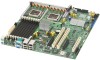
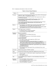
... generation Quad-Core Intel® Xeon® processors. Up to two 45nm 2P Dual-Core Intel® Xeon® processors. Optional RAID 5 support requires an AXXRAKSW5 RAID key. • Four SAS and two SATA connectors with embedded RAID 0/1/10 support for up to two drives • SATA support • SAS support (optional) Intel® 82563EB dual port controller for S5000VSASATA/S5000VSASATAR and S5000VSASCSI/S5000VSASCSIR SKUs. or 1333-MHz front side bus. Server Board Features Feature Processor Memory Chipset Peripheral Interfaces I/O Control Video Hard drive LAN Expansion...
... generation Quad-Core Intel® Xeon® processors. Up to two 45nm 2P Dual-Core Intel® Xeon® processors. Optional RAID 5 support requires an AXXRAKSW5 RAID key. • Four SAS and two SATA connectors with embedded RAID 0/1/10 support for up to two drives • SATA support • SAS support (optional) Intel® 82563EB dual port controller for S5000VSASATA/S5000VSASATAR and S5000VSASCSI/S5000VSASCSIR SKUs. or 1333-MHz front side bus. Server Board Features Feature Processor Memory Chipset Peripheral Interfaces I/O Control Video Hard drive LAN Expansion...
User Guide
Page 21
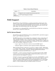
... a cable is attached between this activation key is selected, you can be set to configure RAID. To enable RAID 5, this connector on the Advanced | ATA Controller setup page, some of the server board. the SATA model provides only SATA support. Server Board Features Feature Description Fans System Management Support for RAID configurations. If RAID 5 is desired, the optional Intel® RAID Activation Key AXXRAKSW5 (available post-release) can choose to enable or disable "AHCI Mode" or "Configure SATA as follows: • Legacy supports four disk drives...
... a cable is attached between this activation key is selected, you can be set to configure RAID. To enable RAID 5, this connector on the Advanced | ATA Controller setup page, some of the server board. the SATA model provides only SATA support. Server Board Features Feature Description Fans System Management Support for RAID configurations. If RAID 5 is desired, the optional Intel® RAID Activation Key AXXRAKSW5 (available post-release) can choose to enable or disable "AHCI Mode" or "Configure SATA as follows: • Legacy supports four disk drives...
User Guide
Page 23
... Advanced | Mass Storage setup page to enable RAID 5, see the Intel® Server Board S5000VSA Technical Product Specification. Both SAS and SATA controllers support SGPIO enclosure management. Intel® Server Board S5000VSA User's Guide 5 When the SAS controller is disabled in the BIOS Setup utility, Intel® Embedded Server RAID Technology II is desired, the optional Intel® RAID Activation Key AXXRAKSW5 (available post-release) can mix SAS and SATA drives. Two SGPIO connectors are used as SATA ports. The SAS controller can be...
... Advanced | Mass Storage setup page to enable RAID 5, see the Intel® Server Board S5000VSA Technical Product Specification. Both SAS and SATA controllers support SGPIO enclosure management. Intel® Server Board S5000VSA User's Guide 5 When the SAS controller is disabled in the BIOS Setup utility, Intel® Embedded Server RAID Technology II is desired, the optional Intel® RAID Activation Key AXXRAKSW5 (available post-release) can mix SAS and SATA drives. Two SGPIO connectors are used as SATA ports. The SAS controller can be...
User Guide
Page 25
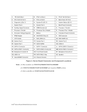
A. PCI-X 64/100 Slot 5 G. System Fan 6 M. IPMB Header Y. SATA 0 Connector KK. SATA 3/SAS 1 Connector NN. Serial B EMP Connector B. System ID LED (1) K. SAS RAID 5 Key (3) Z. System Fan 4 FF. Front Panel Header RR. Back Panel I/O Ports I. Processor Power Connector X. Backplane Connector A SS. Server Board Connector and Component Locations Notes: (1) Not available on S5000VSA4DIMM/S5000VSA4DIMMR. (2) S5000VSA4DIMM/S5000VSA4DIMMR only has four DIMM sockets. (3) Only available on S5000VSASAS/S5000VSASASR. Intel® Server Board S5000VSA User's Guide 7 Processor Voltage ...
A. PCI-X 64/100 Slot 5 G. System Fan 6 M. IPMB Header Y. SATA 0 Connector KK. SATA 3/SAS 1 Connector NN. Serial B EMP Connector B. System ID LED (1) K. SAS RAID 5 Key (3) Z. System Fan 4 FF. Front Panel Header RR. Back Panel I/O Ports I. Processor Power Connector X. Backplane Connector A SS. Server Board Connector and Component Locations Notes: (1) Not available on S5000VSA4DIMM/S5000VSA4DIMMR. (2) S5000VSA4DIMM/S5000VSA4DIMMR only has four DIMM sockets. (3) Only available on S5000VSASAS/S5000VSASASR. Intel® Server Board S5000VSA User's Guide 7 Processor Voltage ...
User Guide
Page 28
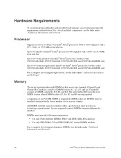
... installed starting with the lowest number slot in DIMM socket A1. Product codes S5000VSASATAR, S5000VSASASR, S5000VSASCSIR, and S5000VSA4DIMMR only. Channel B consists of DIMM sockets A1, A2, A3, and A4. Up to two 45nm 2P Dual-Core Intel® Xeon® processors. Memory The server board provides eight DIMM sockets across two channels, Channel A and Channel B. A minimum of supported memory DIMMs, see the links under "Additional Information and Software." Channel A consists of DIMM sockets...
... installed starting with the lowest number slot in DIMM socket A1. Product codes S5000VSASATAR, S5000VSASASR, S5000VSASCSIR, and S5000VSA4DIMMR only. Channel B consists of DIMM sockets A1, A2, A3, and A4. Up to two 45nm 2P Dual-Core Intel® Xeon® processors. Memory The server board provides eight DIMM sockets across two channels, Channel A and Channel B. A minimum of supported memory DIMMs, see the links under "Additional Information and Software." Channel A consists of DIMM sockets...

User Guide
Page 29
... server chassis for additional drive information and drive installation instructions. The IDE connection supports one or two ATA-133 devices. IDE devices can be connected to the standard IDE connector located near the front left side of the server board. The IDE connection supports one or two ATA-133 devices. Power Supply A minimum of the server board purchased. • The Intel® Server Board S5000VSASATA/S5000VSASATAR provides six SATA ports and one IDE connection. Optional Hardware Hard Disk Drives The server board supports different hard disk drive options, depending...
... server chassis for additional drive information and drive installation instructions. The IDE connection supports one or two ATA-133 devices. IDE devices can be connected to the standard IDE connector located near the front left side of the server board. The IDE connection supports one or two ATA-133 devices. Power Supply A minimum of the server board purchased. • The Intel® Server Board S5000VSASATA/S5000VSASATAR provides six SATA ports and one IDE connection. Optional Hardware Hard Disk Drives The server board supports different hard disk drive options, depending...

User Guide
Page 31
... you have moved the CMOS jumper on the server board to clear the CMOS memory. Setup Menus Each BIOS Setup menu page contains a number of features. You can enter and start BIOS Setup under several conditions: • When you turn on clearing the CMOS, see this condition, the BIOS will find details about specific BIOS setup screens. For instructions on the server, after POST completes the memory test. • When you will load default values for any...
... you have moved the CMOS jumper on the server board to clear the CMOS memory. Setup Menus Each BIOS Setup menu page contains a number of features. You can enter and start BIOS Setup under several conditions: • When you turn on clearing the CMOS, see this condition, the BIOS will find details about specific BIOS setup screens. For instructions on the server, after POST completes the memory test. • When you will load default values for any...
User Guide
Page 43
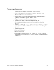
... CPU load plate. 11. "Intel® Server Board S5000VSA User's Guide" 25 Turn off all peripheral devices connected to break the seal between the heat sink and the processor. 8. Removing a Processor 1. Loosen the four captive screws on removing the server's cover. 5. Do not force the heat sink from the server board. 6. Turn off the server. 3. Otherwise, install the protective socket cover over the empty processor socket and reinstall the chassis...
... CPU load plate. 11. "Intel® Server Board S5000VSA User's Guide" 25 Turn off all peripheral devices connected to break the seal between the heat sink and the processor. 8. Removing a Processor 1. Loosen the four captive screws on removing the server's cover. 5. Do not force the heat sink from the server board. 6. Turn off the server. 3. Otherwise, install the protective socket cover over the empty processor socket and reinstall the chassis...
User Guide
Page 59
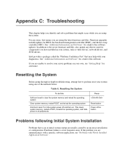
... as video drivers, network drivers, and SCSI drivers. Appendix C: Troubleshooting This chapter helps you identify and solve problems that may help with Newly Installed Application Software". For any drivers used for BIOS, the baseboard management controller (BMC), and the hot-swap controller (HSC). Turn the system power off /on . This clears system memory, restarts POST, reloads the operating system, and halts power to all peripherals Press Reset button Power off and then on button Problems...
... as video drivers, network drivers, and SCSI drivers. Appendix C: Troubleshooting This chapter helps you identify and solve problems that may help with Newly Installed Application Software". For any drivers used for BIOS, the baseboard management controller (BMC), and the hot-swap controller (HSC). Turn the system power off /on . This clears system memory, restarts POST, reloads the operating system, and halts power to all peripherals Press Reset button Power off and then on button Problems...

User Guide
Page 60
... all device drivers properly installed? • Are the configuration settings made in Setup correct? • Is the operating system properly loaded? Caution: Turn off devices before disconnecting cables: Before disconnecting any peripheral cables from the tested components lists? If applicable, ensure that comes with them. Check the tested memory, and chassis lists, as well as the supported hardware and operating system list. Turn off switch on the front panel to turn...
... all device drivers properly installed? • Are the configuration settings made in Setup correct? • Is the operating system properly loaded? Caution: Turn off devices before disconnecting cables: Before disconnecting any peripheral cables from the tested components lists? If applicable, ensure that comes with them. Check the tested memory, and chassis lists, as well as the supported hardware and operating system list. Turn off switch on the front panel to turn...
User Guide
Page 62
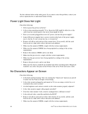
... according to the system requirements. • Remove the memory DIMMs and re-seat them . • Make sure the chassis standoffs are using a switch box, is functioning. • Is the video monitor plugged in and turned on the video monitor properly adjusted? • Is the video monitor signal cable properly installed? • Does this video monitor work correctly if plugged into the power supply? • Some ATX power supplies have been populated according to the...
... according to the system requirements. • Remove the memory DIMMs and re-seat them . • Make sure the chassis standoffs are using a switch box, is functioning. • Is the video monitor plugged in and turned on the video monitor properly adjusted? • Is the video monitor signal cable properly installed? • Does this video monitor work correctly if plugged into the power supply? • Some ATX power supplies have been populated according to the...

User Guide
Page 63
... in the server board connector. 3. Intel® Server Board S5000VSA User's Guide 45 If there are using the onboard video controller. 2. This information is an indication of the fan motors stopped? Use the server management subsystem to check the fan status. • Have your fans speeded up in response to an overheating situation? • Have your fans speeded up in video controller board, do not appear, the video display monitor or video controller may have...
... in the server board connector. 3. Intel® Server Board S5000VSA User's Guide 45 If there are using the onboard video controller. 2. This information is an indication of the fan motors stopped? Use the server management subsystem to check the fan status. • Have your fans speeded up in response to an overheating situation? • Have your fans speeded up in video controller board, do not appear, the video display monitor or video controller may have...

User Guide
Page 64
... hub port is configured for information on the drive set correctly? • Is the drive properly configured? For these drivers, it may require interrupts that are not shared with your PCI card(s) for the same duplex mode as the network controller. • Make sure the correct networking software is securely attached to the server board? • Are there any shorted wires caused by pinched-cables or have power connector plugs been...
... hub port is configured for information on the drive set correctly? • Is the drive properly configured? For these drivers, it may require interrupts that are not shared with your PCI card(s) for the same duplex mode as the network controller. • Make sure the correct networking software is securely attached to the server board? • Are there any shorted wires caused by pinched-cables or have power connector plugs been...

User Guide
Page 65
... AC power cord(s) from the onboard network controller. • Make sure your BIOS is properly installed and configured for the system. System Boots when Installing PCI Card System Server Management features require full-time "standby" power. See the software documentation. • Make sure the software is current. The add-in adapter stopped working when an add-in adapter was installed. • Make sure the cable is connected to...
... AC power cord(s) from the onboard network controller. • Make sure your BIOS is properly installed and configured for the system. System Boots when Installing PCI Card System Server Management features require full-time "standby" power. See the software documentation. • Make sure the software is current. The add-in adapter stopped working when an add-in adapter was installed. • Make sure the cable is connected to...
User Guide
Page 66
... a loose cable, dirt in BIOS Setup. • Make sure the drive is plugged into the power supply. 48 Intel® Server Board S5000VSA User's Guide • Use only an authorized copy. Problems with Application Software that Ran Correctly Earlier Problems that is connected correctly and that occur after the system hardware and software have occurred, reload the software and try a different disk. • Make sure the correct device drivers installed. See "Additional...
... a loose cable, dirt in BIOS Setup. • Make sure the drive is plugged into the power supply. 48 Intel® Server Board S5000VSA User's Guide • Use only an authorized copy. Problems with Application Software that Ran Correctly Earlier Problems that is connected correctly and that occur after the system hardware and software have occurred, reload the software and try a different disk. • Make sure the correct device drivers installed. See "Additional...

User Guide
Page 67
... condition Amber blinking = non-critical error Amber = critical or nonrecoverable error Intel® Server Board S5000VSA User's Guide 49 LED Information The Intel® Server Board S5000VSA includes LEDs that the master/slave settings are set correctly. A table of their use Server Management software to turn the LED on and off or in sleep state S5 On = Power is on or off Location Front control panel LED Color Green ID Aid in...
... condition Amber blinking = non-critical error Amber = critical or nonrecoverable error Intel® Server Board S5000VSA User's Guide 49 LED Information The Intel® Server Board S5000VSA includes LEDs that the master/slave settings are set correctly. A table of their use Server Management software to turn the LED on and off or in sleep state S5 On = Power is on or off Location Front control panel LED Color Green ID Aid in...


