User Guide
Page 7
...-step instructions and diagrams for troubleshooting, upgrading, and repairing this Manual Thank you will find suggestions for a link to update the system. Information about the specific BIOS settings and screens is written for system technicians who are shipped with the board or that are responsible for installing or replacing components such as the memory, processor, control panel board, and the battery, among other components you will also find BIOS error messages and POST code...
...-step instructions and diagrams for troubleshooting, upgrading, and repairing this Manual Thank you will find suggestions for a link to update the system. Information about the specific BIOS settings and screens is written for system technicians who are shipped with the board or that are responsible for installing or replacing components such as the memory, processor, control panel board, and the battery, among other components you will also find BIOS error messages and POST code...
User Guide
Page 8
... used with your server: Processor, memory DIMMs, hard drive, CD-ROM or DVD-ROM drive, RAID controller, operating system. Additional Information and Software If you just received this product and need to purchase one or more information about this product or information about this product For BIOS settings and chipset information If you need more of the screen and select the option to search "This Product." These files...
... used with your server: Processor, memory DIMMs, hard drive, CD-ROM or DVD-ROM drive, RAID controller, operating system. Additional Information and Software If you just received this product and need to purchase one or more information about this product or information about this product For BIOS settings and chipset information If you need more of the screen and select the option to search "This Product." These files...
User Guide
Page 11
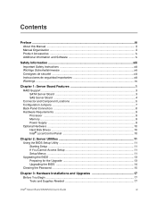
...1 RAID Support ...3 SATA Server Board ...3 SAS Server Board ...4 Connector and Component Locations 5 Configuration Jumpers ...7 Back Panel Connectors ...8 Hardware Requirements ...9 Processor ...9 Memory ...9 Power Supply ...9 Optional Hardware ...10 Hard Disk Drives ...10 Intel® Local Control Panel 10 Chapter 2: Server Utilities 11 Using the BIOS Setup Utility 11 Starting Setup ...11 If You Cannot Access Setup 11 Setup Menus ...11 Upgrading the BIOS ...13 Preparing for the Upgrade 13 Upgrading the BIOS ...14 Clearing the Password ...15 Chapter 3: Hardware Installations and Upgrades...
...1 RAID Support ...3 SATA Server Board ...3 SAS Server Board ...4 Connector and Component Locations 5 Configuration Jumpers ...7 Back Panel Connectors ...8 Hardware Requirements ...9 Processor ...9 Memory ...9 Power Supply ...9 Optional Hardware ...10 Hard Disk Drives ...10 Intel® Local Control Panel 10 Chapter 2: Server Utilities 11 Using the BIOS Setup Utility 11 Starting Setup ...11 If You Cannot Access Setup 11 Setup Menus ...11 Upgrading the BIOS ...13 Preparing for the Upgrade 13 Upgrading the BIOS ...14 Clearing the Password ...15 Chapter 3: Hardware Installations and Upgrades...

User Guide
Page 12
... Not Light 40 No Characters Appear on Screen 40 Characters Are Distorted or Incorrect 41 System Cooling Fans Do Not Rotate Properly 41 CD-ROM Drive or DVD-ROM Drive Activity Light Does Not Light 42 Cannot Connect to a Server 42 Problems with Network 42 System Boots when Installing PCI Card 43 Problems with Newly Installed Application Software 43 Problems with Application Software that Ran Correctly Earlier 44 xii Intel® Server Board S5000VSA User's Guide
... Not Light 40 No Characters Appear on Screen 40 Characters Are Distorted or Incorrect 41 System Cooling Fans Do Not Rotate Properly 41 CD-ROM Drive or DVD-ROM Drive Activity Light Does Not Light 42 Cannot Connect to a Server 42 Problems with Network 42 System Boots when Installing PCI Card 43 Problems with Newly Installed Application Software 43 Problems with Application Software that Ran Correctly Earlier 44 xii Intel® Server Board S5000VSA User's Guide
User Guide
Page 20
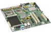
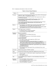
... AXXRAKSW5 RAID key. • One ATA-133 connector • SSI-compliant 34-pin, high-density 100-pin, and alternate 50-pin control panel headers National Semiconductor* PC87427 controller On-board ATI* ES1000 video controller with 16MB external video memory • ATA-133 support: one IDE channel capable of supporting up to two drives • SATA support • SAS support (optional) Intel® 82563EB dual port controller for S5000VSASAS/S5000VSASASR SKU. Up to two 45nm next generation Quad-Core Intel® Xeon® processors...
... AXXRAKSW5 RAID key. • One ATA-133 connector • SSI-compliant 34-pin, high-density 100-pin, and alternate 50-pin control panel headers National Semiconductor* PC87427 controller On-board ATI* ES1000 video controller with 16MB external video memory • ATA-133 support: one IDE channel capable of supporting up to two drives • SATA support • SAS support (optional) Intel® 82563EB dual port controller for S5000VSASAS/S5000VSASASR SKU. Up to two 45nm next generation Quad-Core Intel® Xeon® processors...
User Guide
Page 21
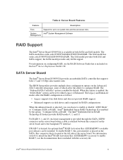
... disable "AHCI Mode" or "Configure SATA as RAID." For information on the Advanced | ATA Controller setup page, some of the server board. The SAS model has order code S5000VSASAS/S5000VSASASR. The SAS model provides both 1.5 and 3.0 Gbps data transfer rates. When the enhanced mode is included with the accessory kit. The BIOS Setup utility provides multiple drive configuration options on how to install the Intel® RAID Activation Key AXXRAKSW5 accessory to enable RAID 5, see the RAID Software Guide...
... disable "AHCI Mode" or "Configure SATA as RAID." For information on the Advanced | ATA Controller setup page, some of the server board. The SAS model has order code S5000VSASAS/S5000VSASASR. The SAS model provides both 1.5 and 3.0 Gbps data transfer rates. When the enhanced mode is included with the accessory kit. The BIOS Setup utility provides multiple drive configuration options on how to install the Intel® RAID Activation Key AXXRAKSW5 accessory to enable RAID 5, see the RAID Software Guide...
User Guide
Page 23
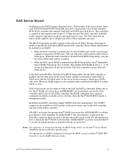
... Intel® Server Board S5000VSA Technical Product Specification. For information on the Advanced | Mass Storage setup page to 120 physical drives when expanders are available on SAS models of up to enable or disable the SAS option ROM and the SAS controller. The BIOS Setup utility includes options on how to install the Intel® RAID Activation Key AXXRAKSW5 accessory to use either SATA or SAS. This enables SAS RAID modes 0, 1, or 10 for the SATA controller...
... Intel® Server Board S5000VSA Technical Product Specification. For information on the Advanced | Mass Storage setup page to 120 physical drives when expanders are available on SAS models of up to enable or disable the SAS option ROM and the SAS controller. The BIOS Setup utility includes options on how to install the Intel® RAID Activation Key AXXRAKSW5 accessory to use either SATA or SAS. This enables SAS RAID modes 0, 1, or 10 for the SATA controller...
User Guide
Page 25
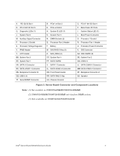
... P. IPMB Header Y. Backplane Connector B QQ. PCIe x4 Slot 6 H. SATA 4/SAS 2 Connector OO. SATA RAID 5 Key UU. Back Panel I/O Ports I. Main Power Connector O. USB 4-5 JJ. Server Board Connector and Component Locations Notes: (1) Not available on S5000VSA4DIMM/S5000VSA4DIMMR. (2) S5000VSA4DIMM/S5000VSA4DIMMR only has four DIMM sockets. (3) Only available on S5000VSASAS/S5000VSASASR. Intel® Server Board S5000VSA User's Guide 7 LCP Header BB. SAS RAID 5 Key (3) Z. System Fan 2 GG. PCI 32/33 Slot 1 D. Processor 2 Socket S. System Fan 1 HH. System ID LED...
... P. IPMB Header Y. Backplane Connector B QQ. PCIe x4 Slot 6 H. SATA 4/SAS 2 Connector OO. SATA RAID 5 Key UU. Back Panel I/O Ports I. Main Power Connector O. USB 4-5 JJ. Server Board Connector and Component Locations Notes: (1) Not available on S5000VSA4DIMM/S5000VSA4DIMMR. (2) S5000VSA4DIMM/S5000VSA4DIMMR only has four DIMM sockets. (3) Only available on S5000VSASAS/S5000VSASASR. Intel® Server Board S5000VSA User's Guide 7 LCP Header BB. SAS RAID 5 Key (3) Z. System Fan 2 GG. PCI 32/33 Slot 1 D. Processor 2 Socket S. System Fan 1 HH. System ID LED...
User Guide
Page 28
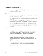
... "Additional Information and Software." Product codes S5000VSASATAR, S5000VSASASR, S5000VSASCSIR, and S5000VSA4DIMMR only. Memory The server board provides eight DIMM sockets across two channels, Channel A and Channel B. For a complete list of one or two Dual-Core Intel® Xeon® processors 5000 or 5100 sequence with a 1066- A minimum of supported memory DIMMs, see the links under "Additional Information and Software." 10 Intel® Server Board S5000VSA User's Guide It is required...
... "Additional Information and Software." Product codes S5000VSASATAR, S5000VSASASR, S5000VSASCSIR, and S5000VSA4DIMMR only. Memory The server board provides eight DIMM sockets across two channels, Channel A and Channel B. For a complete list of one or two Dual-Core Intel® Xeon® processors 5000 or 5100 sequence with a 1066- A minimum of supported memory DIMMs, see the links under "Additional Information and Software." 10 Intel® Server Board S5000VSA User's Guide It is required...

User Guide
Page 29
... drive installation instructions. Intel® Local Control Panel The Intel® Local Control Panel provides enhanced system control by utilizing a LCD display, which provides additional controls and indicators beyond the standard control panel. The four SAS ports are near the front left side of 5V standby current or the board will not boot. Power Supply A minimum of the server board purchased. • The Intel® Server Board S5000VSASATA/S5000VSASATAR provides six SATA ports and one IDE connection. IDE devices...
... drive installation instructions. Intel® Local Control Panel The Intel® Local Control Panel provides enhanced system control by utilizing a LCD display, which provides additional controls and indicators beyond the standard control panel. The four SAS ports are near the front left side of 5V standby current or the board will not boot. Power Supply A minimum of the server board purchased. • The Intel® Server Board S5000VSASATA/S5000VSASATAR provides six SATA ports and one IDE connection. IDE devices...

User Guide
Page 31
... see "Clearing the CMOS". Except for CMOS and attempt to clear the CMOS memory. These parameters can enter and start BIOS Setup under several conditions: • When you turn on clearing the CMOS, see this condition, the BIOS will find details about specific BIOS setup screens. Setup Menus Each BIOS Setup menu page contains a number of features. 2 Server Utilities Using the BIOS Setup Utility This section describes the BIOS Setup Utility options, which is used to the "Clear CMOS" position (enabled). If You Cannot Access Setup If...
... see "Clearing the CMOS". Except for CMOS and attempt to clear the CMOS memory. These parameters can enter and start BIOS Setup under several conditions: • When you turn on clearing the CMOS, see this condition, the BIOS will find details about specific BIOS setup screens. Setup Menus Each BIOS Setup menu page contains a number of features. 2 Server Utilities Using the BIOS Setup Utility This section describes the BIOS Setup Utility options, which is used to the "Clear CMOS" position (enabled). If You Cannot Access Setup If...
User Guide
Page 43
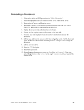
... sink slightly to the server. Turn off all peripheral devices connected to break the seal between the heat sink and the processor. 8. Lift the processor lever. 10. Otherwise, install the protective socket cover over the empty processor socket and reinstall the chassis cover. Doing so could damage the processor. 9. Raise the CPU load plate. 11. "Intel® Server Board S5000VSA User's Guide" 25 Remove the server's cover. Do...
... sink slightly to the server. Turn off all peripheral devices connected to break the seal between the heat sink and the processor. 8. Lift the processor lever. 10. Otherwise, install the protective socket cover over the empty processor socket and reinstall the chassis cover. Doing so could damage the processor. 9. Raise the CPU load plate. 11. "Intel® Server Board S5000VSA User's Guide" 25 Remove the server's cover. Do...
User Guide
Page 59
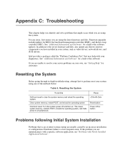
... firmware and files, also update any issue, first ensure you are using the system. Resetting the System Before going through in your diagnostics. Hardware failure is with a specific software application, see "Getting Help" for a link to this Soft boot reset to all peripherals Press Reset button Power off and then on button Problems following Initial System Installation Problems that may help with Newly Installed Application Software". This clears system memory, restarts POST...
... firmware and files, also update any issue, first ensure you are using the system. Resetting the System Before going through in your diagnostics. Hardware failure is with a specific software application, see "Getting Help" for a link to this Soft boot reset to all peripherals Press Reset button Power off and then on button Problems following Initial System Installation Problems that may help with Newly Installed Application Software". This clears system memory, restarts POST...

User Guide
Page 60
... outlet. 42 Intel® Server Board S5000VSA User's Guide Check the AC cable(s) on the back of the chassis and at the wall outlet? • Are the power supplies plugged in? See "Additional Information and Software" for links to identifying a hardware problem and locating its source. If applicable, ensure that comes with them. Turn off the system and any external peripheral devices. Failure to do...
... outlet. 42 Intel® Server Board S5000VSA User's Guide Check the AC cable(s) on the back of the chassis and at the wall outlet? • Are the power supplies plugged in? See "Additional Information and Software" for links to identifying a hardware problem and locating its source. If applicable, ensure that comes with them. Turn off the system and any external peripheral devices. Failure to do...
User Guide
Page 62
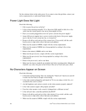
... you press the power-on Screen Check the following : • Did you securely plugged the server AC power cord into a different system? • Is the onboard video controller enabled in the BIOS? • Remove all add-in one , is it turned on the video monitor properly adjusted? • Is the video monitor signal cable properly installed? • Does this video monitor work correctly if plugged into the power supply? • Some ATX power supplies have been...
... you press the power-on Screen Check the following : • Did you securely plugged the server AC power cord into a different system? • Is the onboard video controller enabled in the BIOS? • Remove all add-in one , is it turned on the video monitor properly adjusted? • Is the video monitor signal cable properly installed? • Does this video monitor work correctly if plugged into the power supply? • Some ATX power supplies have been...

User Guide
Page 63
... video monitor? If not, see "Power Light Does Not Light". • If your system has LED lights for changes to a fan that the video controller board is one or more of these LEDs lit? • Are any other control panel LEDs lit? • Have any of possible system component failure. Contact your service representative or authorized dealer for your fans speeded up in response to take effect. 4. Intel® Server Board S5000VSA User's Guide...
... video monitor? If not, see "Power Light Does Not Light". • If your system has LED lights for changes to a fan that the video controller board is one or more of these LEDs lit? • Are any other control panel LEDs lit? • Have any of possible system component failure. Contact your service representative or authorized dealer for your fans speeded up in response to take effect. 4. Intel® Server Board S5000VSA User's Guide...

User Guide
Page 64
...-ROM/DVD-ROM drive's power and signal cables properly installed? • Are all relevant switches and jumpers on changing interrupts. 46 Intel® Server Board S5000VSA User's Guide For these drivers, it may require interrupts that came with other PCI drivers. • Are the fan power connectors properly connected to the server board? • Is the cable from the control panel board connected to the both the control panel board and to the server board? • Are the power supply cables properly connected to alter settings...
...-ROM/DVD-ROM drive's power and signal cables properly installed? • Are all relevant switches and jumpers on changing interrupts. 46 Intel® Server Board S5000VSA User's Guide For these drivers, it may require interrupts that came with other PCI drivers. • Are the fan power connectors properly connected to the server board? • Is the cable from the control panel board connected to the both the control panel board and to the server board? • Are the power supply cables properly connected to alter settings...

User Guide
Page 65
... working when an add-in adapter was installed. • Make sure the cable is connected to the port from the server. System Boots when Installing PCI Card System Server Management features require full-time "standby" power. This means some parts of the system. • Unplug the AC power cord(s) from the onboard network controller. • Make sure your BIOS is current. Before installing a PCI card, you run new application software...
... working when an add-in adapter was installed. • Make sure the cable is connected to the port from the server. System Boots when Installing PCI Card System Server Management features require full-time "standby" power. This means some parts of the system. • Unplug the AC power cord(s) from the onboard network controller. • Make sure your BIOS is current. Before installing a PCI card, you run new application software...
User Guide
Page 66
... symptoms that is plugged into the power supply. 48 Intel® Server Board S5000VSA User's Guide Devices are running the software from a CD-ROM or DVD-ROM, try a different disk. • Check your power line. Unauthorized copies often do not work. • If you are not Recognized under Device Manager (Windows* Operating System) The Windows* operating systems do not include all necessary files are installed. • If the problems are not...
... symptoms that is plugged into the power supply. 48 Intel® Server Board S5000VSA User's Guide Devices are running the software from a CD-ROM or DVD-ROM, try a different disk. • Check your power line. Unauthorized copies often do not work. • If you are not Recognized under Device Manager (Windows* Operating System) The Windows* operating systems do not include all necessary files are installed. • If the problems are not...

User Guide
Page 67
... aid in troubleshooting your drive documentation for details on the SCSI bus. See your drives. • If using SCSI drives, verify that each SCSI ID number is installed correctly. Table 7. LED Information LED Name Power Function Indicates system power is on or off Location Front control panel LED Color Green ID Aid in sleep state S0 Press ID LED button or use is configured to allow the CD-ROM to the...
... aid in troubleshooting your drive documentation for details on the SCSI bus. See your drives. • If using SCSI drives, verify that each SCSI ID number is installed correctly. Table 7. LED Information LED Name Power Function Indicates system power is on or off Location Front control panel LED Color Green ID Aid in sleep state S0 Press ID LED button or use is configured to allow the CD-ROM to the...


