User Guide
Page 7
...-step instructions and diagrams for purchasing and using the utilities that are responsible for troubleshooting, upgrading, and repairing this Manual Thank you will also find a list of the server board features, photos of a problem. Use this manual, see http://support.intel.com/ support/motherboards/server/S5000VSA/. In this chapter, you will find BIOS error messages and POST code messages. Chapter 2 provides instructions on using the Intel® Server Board S5000VSA. Information about the specific BIOS settings and screens is...
...-step instructions and diagrams for purchasing and using the utilities that are responsible for troubleshooting, upgrading, and repairing this Manual Thank you will also find a list of the server board features, photos of a problem. Use this manual, see http://support.intel.com/ support/motherboards/server/S5000VSA/. In this chapter, you will find BIOS error messages and POST code messages. Chapter 2 provides instructions on using the Intel® Server Board S5000VSA. Information about the specific BIOS settings and screens is...
User Guide
Page 8
... received this product and need to install it For virtual system tours and interactive repair information Accessories or other Intel server products Use this Document or Software Intel® Server Board S5000VSA Technical Product Specification Intel® S5000 Server Board Family Data Sheet Intel® Server Board S5000VSA Quick Start User's Guide in -depth technical information about this product For BIOS settings and chipset information If you need or...
... received this product and need to install it For virtual system tours and interactive repair information Accessories or other Intel server products Use this Document or Software Intel® Server Board S5000VSA Technical Product Specification Intel® S5000 Server Board Family Data Sheet Intel® Server Board S5000VSA Quick Start User's Guide in -depth technical information about this product For BIOS settings and chipset information If you need or...
User Guide
Page 11
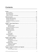
...1 RAID Support ...3 SATA Server Board ...3 SAS Server Board ...4 Connector and Component Locations 5 Configuration Jumpers ...7 Back Panel Connectors ...8 Hardware Requirements ...9 Processor ...9 Memory ...9 Power Supply ...9 Optional Hardware ...10 Hard Disk Drives ...10 Intel® Local Control Panel 10 Chapter 2: Server Utilities 11 Using the BIOS Setup Utility 11 Starting Setup ...11 If You Cannot Access Setup 11 Setup Menus ...11 Upgrading the BIOS ...13 Preparing for the Upgrade 13 Upgrading the BIOS ...14 Clearing the Password ...15 Chapter 3: Hardware Installations and Upgrades...
...1 RAID Support ...3 SATA Server Board ...3 SAS Server Board ...4 Connector and Component Locations 5 Configuration Jumpers ...7 Back Panel Connectors ...8 Hardware Requirements ...9 Processor ...9 Memory ...9 Power Supply ...9 Optional Hardware ...10 Hard Disk Drives ...10 Intel® Local Control Panel 10 Chapter 2: Server Utilities 11 Using the BIOS Setup Utility 11 Starting Setup ...11 If You Cannot Access Setup 11 Setup Menus ...11 Upgrading the BIOS ...13 Preparing for the Upgrade 13 Upgrading the BIOS ...14 Clearing the Password ...15 Chapter 3: Hardware Installations and Upgrades...

User Guide
Page 12
... Not Light 40 No Characters Appear on Screen 40 Characters Are Distorted or Incorrect 41 System Cooling Fans Do Not Rotate Properly 41 CD-ROM Drive or DVD-ROM Drive Activity Light Does Not Light 42 Cannot Connect to a Server 42 Problems with Network 42 System Boots when Installing PCI Card 43 Problems with Newly Installed Application Software 43 Problems with Application Software that Ran Correctly Earlier 44 xii Intel® Server Board S5000VSA User's Guide
... Not Light 40 No Characters Appear on Screen 40 Characters Are Distorted or Incorrect 41 System Cooling Fans Do Not Rotate Properly 41 CD-ROM Drive or DVD-ROM Drive Activity Light Does Not Light 42 Cannot Connect to a Server 42 Problems with Network 42 System Boots when Installing PCI Card 43 Problems with Newly Installed Application Software 43 Problems with Application Software that Ran Correctly Earlier 44 xii Intel® Server Board S5000VSA User's Guide
User Guide
Page 20
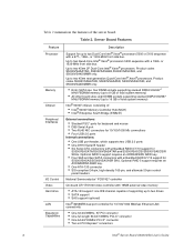
...-bit/133MHz PCI-X* connector • One 64-bit/100MHz PCI-X* connector • Two x4 PCI Express* connectors 2 Intel® Server Board S5000VSA User's Guide Optional RAID 5 support requires an AXXRAKSW5 RAID key. • Four SAS and two SATA connectors with embedded RAID 0/1/10 support for up to two Quad-Core Intel® Xeon® processors 5300 sequence with a 1066- Optional RAID 5 support requires an AXXRAKSW5 RAID key. • One ATA-133 connector • SSI-compliant 34-pin, high-density 100-pin, and alternate 50-pin control panel headers...
...-bit/133MHz PCI-X* connector • One 64-bit/100MHz PCI-X* connector • Two x4 PCI Express* connectors 2 Intel® Server Board S5000VSA User's Guide Optional RAID 5 support requires an AXXRAKSW5 RAID key. • Four SAS and two SATA connectors with embedded RAID 0/1/10 support for up to two Quad-Core Intel® Xeon® processors 5300 sequence with a 1066- Optional RAID 5 support requires an AXXRAKSW5 RAID key. • One ATA-133 connector • SSI-compliant 34-pin, high-density 100-pin, and alternate 50-pin control panel headers...
User Guide
Page 21
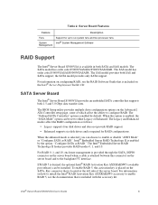
... server board when a cable is enabled by default. The BIOS Setup utility provides multiple drive configuration options on the SATA_Key connector that is desired, the optional Intel® RAID Activation Key AXXRAKSW5 (available post-release) can be installed. The "Onboard SATA Controller" option is included with the accessory kit. When this activation key is placed on the Advanced | ATA Controller setup page, some of the server board. The Legacy and Enhanced modes affect the RAID configuration as RAID." To enable RAID 5, this option...
... server board when a cable is enabled by default. The BIOS Setup utility provides multiple drive configuration options on the SATA_Key connector that is desired, the optional Intel® RAID Activation Key AXXRAKSW5 (available post-release) can be installed. The "Onboard SATA Controller" option is included with the accessory kit. When this activation key is placed on the Advanced | ATA Controller setup page, some of the server board. The Legacy and Enhanced modes affect the RAID configuration as RAID." To enable RAID 5, this option...
User Guide
Page 23
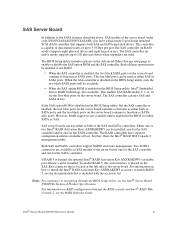
... board, one for the SAS controller and one for the SATA controller. The BIOS Setup utility includes options on RAID configuration through the BIOS Setup utility, see the RAID Software Guide. When the SAS controller is available. If the SAS option ROM is desired, the optional Intel® RAID Activation Key AXXRAKSW5 (available post-release) can be installed, one for the SAS controller and/or one for the SATA controller. If RAID 5 is disabled in the BIOS Setup utility, only the two black SATA ports...
... board, one for the SAS controller and one for the SATA controller. The BIOS Setup utility includes options on RAID configuration through the BIOS Setup utility, see the RAID Software Guide. When the SAS controller is available. If the SAS option ROM is desired, the optional Intel® RAID Activation Key AXXRAKSW5 (available post-release) can be installed, one for the SAS controller and/or one for the SATA controller. If RAID 5 is disabled in the BIOS Setup utility, only the two black SATA ports...
User Guide
Page 25
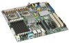
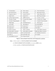
... IDE Connector AA. Server Board Connector and Component Locations Notes: (1) Not available on S5000VSA4DIMM/S5000VSA4DIMMR. (2) S5000VSA4DIMM/S5000VSA4DIMMR only has four DIMM sockets. (3) Only available on S5000VSASAS/S5000VSASASR. Intel® Server Board S5000VSA User's Guide 7 IPMB Header Y. SATA 0 Connector KK. Backplane Connector B QQ. Processor Fan 2 Header T. Back Panel I/O Ports I. Processor Fan 1 Header U. SATA 2/SAS 0 Connector MM. System Fan 6 M. Battery W. System Fan 4 FF. SATA RAID 5 Key UU. A. PCI 32/33 Slot 1 D. PCI-X 64/100 Slot 5 G. Diagnostic LEDs...
... IDE Connector AA. Server Board Connector and Component Locations Notes: (1) Not available on S5000VSA4DIMM/S5000VSA4DIMMR. (2) S5000VSA4DIMM/S5000VSA4DIMMR only has four DIMM sockets. (3) Only available on S5000VSASAS/S5000VSASASR. Intel® Server Board S5000VSA User's Guide 7 IPMB Header Y. SATA 0 Connector KK. Backplane Connector B QQ. Processor Fan 2 Header T. Back Panel I/O Ports I. Processor Fan 1 Header U. SATA 2/SAS 0 Connector MM. System Fan 6 M. Battery W. System Fan 4 FF. SATA RAID 5 Key UU. A. PCI 32/33 Slot 1 D. PCI-X 64/100 Slot 5 G. Diagnostic LEDs...
User Guide
Page 28
... 1333-MHz front side bus. Up to two 45nm next generation Quad-Core Intel® Xeon® processors. For a complete list of supported memory DIMMs, see the links under "Additional Information and Software." Memory The server board provides eight DIMM sockets across two channels, Channel A and Channel B. DIMMs must be installed starting with a 1066- DIMMs must meet the requirements outlined below. Processor Support for one 512 MB DIMM...
... 1333-MHz front side bus. Up to two 45nm next generation Quad-Core Intel® Xeon® processors. For a complete list of supported memory DIMMs, see the links under "Additional Information and Software." Memory The server board provides eight DIMM sockets across two channels, Channel A and Channel B. DIMMs must be installed starting with a 1066- DIMMs must meet the requirements outlined below. Processor Support for one 512 MB DIMM...

User Guide
Page 29
... drive installation instructions. The six SATA ports are near the SATA ports. • The Intel® Server Board S5000VSASAS/S5000VSASASR provides four SAS ports and one IDE connection and an LSI Logic* LSI20320-R-B single channel Ultra 320 SCSI controller. IDE devices can be connected to the standard IDE connector located near the front left side of 550 Watts is required. Intel® Local Control Panel The Intel® Local Control Panel provides enhanced system control by utilizing a LCD display...
... drive installation instructions. The six SATA ports are near the SATA ports. • The Intel® Server Board S5000VSASAS/S5000VSASASR provides four SAS ports and one IDE connection and an LSI Logic* LSI20320-R-B single channel Ultra 320 SCSI controller. IDE devices can be connected to the standard IDE connector located near the front left side of 550 Watts is required. Intel® Local Control Panel The Intel® Local Control Panel provides enhanced system control by utilizing a LCD display...

User Guide
Page 31
... to the "Clear CMOS" position (enabled). If a value cannot be changed for CMOS and attempt to change server configuration defaults. You can run BIOS Setup with a value field that are not able to access BIOS Setup, you have moved the CMOS jumper on the server board to clear the CMOS memory. See "Additional Information and Software" for those features that contains user-selectable parameters. 2 Server Utilities Using the BIOS Setup Utility This section describes the BIOS Setup Utility options, which...
... to the "Clear CMOS" position (enabled). If a value cannot be changed for CMOS and attempt to change server configuration defaults. You can run BIOS Setup with a value field that are not able to access BIOS Setup, you have moved the CMOS jumper on the server board to clear the CMOS memory. See "Additional Information and Software" for those features that contains user-selectable parameters. 2 Server Utilities Using the BIOS Setup Utility This section describes the BIOS Setup Utility options, which...
User Guide
Page 43
... processor. 8. Otherwise, install the protective socket cover over the empty processor socket and reinstall the chassis cover. Turn off the server. 3. Unplug the processor fan cable from the processor. See the documentation that came with your server chassis for instructions on the corners of the heat sink. 7. Doing so could damage the processor. 9. Raise the CPU load plate. 11. "Intel® Server Board S5000VSA User's Guide" 25 Remove the server's cover. Remove...
... processor. 8. Otherwise, install the protective socket cover over the empty processor socket and reinstall the chassis cover. Turn off the server. 3. Unplug the processor fan cable from the processor. See the documentation that came with your server chassis for instructions on the corners of the heat sink. 7. Doing so could damage the processor. 9. Raise the CPU load plate. 11. "Intel® Server Board S5000VSA User's Guide" 25 Remove the server's cover. Remove...
User Guide
Page 59
... memory, restarts POST, reloads the operating system, and halts power to this Soft boot reset to the software updates. Appendix C: Troubleshooting This chapter helps you identify and solve problems that might occur while you are using one of the methods below. Firmware upgrades include updates for components you are using the latest firmware and files. Intel provides a package called the "Platform Confidence Test" that may help with a specific software...
... memory, restarts POST, reloads the operating system, and halts power to this Soft boot reset to the software updates. Appendix C: Troubleshooting This chapter helps you identify and solve problems that might occur while you are using one of the methods below. Firmware upgrades include updates for components you are using the latest firmware and files. Intel provides a package called the "Platform Confidence Test" that may help with a specific software...

User Guide
Page 60
... jumper settings on the server board correct? • Are all jumper and switch settings on light should be lit)? • Is the system power cord properly connected to the system and plugged into a properly grounded AC outlet. 42 Intel® Server Board S5000VSA User's Guide Make sure the system power cord is it properly formatted or configured? • Are all device drivers properly installed? • Are the configuration settings made in boards...
... jumper settings on the server board correct? • Are all jumper and switch settings on light should be lit)? • Is the system power cord properly connected to the system and plugged into a properly grounded AC outlet. 42 Intel® Server Board S5000VSA User's Guide Make sure the system power cord is it properly formatted or configured? • Are all device drivers properly installed? • Are the configuration settings made in boards...
User Guide
Page 62
... board and cause a short. If so, the power LED might be defective or the cable from the control panel to the fan. No Characters Appear on Screen Check the following : • Did you securely plugged the server AC power cord into a different system? • Is the onboard video controller enabled in the BIOS? • Remove all add-in cards and see if the system boots. If successful, add the cards...
... board and cause a short. If so, the power LED might be defective or the cable from the control panel to the fan. No Characters Appear on Screen Check the following : • Did you securely plugged the server AC power cord into a different system? • Is the onboard video controller enabled in the BIOS? • Remove all add-in cards and see if the system boots. If successful, add the cards...

User Guide
Page 63
... has LED lights for changes to the system requirements. • Remove the processor(s) and re-seat them. System Cooling Fans Do Not Rotate Properly If the system cooling fans are using the onboard video controller. 2. See the manufacturer's documentation. • Are the video monitor's signal and power cables properly installed? • Does this video monitor work correctly if plugged into a different system? Intel® Server Board S5000VSA User's Guide 45 Verify that the video controller board is...
... has LED lights for changes to the system requirements. • Remove the processor(s) and re-seat them. System Cooling Fans Do Not Rotate Properly If the system cooling fans are using the onboard video controller. 2. See the manufacturer's documentation. • Are the video monitor's signal and power cables properly installed? • Does this video monitor work correctly if plugged into a different system? Intel® Server Board S5000VSA User's Guide 45 Verify that the video controller board is...

User Guide
Page 64
CD-ROM Drive or DVD-ROM Drive Activity Light Does Not Light Check the following: • Are the CD-ROM/DVD-ROM drive's power and signal cables properly installed? • Are all relevant switches and jumpers on changing interrupts. 46 Intel® Server Board S5000VSA User's Guide For these drivers, it may require interrupts that are not shared with other PCI drivers. See the documentation that came with Network The server hangs when the drivers are loaded •...
CD-ROM Drive or DVD-ROM Drive Activity Light Does Not Light Check the following: • Are the CD-ROM/DVD-ROM drive's power and signal cables properly installed? • Are all relevant switches and jumpers on changing interrupts. 46 Intel® Server Board S5000VSA User's Guide For these drivers, it may require interrupts that are not shared with other PCI drivers. See the documentation that came with Network The server hangs when the drivers are loaded •...

User Guide
Page 65
... the server power by using the power button on the front panel. Faulty equipment is connected to the port from the server. Intel® Server Board S5000VSA User's Guide 47 Delete and then reinstall the drivers. • Run diagnostics. Before installing a PCI card, you should always: • Turn off with the power button on the front of the system. • Unplug the AC power cord(s) from the onboard network controller. • Make...
... the server power by using the power button on the front panel. Faulty equipment is connected to the port from the server. Intel® Server Board S5000VSA User's Guide 47 Delete and then reinstall the drivers. • Run diagnostics. Before installing a PCI card, you should always: • Turn off with the power button on the front of the system. • Unplug the AC power cord(s) from the onboard network controller. • Make...
User Guide
Page 66
..., power outage, or brownout might indicate voltage spikes on your system for the Intel® chipsets, onboard NICs, and other random component failures. • If you may be a loose cable, dirt in the keyboard (if keyboard input is connected correctly and that occur after the system hardware and software have occurred, reload the software and try a different disk. • Make sure the correct device drivers installed...
..., power outage, or brownout might indicate voltage spikes on your system for the Intel® chipsets, onboard NICs, and other random component failures. • If you may be a loose cable, dirt in the keyboard (if keyboard input is connected correctly and that occur after the system hardware and software have occurred, reload the software and try a different disk. • Make sure the correct device drivers installed...

User Guide
Page 67
...; If using ATA drives, verify that can aid in sleep state S0 Press ID LED button or use is listed below. Bootable CD-ROM Disk Is Not Detected Check the following: • Make sure the BIOS is installed correctly. See "Additional Information and Software" for a link to be the first bootable device. LED Information LED Name Power Function Indicates system power is on or off Location Front control panel LED Color...
...; If using ATA drives, verify that can aid in sleep state S0 Press ID LED button or use is listed below. Bootable CD-ROM Disk Is Not Detected Check the following: • Make sure the BIOS is installed correctly. See "Additional Information and Software" for a link to be the first bootable device. LED Information LED Name Power Function Indicates system power is on or off Location Front control panel LED Color...


