
User Guide
Page 3
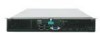
Chapter 2 provides instructions for installing or replacing components such as update the compute module firmware using the Intel® Compute Module MFS5520VI. The back of the product, and product diagrams to assist you identify components and their locations. Manual Organization Chapter 1 provides a brief overview of this manual,see http:// www.intel.com/support/motherboards/server/MFS5520VI/. It provides step-bystep instructions and diagrams for adding and replacing components. This section includes information on hardware diagnostics. This document provides...
Chapter 2 provides instructions for installing or replacing components such as update the compute module firmware using the Intel® Compute Module MFS5520VI. The back of the product, and product diagrams to assist you identify components and their locations. Manual Organization Chapter 1 provides a brief overview of this manual,see http:// www.intel.com/support/motherboards/server/MFS5520VI/. It provides step-bystep instructions and diagrams for adding and replacing components. This section includes information on hardware diagnostics. This document provides...
User Guide
Page 6
... top that you perform all power from the compute module, uninstall or remove the compute module from the chassis. If one is sold. vi Intel® Compute Module MFS5520VI User Guide Use of other products / components will most likely result in place can damage disk drives, boards, and other tool you use to remove a jumper, or you may be extremely sensitive to remove or install a jumper; Some jumpers have such a tab, take care...
... top that you perform all power from the compute module, uninstall or remove the compute module from the chassis. If one is sold. vi Intel® Compute Module MFS5520VI User Guide Use of other products / components will most likely result in place can damage disk drives, boards, and other tool you use to remove a jumper, or you may be extremely sensitive to remove or install a jumper; Some jumpers have such a tab, take care...
User Guide
Page 7
... Component Locations 4 Configuration Jumpers...5 Front Panel Connectors and Indicators 7 Front Panel Indicators ...7 Hardware Requirements ...8 Processor ...8 Memory ...8 Power Supply ...9 Additional Information and Software 10 Hardware Installations and Upgrades 13 Before You Begin ...13 Tools and Supplies Needed ...13 Installation Guidelines ...13 Removing and Installing an Intel® Compute Module MFS5520VI 13 Removing a Compute Module from the Chassis 13 Installing a Compute Module into the Chassis 14 Removing or Installing the Top Cover 14 Removing the Top Cover ...14 Installing...
... Component Locations 4 Configuration Jumpers...5 Front Panel Connectors and Indicators 7 Front Panel Indicators ...7 Hardware Requirements ...8 Processor ...8 Memory ...8 Power Supply ...9 Additional Information and Software 10 Hardware Installations and Upgrades 13 Before You Begin ...13 Tools and Supplies Needed ...13 Installation Guidelines ...13 Removing and Installing an Intel® Compute Module MFS5520VI 13 Removing a Compute Module from the Chassis 13 Installing a Compute Module into the Chassis 14 Removing or Installing the Top Cover 14 Removing the Top Cover ...14 Installing...
User Guide
Page 8
...Compute Module MFS5520VI User Guide Installing and Removing Mezzanine Card 42 Installing the Mezzanine Card 42 Removing a Mezzanine Card 46 Replacing the CMOS Battery 49 BIOS Setup Utility ...53 Starting BIOS Setup Utility 53 If You Cannot Access Setup 53 General Layout and Navigation 53 Setup Menus ...57 Main ...58 Advanced ...60 Security ...73 Server Management ...76 Boot Options ...81 Boot Manager ...84 Error Manager ...85 Exit ...86 Upgrading the BIOS ...88 Preparing for the Upgrade ...88 Clearing the Password ...89 Clearing the CMOS ...92 BIOS Recovery Procedure 93 Troubleshooting...
...Compute Module MFS5520VI User Guide Installing and Removing Mezzanine Card 42 Installing the Mezzanine Card 42 Removing a Mezzanine Card 46 Replacing the CMOS Battery 49 BIOS Setup Utility ...53 Starting BIOS Setup Utility 53 If You Cannot Access Setup 53 General Layout and Navigation 53 Setup Menus ...57 Main ...58 Advanced ...60 Security ...73 Server Management ...76 Boot Options ...81 Boot Manager ...84 Error Manager ...85 Exit ...86 Upgrading the BIOS ...88 Preparing for the Upgrade ...88 Clearing the Password ...89 Clearing the CMOS ...92 BIOS Recovery Procedure 93 Troubleshooting...
User Guide
Page 20
... these pins are jumpered, the compute module boots from the emergency BIOS image. To clear the CMOS, you must then move the jumper to the default position 1-2 and reinstall the compute module into the chassis. These pins should have a jumper in place for normal operation. J9B9: BIOS Recover 1-2 These pins should not be jumpered for normal operation (Default) 2-3 If these pins are jumpered, the CMOS settings are cleared immediately. Enabled 6 Intel® Compute Module MFS5520VI User Guide Table 2. J9A5: BMC Force 1-2 Update 2-3 BMC Firmware Force Update Mode...
... these pins are jumpered, the compute module boots from the emergency BIOS image. To clear the CMOS, you must then move the jumper to the default position 1-2 and reinstall the compute module into the chassis. These pins should have a jumper in place for normal operation. J9B9: BIOS Recover 1-2 These pins should not be jumpered for normal operation (Default) 2-3 If these pins are jumpered, the CMOS settings are cleared immediately. Enabled 6 Intel® Compute Module MFS5520VI User Guide Table 2. J9A5: BMC Force 1-2 Update 2-3 BMC Firmware Force Update Mode...
User Guide
Page 22
Processor The Intel® Compute Module MFS5520VI supports up to two Intel® Xeon® Processors 5500 series or two Intel® Xeon® Processor 5600 series in identifying a compute module from the front panel Indicates drive activity Blue Green NIC1-2 LEDs I /O mezzanine card Green Green Indicator Use the Intel® Modular Server Control software to 12 DIMMs with two DIMMs per channel, thereby supporting up to 95-W Thermal Design Power (TDP): • 4.8 GT/s, 5.86 GT...
Processor The Intel® Compute Module MFS5520VI supports up to two Intel® Xeon® Processors 5500 series or two Intel® Xeon® Processor 5600 series in identifying a compute module from the front panel Indicates drive activity Blue Green NIC1-2 LEDs I /O mezzanine card Green Green Indicator Use the Intel® Modular Server Control software to 12 DIMMs with two DIMMs per channel, thereby supporting up to 95-W Thermal Design Power (TDP): • 4.8 GT/s, 5.86 GT...
User Guide
Page 62
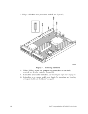
Reinstall the top cover. Removing Standoffs 8. For instructions, see Figure 41). 1 I/O 2 1 2 ID AF003093 Figure 41. Using a Phillips* screwdriver, secure the four screws (that were previously removed) into the Chassis" on page 16. 10. Reinstall the server compute module in the chassis. For instructions, see "Installing a Compute Module into the holes vacated by the standoffs. 9. 7. Using a 1/4-inch nut driver, remove the standoffs (see "Installing the Top Cover" on page 14. 48 Intel® Compute Module MFS5520VI User Guide
Reinstall the top cover. Removing Standoffs 8. For instructions, see Figure 41). 1 I/O 2 1 2 ID AF003093 Figure 41. Using a Phillips* screwdriver, secure the four screws (that were previously removed) into the Chassis" on page 16. 10. Reinstall the server compute module in the chassis. For instructions, see "Installing a Compute Module into the holes vacated by the standoffs. 9. 7. Using a 1/4-inch nut driver, remove the standoffs (see "Installing the Top Cover" on page 14. 48 Intel® Compute Module MFS5520VI User Guide
User Guide
Page 67
.... Power on page -92. When the BIOS Setup Utility is entered, the Main screen is sectioned into functional areas. For instructions on clearing the CMOS, see Section , "Clearing the CMOS" on or reboot the compute module using the Intel® Modular Server Control UI. Each occupies a specific area of the Main screen. Intel® Compute Module MFS5520VI User Guide 53 Before you might need to the Intel® Modular Server System MFSYS25/MFSYS35 User Guide for the Intel® Compute Module MFS5520VI's built-in devices, boot manager, and error manager...
.... Power on page -92. When the BIOS Setup Utility is entered, the Main screen is sectioned into functional areas. For instructions on clearing the CMOS, see Section , "Clearing the CMOS" on or reboot the compute module using the Intel® Modular Server Control UI. Each occupies a specific area of the Main screen. Intel® Compute Module MFS5520VI User Guide 53 Before you might need to the Intel® Modular Server System MFSYS25/MFSYS35 User Guide for the Intel® Compute Module MFS5520VI's built-in devices, boot manager, and error manager...

User Guide
Page 73
... field. Intel® Compute Module MFS5520VI User Guide 59 Displays the current BIOS version. If the logo is the default mode. System Time has configurable fields for Month, Day, and Year. Use the [+] or [-] key to modify the selected field. If no passwords are set, Administrator is displayed during POST. Minor and fatal error displays are in the flash ROM, or if Quiet Boot is disabled, the summary and diagnostic screen is displayed during POST...
... field. Intel® Compute Module MFS5520VI User Guide 59 Displays the current BIOS version. If the logo is the default mode. System Time has configurable fields for Month, Day, and Year. Use the [+] or [-] key to modify the selected field. If no passwords are set, Administrator is displayed during POST. Minor and fatal error displays are in the flash ROM, or if Quiet Boot is disabled, the summary and diagnostic screen is displayed during POST...

User Guide
Page 84
...for the compute module. PCI Configuration The PCI Configuration Screen allows you to be needed . USB device boot support and PS/2 emulation for legacy USB keyboard support when using an OS that is USB unaware. If disabled, this will remove all on -board NIC controllers. 70 Intel® Compute Module MFS5520VI User Guide USB Mass Storage device start unit command time-out. If disabled all USB Mass Storage devices as Boot options. If enabled, this allows all onboard USB controllers are enabled to support USB 2.0 mode. By default, the USB Controller is attached I/O port 60h...
...for the compute module. PCI Configuration The PCI Configuration Screen allows you to be needed . USB device boot support and PS/2 emulation for legacy USB keyboard support when using an OS that is USB unaware. If disabled, this will remove all on -board NIC controllers. 70 Intel® Compute Module MFS5520VI User Guide USB Mass Storage device start unit command time-out. If disabled all USB Mass Storage devices as Boot options. If enabled, this allows all onboard USB controllers are enabled to support USB 2.0 mode. By default, the USB Controller is attached I/O port 60h...

User Guide
Page 86
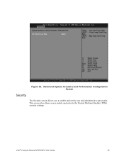
... to boot or wake the system. Specifically the System Acoustics and Performance Configuration screen allows the user to set to CLTT the system is able to accurately control memory temperatures, which is set to configure the DIMM thermal management option for the Intel® Compute Module MFS5520VI. With the Throttling mode set the DIMM throttling mode to highlight System Acoustics and Performance Configuration and press . 72 Intel® Compute Module MFS5520VI User Guide Warning: If [Disabled] is configured only...
... to boot or wake the system. Specifically the System Acoustics and Performance Configuration screen allows the user to set to CLTT the system is able to accurately control memory temperatures, which is set to configure the DIMM thermal management option for the Intel® Compute Module MFS5520VI. With the Throttling mode set the DIMM throttling mode to highlight System Acoustics and Performance Configuration and press . 72 Intel® Compute Module MFS5520VI User Guide Warning: If [Disabled] is configured only...
User Guide
Page 87
This screen also allows you to enable and activate the Trusted Platform Module (TPM) security settings. Intel® Compute Module MFS5520VI User Guide 73 Advanced System Acoustics and Performance Configuration Screen Security The Security screen allows you to enable and set the user and administrative passwords. Figure 53.
This screen also allows you to enable and activate the Trusted Platform Module (TPM) security settings. Intel® Compute Module MFS5520VI User Guide 73 Advanced System Acoustics and Performance Configuration Screen Security The Security screen allows you to enable and set the user and administrative passwords. Figure 53.
User Guide
Page 89
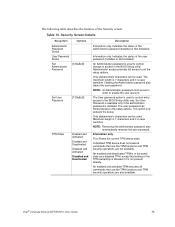
... user password has limited access to enable the user account. Intel® Compute Module MFS5520VI User Guide 75 Indicates the status of the administrator password (Installed or Not Installed). Set User Password is available only if the administrator password is case sensitive. Indicates the status of the user password (Installed or Not Installed). An Administrator password is case sensitive. Only alphanumeric characters can be set in order to the setup options. Maximum length is 7 characters and it is used...
... user password has limited access to enable the user account. Intel® Compute Module MFS5520VI User Guide 75 Indicates the status of the administrator password (Installed or Not Installed). Set User Password is available only if the administrator password is case sensitive. Indicates the status of the user password (Installed or Not Installed). An Administrator password is case sensitive. Only alphanumeric characters can be set in order to the setup options. Maximum length is 7 characters and it is used...

User Guide
Page 91
...; Management Software. Compute module performs a reset. [Power Off] - Intel® Compute Module MFS5520VI User Guide 77 compute module stays off . If enabled, this driver. If the OS watchdog timer is enabled, this is reset to the same state before the timer expires, the BMC resets the compute module. If the OS watchdog timer is enabled, this is logged. All current entries are lost after a reboot. Do not enable if your OS does not support this option clears...
...; Management Software. Compute module performs a reset. [Power Off] - Intel® Compute Module MFS5520VI User Guide 77 compute module stays off . If enabled, this driver. If the OS watchdog timer is enabled, this is reset to the same state before the timer expires, the BMC resets the compute module. If the OS watchdog timer is enabled, this is logged. All current entries are lost after a reboot. Do not enable if your OS does not support this option clears...
User Guide
Page 102
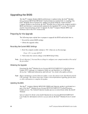
Updating the BIOS The Intel® Compute Module MFS5520VI BIOS and firmware update is started from within the Intel® Modular Server Control UI. Preparing for a link to access and use the Intel® Modular Server Control UI. 88 Intel® Compute Module MFS5520VI User Guide Obtaining the Upgrade Download the Intel® Modular Server System MFSYS25/MFSYS35 Unified Firmware Update (UFU) package to a temporary folder on how to the update software. The release notes may contain critical information regarding specific fixes, or other...
Updating the BIOS The Intel® Compute Module MFS5520VI BIOS and firmware update is started from within the Intel® Modular Server Control UI. Preparing for a link to access and use the Intel® Modular Server Control UI. 88 Intel® Compute Module MFS5520VI User Guide Obtaining the Upgrade Download the Intel® Modular Server System MFSYS25/MFSYS35 Unified Firmware Update (UFU) package to a temporary folder on how to the update software. The release notes may contain critical information regarding specific fixes, or other...
User Guide
Page 107
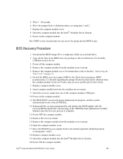
... the compute modules USB ports. 10. Power on the compute module. 11. Remove the compute module cover. Details regarding the jumper ID and location can reset it by going into the BIOS setup. Remove the recovery media. 15. Replace compute module cover. 19. Insert compute module back into the Intel® Modular Server System. 9. Download the BIOS image file to the 'Boot from the compute module Technical Product Specification and the Quick Start Guide. 7. Power on the compute module. Insert the compute module into the modular server system. 9. 5. Startup.nsh...
... the compute modules USB ports. 10. Power on the compute module. 11. Remove the compute module cover. Details regarding the jumper ID and location can reset it by going into the BIOS setup. Remove the recovery media. 15. Replace compute module cover. 19. Insert compute module back into the Intel® Modular Server System. 9. Download the BIOS image file to the 'Boot from the compute module Technical Product Specification and the Quick Start Guide. 7. Power on the compute module. Insert the compute module into the modular server system. 9. 5. Startup.nsh...

User Guide
Page 109
...; Compute Module MFS5520VI User Guide 95 Before performing extensive troubleshooting steps, ensure that the BIOS and BMC firmware code, and device drivers are up to date. Try resetting your compute module using one of server function issues is the add-in mezzanine card fully seated in the connectors on the server board? • Are all jumper settings on to clear the memory, restart POST, reload the operating system, and halt power to all installed components and the installed operating system listed...
...; Compute Module MFS5520VI User Guide 95 Before performing extensive troubleshooting steps, ensure that the BIOS and BMC firmware code, and device drivers are up to date. Try resetting your compute module using one of server function issues is the add-in mezzanine card fully seated in the connectors on the server board? • Are all jumper settings on to clear the memory, restart POST, reload the operating system, and halt power to all installed components and the installed operating system listed...

User Guide
Page 110
... for the following problems: • Power LED does not light • No video display • Characters on the screen appear distorted or incorrect • No available storage • Network problems Try the solutions in either a USB floppy drive or a USB CD-ROM drive. 6. Verify that the chassis power supplies are on. 4. Specific Problems and Corrective Actions This section provides possible solutions for additional help. 96 Intel® Compute Module MFS5520VI User Guide Hardware Diagnostic Testing This section...
... for the following problems: • Power LED does not light • No video display • Characters on the screen appear distorted or incorrect • No available storage • Network problems Try the solutions in either a USB floppy drive or a USB CD-ROM drive. 6. Verify that the chassis power supplies are on. 4. Specific Problems and Corrective Actions This section provides possible solutions for additional help. 96 Intel® Compute Module MFS5520VI User Guide Hardware Diagnostic Testing This section...
User Guide
Page 112
.... See the software documentation. • Make sure the software is properly installed and configured for the software. See the software documentation. 98 Intel® Compute Module MFS5520VI User Guide Mezzanine Card Stops Working Without Apparent Cause • Try re-seating the mezzanine card. • The network driver files may be corrupt or deleted. Refer to the Intel® Modular Server System MFSYS25/ MFSYS35 and Intel® Compute Module MFS5000SI/MFS5520VI Tested Hardware and Operating System List for validation...
.... See the software documentation. • Make sure the software is properly installed and configured for the software. See the software documentation. 98 Intel® Compute Module MFS5520VI User Guide Mezzanine Card Stops Working Without Apparent Cause • Try re-seating the mezzanine card. • The network driver files may be corrupt or deleted. Refer to the Intel® Modular Server System MFSYS25/ MFSYS35 and Intel® Compute Module MFS5000SI/MFS5520VI Tested Hardware and Operating System List for validation...

User Guide
Page 113
...; Compute Module MFS5520VI User Guide 99 • Use only an authorized copy. Devices are installed. • If you may be getting random errors in data files: If you are running it again. If you are getting corrupted by default. Note: Random errors in your power line. Unauthorized copies often do not work. • If you are experiencing any of voltage spikes include a flickering video display, unexpected reboots...
...; Compute Module MFS5520VI User Guide 99 • Use only an authorized copy. Devices are installed. • If you may be getting random errors in data files: If you are running it again. If you are getting corrupted by default. Note: Random errors in your power line. Unauthorized copies often do not work. • If you are experiencing any of voltage spikes include a flickering video display, unexpected reboots...


