User Guide
Page 2
... in the United States and other application in any medical, life saving, or life sustaining applications or for use Intel developed server building blocks to consult vendor datasheets and operating parameters to use in which the failure of their specific application and ...environmental conditions. Except as the property of others. Intel® server boards contain a number of any express or implied warranty, relating to sale and/or use of Intel® products including liability or warranties relating to fitness for a particular purpose...
... in the United States and other application in any medical, life saving, or life sustaining applications or for use Intel developed server building blocks to consult vendor datasheets and operating parameters to use in which the failure of their specific application and ...environmental conditions. Except as the property of others. Intel® server boards contain a number of any express or implied warranty, relating to sale and/or use of Intel® products including liability or warranties relating to fitness for a particular purpose...
User Guide
Page 3
... les mises en garde indiquées dans ce document avant de suivre toute instruction. Intel® Compute Module MFS5000SI User Guide iii Beachten Sie hierzu auch die Intel® Server Boards and Server Chassis Safety Information unter http://support.intel.com/support/ motherboards/server/sb/cs-010770.htm. Wichtige Sicherheitshinweise Lesen Sie zunächst sämtliche Warnund...
... les mises en garde indiquées dans ce document avant de suivre toute instruction. Intel® Compute Module MFS5000SI User Guide iii Beachten Sie hierzu auch die Intel® Server Boards and Server Chassis Safety Information unter http://support.intel.com/support/ motherboards/server/sb/cs-010770.htm. Wichtige Sicherheitshinweise Lesen Sie zunächst sämtliche Warnund...
User Guide
Page 4
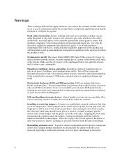
...by wearing an anti-static wrist strap attached to remove or install a jumper; Gripping the wide sides can result. iv Intel® Compute Module MFS5000SI User Guide Warnings These warnings and cautions apply whenever you perform all procedures in this document only at an ESD workstation. ... of the jumper with , but not squeeze, the pliers or other parts. Take care to ESD. operating it . If your server product, whether you must adhere to ensure and maintain compliance with the cover removed; ESD and handling electronic devices: Always handle electronic devices...
...by wearing an anti-static wrist strap attached to remove or install a jumper; Gripping the wide sides can result. iv Intel® Compute Module MFS5000SI User Guide Warnings These warnings and cautions apply whenever you perform all procedures in this document only at an ESD workstation. ... of the jumper with , but not squeeze, the pliers or other parts. Take care to ESD. operating it . If your server product, whether you must adhere to ensure and maintain compliance with the cover removed; ESD and handling electronic devices: Always handle electronic devices...
User Guide
Page 5
... ...5 Processor ...5 Memory ...5 Power Supply ...6 Hardware Installations and Upgrades 7 Before You Begin ...7 Tools and Supplies Needed ...7 Installation Guidelines ...7 Removing and Installing an Intel® Compute Module MFS5000SI 7 Removing a Compute Module from the Server System 7 Installing a Compute Module into the Server System 8 Opening and Closing the Top Cover 8 Opening and Removing the Top Cover 8 Replacing and Closing the Top Cover 10 Installing...
... ...5 Processor ...5 Memory ...5 Power Supply ...6 Hardware Installations and Upgrades 7 Before You Begin ...7 Tools and Supplies Needed ...7 Installation Guidelines ...7 Removing and Installing an Intel® Compute Module MFS5000SI 7 Removing a Compute Module from the Server System 7 Installing a Compute Module into the Server System 8 Opening and Closing the Top Cover 8 Opening and Removing the Top Cover 8 Replacing and Closing the Top Cover 10 Installing...
User Guide
Page 6
...Electro Magnetic Compatibility (EMC) / Harmonic Requirements 57 Product Ecology Requirements 57 Component Regulatory Requirements Needed to a Compute Module 44 Problems with Newly Installed Application Software 45 Problems with Application Software that Previously Functioned Properly 45 Devices are......61 Server Safety Information ...61 Safety Warnings and Cautions 61 Intended Application Uses ...62 Site Selection ...62 Equipment Handling Practices 62 Power and Electrical Warnings 62 System Access Warnings ...63 Rack Mount Warnings ...64 vi Intel® Compute Module MFS5000SI User ...
...Electro Magnetic Compatibility (EMC) / Harmonic Requirements 57 Product Ecology Requirements 57 Component Regulatory Requirements Needed to a Compute Module 44 Problems with Newly Installed Application Software 45 Problems with Application Software that Previously Functioned Properly 45 Devices are......61 Server Safety Information ...61 Safety Warnings and Cautions 61 Intended Application Uses ...62 Site Selection ...62 Equipment Handling Practices 62 Power and Electrical Warnings 62 System Access Warnings ...63 Rack Mount Warnings ...64 vi Intel® Compute Module MFS5000SI User ...
User Guide
Page 11
...Figure 23. CMOS Battery Location 40 Intel® Compute Module MFS5000SI User Guide xi Removing DIMMs...30 Figure 34. Removing Screws from Mezzanine Card 36 Figure 40. Removing Mezzanine Card 37 Figure 41. Removing Screws from Server Board 32 Figure 36. Installing Mezzanine ...Card 34 Figure 38. Opening Load Plate 20 Figure 22. DIMM Slot Order ...25 Figure 29. Intel® Compute Module MFS5000SI 1 Figure 2. Opening Load Plate 12 Figure 11...
...Figure 23. CMOS Battery Location 40 Intel® Compute Module MFS5000SI User Guide xi Removing DIMMs...30 Figure 34. Removing Screws from Mezzanine Card 36 Figure 40. Removing Mezzanine Card 37 Figure 41. Removing Screws from Server Board 32 Figure 36. Installing Mezzanine ...Card 34 Figure 38. Opening Load Plate 20 Figure 22. DIMM Slot Order ...25 Figure 29. Intel® Compute Module MFS5000SI 1 Figure 2. Opening Load Plate 12 Figure 11...
User Guide
Page 13
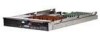
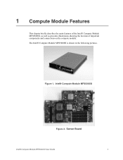
Figure 1. 1 Compute Module Features This chapter briefly describes the main features of the Intel® Compute Module MFS5000SI, as well as provides illustrations showing the location of important components and connections on the compute module. Server Board Intel® Compute Module MFS5000SI User Guide 1 The Intel® Compute Module MFS5000SI is shown in the following pictures. Intel® Compute Module MFS5000SI Figure 2.
Figure 1. 1 Compute Module Features This chapter briefly describes the main features of the Intel® Compute Module MFS5000SI, as well as provides illustrations showing the location of important components and connections on the compute module. Server Board Intel® Compute Module MFS5000SI User Guide 1 The Intel® Compute Module MFS5000SI is shown in the following pictures. Intel® Compute Module MFS5000SI Figure 2.
User Guide
Page 14
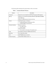
... controller with 16MB onboard memory LSI* 1064e SAS controller Intel® 8256EB dual port controller Trusted Platform Module, version 1.2 2 Intel® Compute Module MFS5000SI User Guide Table 1. Compute Module Features Feature Processors Memory Chipset Peripheral Interfaces Video Hard Drive LAN Trusted Computing Description Support for up to two Dual-Core Intel® Xeon® processors 5000 sequence Support for up...
... controller with 16MB onboard memory LSI* 1064e SAS controller Intel® 8256EB dual port controller Trusted Platform Module, version 1.2 2 Intel® Compute Module MFS5000SI User Guide Table 1. Compute Module Features Feature Processors Memory Chipset Peripheral Interfaces Video Hard Drive LAN Trusted Computing Description Support for up to two Dual-Core Intel® Xeon® processors 5000 sequence Support for up...
User Guide
Page 19
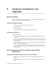
Green on a component indicates a touch point, where you must first shut down the operating system and turn off the compute module. If the compute module is operating, shut down the operating system and power it from the server. 4. Intel® Compute Module MFS5000SI User Guide 7 Tools and Supplies Needed • Phillips* (cross head) screwdriver (#1 bit and #2 bit • 1/4-inch nut...
Green on a component indicates a touch point, where you must first shut down the operating system and turn off the compute module. If the compute module is operating, shut down the operating system and power it from the server. 4. Intel® Compute Module MFS5000SI User Guide 7 Tools and Supplies Needed • Phillips* (cross head) screwdriver (#1 bit and #2 bit • 1/4-inch nut...
User Guide
Page 20
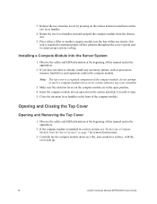
... the two retention levers by pressing on a flat, non-conductive surface, with the cover side up. 8 Intel® Compute Module MFS5000SI User Guide Installing a Compute Module into a server system without a top cover installed. 3. Note: The top cover is installed in the compute module. Close the retention lever handles on page 7 for removal instructions. 3. Observe the safety and ESD information...
... the two retention levers by pressing on a flat, non-conductive surface, with the cover side up. 8 Intel® Compute Module MFS5000SI User Guide Installing a Compute Module into a server system without a top cover installed. 3. Note: The top cover is installed in the compute module. Close the retention lever handles on page 7 for removal instructions. 3. Observe the safety and ESD information...
User Guide
Page 21
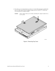
B A 1 I/O 2 1 2 ID Figure 6. Caution: Always replace the top cover before installing the compute module into a server system. 4. Removing Top Cover AF002402 Intel® Compute Module MFS5000SI User Guide 9 Press the top cover release button (see letter "A" in the following figure) and slide the top cover back, away from the compute module bezel (see letter "B"). Lift the top cover up and off the compute module.
B A 1 I/O 2 1 2 ID Figure 6. Caution: Always replace the top cover before installing the compute module into a server system. 4. Removing Top Cover AF002402 Intel® Compute Module MFS5000SI User Guide 9 Press the top cover release button (see letter "A" in the following figure) and slide the top cover back, away from the compute module bezel (see letter "B"). Lift the top cover up and off the compute module.
User Guide
Page 23
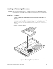
..." on page 7 for use in the appendices. 2. Observe the safety and ESD information at the beginning of this manual and in the Intel® Compute Module MFS5000SI should be installed. For instructions, see "Removing a Compute Module from the Server System" on page 8. 4. Installing or Replacing a Processor Caution: Only processors validated for removal instructions. 3. Removing Processor Air Duct...
..." on page 7 for use in the appendices. 2. Observe the safety and ESD information at the beginning of this manual and in the Intel® Compute Module MFS5000SI should be installed. For instructions, see "Removing a Compute Module from the Server System" on page 8. 4. Installing or Replacing a Processor Caution: Only processors validated for removal instructions. 3. Removing Processor Air Duct...
User Guide
Page 29
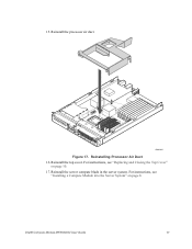
Reinstall the processor air duct. 1 I/O 2 1 2 ID AF002405 Figure 17. 15. Reinstall the top cover. Reinstalling Processor Air Duct 16. Reinstall the server compute blade in the server system. Intel® Compute Module MFS5000SI User Guide 17 For instructions, see "Installing a Compute Module into the Server System" on page 10. 17. For instructions, see "Replacing and Closing the Top Cover" on page 8.
Reinstall the processor air duct. 1 I/O 2 1 2 ID AF002405 Figure 17. 15. Reinstall the top cover. Reinstalling Processor Air Duct 16. Reinstall the server compute blade in the server system. Intel® Compute Module MFS5000SI User Guide 17 For instructions, see "Installing a Compute Module into the Server System" on page 10. 17. For instructions, see "Replacing and Closing the Top Cover" on page 8.
User Guide
Page 30
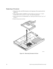
Replacing a Processor 1. For instructions, see "Removing a Compute Module from the Server System" on page 8. 4. Remove the processor air duct. 1 I/O 2 1 2 ID Figure 18. Removing Processor Air Duct AF002404 18 Intel® Compute Module MFS5000SI User Guide Observe the safety and ESD information at the beginning of this manual and in a server system, see "Opening and Removing the Top Cover" on page 7 for removal instructions. 3. Remove the top cover. If the compute module is installed in the appendices. 2.
Replacing a Processor 1. For instructions, see "Removing a Compute Module from the Server System" on page 8. 4. Remove the processor air duct. 1 I/O 2 1 2 ID Figure 18. Removing Processor Air Duct AF002404 18 Intel® Compute Module MFS5000SI User Guide Observe the safety and ESD information at the beginning of this manual and in a server system, see "Opening and Removing the Top Cover" on page 7 for removal instructions. 3. Remove the top cover. If the compute module is installed in the appendices. 2.

User Guide
Page 35
Reinstall the processor air duct. 1 I/O 2 1 2 ID AF002405 Figure 27. Reinstall the server compute blade in the server system. Reinstalling Processor Air Duct 16. Reinstall the top cover. Intel® Compute Module MFS5000SI User Guide 23 15. For instructions, see "Installing a Compute Module into the Server System" on page 10. 17. For instructions, see "Replacing and Closing the Top Cover" on page 8.
Reinstall the processor air duct. 1 I/O 2 1 2 ID AF002405 Figure 27. Reinstall the server compute blade in the server system. Reinstalling Processor Air Duct 16. Reinstall the top cover. Intel® Compute Module MFS5000SI User Guide 23 15. For instructions, see "Installing a Compute Module into the Server System" on page 10. 17. For instructions, see "Replacing and Closing the Top Cover" on page 8.
User Guide
Page 36
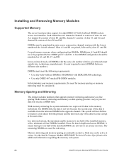
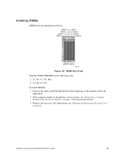
...Use only fully-buffered DIMMs (FB-DIMMs) with DDR2 DRAM technology. • Use only DDR2-667 stacked FB-DIMM modules. See the Intel® Compute Module MFS5000SI Technical Product Specification for mirroring. For performance reasons, when configuring four DIMMs, DIMM pair A2 and B2 should be populated ... maximum usable memory is not required to one can be active at the same time. Installing and Removing Memory Modules Supported Memory The server board provides support for eight DDR2-667 fully-buffered DIMM sockets across consecutive channels starting with the lowest numbered slot...
...Use only fully-buffered DIMMs (FB-DIMMs) with DDR2 DRAM technology. • Use only DDR2-667 stacked FB-DIMM modules. See the Intel® Compute Module MFS5000SI Technical Product Specification for mirroring. For performance reasons, when configuring four DIMMs, DIMM pair A2 and B2 should be populated ... maximum usable memory is not required to one can be active at the same time. Installing and Removing Memory Modules Supported Memory The server board provides support for eight DDR2-667 fully-buffered DIMM sockets across consecutive channels starting with the lowest numbered slot...
User Guide
Page 37
For instructions, see "Removing a Compute Module from the Server System" on page 8. Intel® Compute Module MFS5000SI User Guide 25 Observe the safety and ESD information at the beginning of this manual and in the following order: 1. Installing DIMMs DIMM slots ... 0 Branch 1 AF002452 Figure 28. A1, B1, C1, D1, then 2. Remove the top cover. DIMM Slot Order Populate DDR2 FBDIMMs in the appendices. 2. If the compute module is installed in a server system, see "Opening and Removing the Top Cover" on page 7 for removal instructions. 3. A2, B2, C2, D2 To install DIMMs: 1.
For instructions, see "Removing a Compute Module from the Server System" on page 8. Intel® Compute Module MFS5000SI User Guide 25 Observe the safety and ESD information at the beginning of this manual and in the following order: 1. Installing DIMMs DIMM slots ... 0 Branch 1 AF002452 Figure 28. A1, B1, C1, D1, then 2. Remove the top cover. DIMM Slot Order Populate DDR2 FBDIMMs in the appendices. 2. If the compute module is installed in a server system, see "Opening and Removing the Top Cover" on page 7 for removal instructions. 3. A2, B2, C2, D2 To install DIMMs: 1.
User Guide
Page 40
Reinstalling Processor Air Duct 9. Reinstall the top cover. For instructions, see "Installing a Compute Module into the Server System" on page 10. 10. For instructions, see "Replacing and Closing the Top Cover" on page 8. 28 Intel® Compute Module MFS5000SI User Guide Reinstall the server compute blade in the server system. Reinstall the processor air duct. 1 I/O 2 1 2 ID AF002405 Figure 31. 8.
Reinstalling Processor Air Duct 9. Reinstall the top cover. For instructions, see "Installing a Compute Module into the Server System" on page 10. 10. For instructions, see "Replacing and Closing the Top Cover" on page 8. 28 Intel® Compute Module MFS5000SI User Guide Reinstall the server compute blade in the server system. Reinstall the processor air duct. 1 I/O 2 1 2 ID AF002405 Figure 31. 8.
User Guide
Page 41
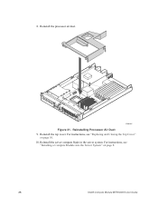
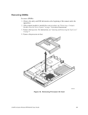
If the compute module is installed in the appendices. 2. For instructions, see "Removing a Compute Module from the Server System" on page 8. 4. Remove the top cover. Removing Processor Air Duct AF002404 Intel® Compute Module MFS5000SI User Guide 29 Removing DIMMs To remove DIMMs: 1. Remove the processor air duct. 1 I/O 2 1 2 ID Figure 32. Observe the safety and ESD information at the beginning of this manual and in a server system, see "Opening and Removing the Top Cover" on page 7 for removal instructions. 3.
If the compute module is installed in the appendices. 2. For instructions, see "Removing a Compute Module from the Server System" on page 8. 4. Remove the top cover. Removing Processor Air Duct AF002404 Intel® Compute Module MFS5000SI User Guide 29 Removing DIMMs To remove DIMMs: 1. Remove the processor air duct. 1 I/O 2 1 2 ID Figure 32. Observe the safety and ESD information at the beginning of this manual and in a server system, see "Opening and Removing the Top Cover" on page 7 for removal instructions. 3.

User Guide
Page 43
6. For instructions, see "Installing a Compute Module into the Server System" on page 10. 8. Reinstall the top cover. For instructions, see "Replacing and Closing the Top Cover" on page 8. Reinstall the server compute blade in the server system. Intel® Compute Module MFS5000SI User Guide 31 Reinstalling Processor Air Duct 7. Reinstall the processor air duct. 1 I/O 2 1 2 ID AF002405 Figure 34.
6. For instructions, see "Installing a Compute Module into the Server System" on page 10. 8. Reinstall the top cover. For instructions, see "Replacing and Closing the Top Cover" on page 8. Reinstall the server compute blade in the server system. Intel® Compute Module MFS5000SI User Guide 31 Reinstalling Processor Air Duct 7. Reinstall the processor air duct. 1 I/O 2 1 2 ID AF002405 Figure 34.

