User Guide
Page 4
... your system when handling parts. Use of other products / components will void the UL listing and other resource as a reference, pay close attention to remove or install a jumper; Hazardous conditions, devices and cables: Hazardous electrical conditions may bend or break the pins on top that you remove the compute module enclosure cover to access components inside the jumper, causing intermittent problems with the function controlled by wearing an...
... your system when handling parts. Use of other products / components will void the UL listing and other resource as a reference, pay close attention to remove or install a jumper; Hazardous conditions, devices and cables: Hazardous electrical conditions may bend or break the pins on top that you remove the compute module enclosure cover to access components inside the jumper, causing intermittent problems with the function controlled by wearing an...
User Guide
Page 5
... Locations 3 Configuration Jumpers...4 Front Panel Connectors and Indicators 5 Hardware Requirements ...5 Processor ...5 Memory ...5 Power Supply ...6 Hardware Installations and Upgrades 7 Before You Begin ...7 Tools and Supplies Needed ...7 Installation Guidelines ...7 Removing and Installing an Intel® Compute Module MFS5000SI 7 Removing a Compute Module from the Server System 7 Installing a Compute Module into the Server System 8 Opening and Closing the Top Cover 8 Opening and Removing the Top Cover 8 Replacing and Closing the Top Cover 10 Installing or Replacing a Processor...
... Locations 3 Configuration Jumpers...4 Front Panel Connectors and Indicators 5 Hardware Requirements ...5 Processor ...5 Memory ...5 Power Supply ...6 Hardware Installations and Upgrades 7 Before You Begin ...7 Tools and Supplies Needed ...7 Installation Guidelines ...7 Removing and Installing an Intel® Compute Module MFS5000SI 7 Removing a Compute Module from the Server System 7 Installing a Compute Module into the Server System 8 Opening and Closing the Top Cover 8 Opening and Removing the Top Cover 8 Replacing and Closing the Top Cover 10 Installing or Replacing a Processor...
User Guide
Page 6
... 57 Component Regulatory Requirements Needed to a Compute Module 44 Problems with Newly Installed Application Software 45 Problems with Application Software that Previously Functioned Properly 45 Devices are Not Recognized within the Operating System 45 Diagnostic LED Information ...46 BIOS POST Beep Codes ...46 A Getting Help ...49 World Wide Web ...49 Telephone ...49 U.S. Hardware Diagnostic Testing 42 Specific Problems and Corrective Actions 42 Power LED Does Not Light ...43 No Video Display ...43 Characters are Distorted...
... 57 Component Regulatory Requirements Needed to a Compute Module 44 Problems with Newly Installed Application Software 45 Problems with Application Software that Previously Functioned Properly 45 Devices are Not Recognized within the Operating System 45 Diagnostic LED Information ...46 BIOS POST Beep Codes ...46 A Getting Help ...49 World Wide Web ...49 Telephone ...49 U.S. Hardware Diagnostic Testing 42 Specific Problems and Corrective Actions 42 Power LED Does Not Light ...43 No Video Display ...43 Characters are Distorted...
User Guide
Page 11
... Figure 33. Removing Screws from Mezzanine Card 36 Figure 40. Securing Mezzanine Card to Standoffs 35 Figure 39. Configuration Jumper Locations 4 Figure 5. Reinstalling Processor Air Duct 28 Figure 32. Removing Screws from Server Board 32 Figure 36. Intel® Compute Module MFS5000SI 1 Figure 2. Front Panel Connectors and Indicators 5 Figure 6. Removing Second Processor Air Baffle 16 Figure 17. Lowering Load Plate and Socket Lever 21 Figure 26. Installing Standoffs for...
... Figure 33. Removing Screws from Mezzanine Card 36 Figure 40. Securing Mezzanine Card to Standoffs 35 Figure 39. Configuration Jumper Locations 4 Figure 5. Reinstalling Processor Air Duct 28 Figure 32. Removing Screws from Server Board 32 Figure 36. Intel® Compute Module MFS5000SI 1 Figure 2. Front Panel Connectors and Indicators 5 Figure 6. Removing Second Processor Air Baffle 16 Figure 17. Lowering Load Plate and Socket Lever 21 Figure 26. Installing Standoffs for...
User Guide
Page 14
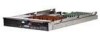
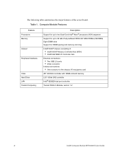
... Intel® 6321ESB I/O Controller Hub External connections: • Two USB 2.0 ports • Video connector Internal connections: • One connector to the chassis I/O mezzanine card ATI* ES1000 controller with 16MB onboard memory LSI* 1064e SAS controller Intel® 8256EB dual port controller Trusted Platform Module, version 1.2 2 Intel® Compute Module MFS5000SI User Guide Table 1. Compute Module Features Feature Processors Memory Chipset Peripheral Interfaces Video Hard Drive LAN Trusted Computing Description Support for up to two Dual-Core Intel® Xeon® processors...
... Intel® 6321ESB I/O Controller Hub External connections: • Two USB 2.0 ports • Video connector Internal connections: • One connector to the chassis I/O mezzanine card ATI* ES1000 controller with 16MB onboard memory LSI* 1064e SAS controller Intel® 8256EB dual port controller Trusted Platform Module, version 1.2 2 Intel® Compute Module MFS5000SI User Guide Table 1. Compute Module Features Feature Processors Memory Chipset Peripheral Interfaces Video Hard Drive LAN Trusted Computing Description Support for up to two Dual-Core Intel® Xeon® processors...
User Guide
Page 16
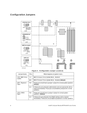
... for normal system operation (Default) If these pins are jumpered, administrator and user passwords will be cleared immediately. These pins should not be jumpered for normal operation. These pins should not be jumpered for normal operation. 4 Intel® Compute Module MFS5000SI User Guide Enabled BMC Firmware Force Update Mode - Configuration Jumpers Fi BIOS Bank Select 32 Default BOOT FROM EMERGENCY BIOS IMAGE J3A3 PASSWORD CLR Default 2 CLEAR 3 PASSWORD J4A1 BMC Force Update 23 Enabled Default Disabled J7A1 CMOS CLR 32 CLEAR Default CMOS J1F2 AF002220 Figure...
... for normal system operation (Default) If these pins are jumpered, administrator and user passwords will be cleared immediately. These pins should not be jumpered for normal operation. These pins should not be jumpered for normal operation. 4 Intel® Compute Module MFS5000SI User Guide Enabled BMC Firmware Force Update Mode - Configuration Jumpers Fi BIOS Bank Select 32 Default BOOT FROM EMERGENCY BIOS IMAGE J3A3 PASSWORD CLR Default 2 CLEAR 3 PASSWORD J4A1 BMC Force Update 23 Enabled Default Disabled J7A1 CMOS CLR 32 CLEAR Default CMOS J1F2 AF002220 Figure...
User Guide
Page 17
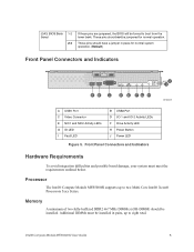
...; Compute Module MFS5000SI User Guide 5 Processor The Intel® Compute Module MFS5000SI supports up to boot from the lower bank. Front Panel Connectors and Indicators Hardware Requirements To avoid integration difficulties and possible board damage, your system must be jumpered for normal system operation. (Default) Front Panel Connectors and Indicators J I AB C D E FG H AF002408 A USB1 Port C Video Connector E NIC1 and NIC2 Activity LEDs G ID LED I Fault LED B USB2 Port D I/O 1 and I/O 2 Activity LEDs F Drive Activity LED H Power Button J Power LED Figure 5. J3A3: BIOS...
...; Compute Module MFS5000SI User Guide 5 Processor The Intel® Compute Module MFS5000SI supports up to boot from the lower bank. Front Panel Connectors and Indicators Hardware Requirements To avoid integration difficulties and possible board damage, your system must be jumpered for normal system operation. (Default) Front Panel Connectors and Indicators J I AB C D E FG H AF002408 A USB1 Port C Video Connector E NIC1 and NIC2 Activity LEDs G ID LED I Fault LED B USB2 Port D I/O 1 and I/O 2 Activity LEDs F Drive Activity LED H Power Button J Power LED Figure 5. J3A3: BIOS...
User Guide
Page 19
... down the operating system and turn off the compute module. Intel® Compute Module MFS5000SI User Guide 7 You do not have to install or remove it down the operating system and power it from the server. 4. Blue on a component indicates that the component may be hot-swapped. Removing and Installing an Intel® Compute Module MFS5000SI Removing a Compute Module from the chassis; Observe the safety and ESD information at the beginning of this manual and...
... down the operating system and turn off the compute module. Intel® Compute Module MFS5000SI User Guide 7 You do not have to install or remove it down the operating system and power it from the server. 4. Blue on a component indicates that the component may be hot-swapped. Removing and Installing an Intel® Compute Module MFS5000SI Removing a Compute Module from the chassis; Observe the safety and ESD information at the beginning of this manual and...
User Guide
Page 20
... a compute module into an open position. 4. If you have not done so already, install any necessary options, such as processors, memory, hard drives and expansion cards in a server system, see "Removing a Compute Module from the chassis slot. 5. Note: The top cover is installed in the compute module. do not attempt to ensure proper system cooling. Insert the compute module into a server system without a top cover installed. 3. Close the retention lever handles on the release button located...
... a compute module into an open position. 4. If you have not done so already, install any necessary options, such as processors, memory, hard drives and expansion cards in a server system, see "Removing a Compute Module from the chassis slot. 5. Note: The top cover is installed in the compute module. do not attempt to ensure proper system cooling. Insert the compute module into a server system without a top cover installed. 3. Close the retention lever handles on the release button located...
User Guide
Page 36
... any one -half of the installed DIMMs are used for additional information regarding the memory sub-system. 24 Intel® Compute Module MFS5000SI User Guide In determining your memory requirements, the need for memory sparing or memory mirroring must be populated as A1 and B1; Memory mirroring and memory sparing are paired, followed by slots C1 and D1. See the Intel® Compute Module MFS5000SI Technical Product Specification for mirroring. channel C consists...
... any one -half of the installed DIMMs are used for additional information regarding the memory sub-system. 24 Intel® Compute Module MFS5000SI User Guide In determining your memory requirements, the need for memory sparing or memory mirroring must be populated as A1 and B1; Memory mirroring and memory sparing are paired, followed by slots C1 and D1. See the Intel® Compute Module MFS5000SI Technical Product Specification for mirroring. channel C consists...
User Guide
Page 46
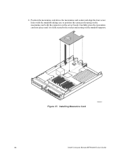
Position the mezzanine card above the mezzanine card socket and align the four screw holes with the standoffs taking care to position the connector housing on the mezzanine card with the connector on the standoff supports. 1 I/O 2 1 2 ID Figure 37. Installing Mezzanine Card AF002407 34 Intel® Compute Module MFS5000SI User Guide 8. Carefully press the mezzanine card into place until it is fully seated in the socket and resting on the server board.
Position the mezzanine card above the mezzanine card socket and align the four screw holes with the standoffs taking care to position the connector housing on the mezzanine card with the connector on the standoff supports. 1 I/O 2 1 2 ID Figure 37. Installing Mezzanine Card AF002407 34 Intel® Compute Module MFS5000SI User Guide 8. Carefully press the mezzanine card into place until it is fully seated in the socket and resting on the server board.
User Guide
Page 53
... installed operating system listed in the BIOS Setup correct? • Is the operating system properly loaded? Intel® Compute Module MFS5000SI User Guide 41 Refer to reboot the system; Cold boot reset. try resetting your system using one of server function issues is to the operating system documentation. • Are all device drivers properly installed? • Are all peripherals. Power off and then on the server board correct? • Are the configuration settings defined in the Intel® Compute Module MFS5000SI Tested Hardware...
... installed operating system listed in the BIOS Setup correct? • Is the operating system properly loaded? Intel® Compute Module MFS5000SI User Guide 41 Refer to reboot the system; Cold boot reset. try resetting your system using one of server function issues is to the operating system documentation. • Are all device drivers properly installed? • Are all peripherals. Power off and then on the server board correct? • Are the configuration settings defined in the Intel® Compute Module MFS5000SI Tested Hardware...
User Guide
Page 54
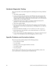
... contrast controls to boot and emits a series of the compute module. If the power LED does not light, see the documentation supplied with your service representative or authorized dealer for additional help. 42 Intel® Compute Module MFS5000SI User Guide If you cannot correct the problem, contact your video display monitor). 3. Turn on . 4. Turn on the screen appear distorted or incorrect • No available storage • Network problems Try the solutions in a USB floppy drive or a USB CDROM drive...
... contrast controls to boot and emits a series of the compute module. If the power LED does not light, see the documentation supplied with your service representative or authorized dealer for additional help. 42 Intel® Compute Module MFS5000SI User Guide If you cannot correct the problem, contact your video display monitor). 3. Turn on . 4. Turn on the screen appear distorted or incorrect • No available storage • Network problems Try the solutions in a USB floppy drive or a USB CDROM drive...
User Guide
Page 55
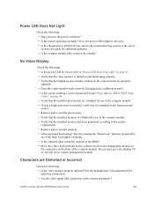
... processor socket. • Remove and re-seat the processor(s). • Verify that the installed memory is working. • Is the onboard video controller enabled in the chassis? See the manufacturer's documentation for use in the compute module. • If only a single processor is turned on and functioning properly. • Verify that the installed processor(s) are Distorted or Incorrect Check the following : • Is the power LED lit? Intel® Compute Module MFS5000SI User Guide...
... processor socket. • Remove and re-seat the processor(s). • Verify that the installed memory is working. • Is the onboard video controller enabled in the chassis? See the manufacturer's documentation for use in the compute module. • If only a single processor is turned on and functioning properly. • Verify that the installed processor(s) are Distorted or Incorrect Check the following : • Is the power LED lit? Intel® Compute Module MFS5000SI User Guide...
User Guide
Page 56
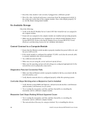
... the Intel® Modular Server System MFSYS25 Tested Hardware and Operating System List for the network the server is properly installed in a different compute module. Cannot Connect to a Compute Module • Ensure that the Ethernet switch module is properly installed, the power LED is lit, and the error LED is not lit. • If the switch module is configured for multiple VLANS, verify that the network driver is configured properly within the operating system. Does video display properly? Mezzanine Card Stops Working Without...
... the Intel® Modular Server System MFSYS25 Tested Hardware and Operating System List for the network the server is properly installed in a different compute module. Cannot Connect to a Compute Module • Ensure that the Ethernet switch module is properly installed, the power LED is lit, and the error LED is not lit. • If the switch module is configured for multiple VLANS, verify that the network driver is configured properly within the operating system. Does video display properly? Mezzanine Card Stops Working Without...
User Guide
Page 57
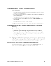
... the software. Intel® Compute Module MFS5000SI User Guide 45 Problems with Newly Installed Application Software Check the following : • Uninstall and reinstall the software. Ensure that might have occurred, reload the software and try running the software from a diskette, CD-ROM or DVD-ROM, try a different media. • Make sure the correct device drivers are Not Recognized within the Operating System Operating systems include a limited set of voltage spikes include a flickering video display, unexpected system reboots...
... the software. Intel® Compute Module MFS5000SI User Guide 45 Problems with Newly Installed Application Software Check the following : • Uninstall and reinstall the software. Ensure that might have occurred, reload the software and try running the software from a diskette, CD-ROM or DVD-ROM, try a different media. • Make sure the correct device drivers are Not Recognized within the Operating System Operating systems include a limited set of voltage spikes include a flickering video display, unexpected system reboots...
User Guide
Page 58
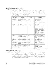
... the compute module that can aid in standby or sleeping mode Off = No Fault On = Critical error or nonrecoverable Slow blink = Non-critical Fast blink = Locate (when device does not have an ID LED) Double blink = Degraded state Use the Intel® Modular Server Control software to activate or inactivate the LED. Prior to system video initialization, if POST encounters a fatal system error, such as a processor problem, memory problem or video controller problem, the BIOS will trigger a series...
... the compute module that can aid in standby or sleeping mode Off = No Fault On = Critical error or nonrecoverable Slow blink = Non-critical Fast blink = Locate (when device does not have an ID LED) Double blink = Degraded state Use the Intel® Modular Server Control software to activate or inactivate the LED. Prior to system video initialization, if POST encounters a fatal system error, such as a processor problem, memory problem or video controller problem, the BIOS will trigger a series...
User Guide
Page 59
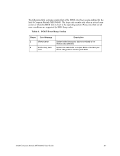
...; Compute Module MFS5000SI User Guide 47 The following table contains a partial list of the POST error beep codes enabled for the Intel® Compute Module MFS5000SI. The beep code sounds only when a critical error occurs or when the BIOS fails to boot to the last good BIOS. Table 3. Please note that not all error conditions are supported by BIOS beep codes. System has detected a corrupted BIOS in the flash part and is rolling back to the operating system. POST Error Beep Codes Beeps Error Message 3 Memory error 6 BIOS...
...; Compute Module MFS5000SI User Guide 47 The following table contains a partial list of the POST error beep codes enabled for the Intel® Compute Module MFS5000SI. The beep code sounds only when a critical error occurs or when the BIOS fails to boot to the last good BIOS. Table 3. Please note that not all error conditions are supported by BIOS beep codes. System has detected a corrupted BIOS in the flash part and is rolling back to the operating system. POST Error Beep Codes Beeps Error Message 3 Memory error 6 BIOS...

User Guide
Page 65
... instructions, misuse, neglect, alteration, repair, improper installation, or improper testing. In no event will have a reasonable time to make repairs or to replace Product or to refund the then-current value of any product soldered or otherwise permanently affixed to any other costs associated with other related charges. Current characterized errata are available upon request. Intel® Compute Module MFS5000SI User Guide 53 Software...
... instructions, misuse, neglect, alteration, repair, improper installation, or improper testing. In no event will have a reasonable time to make repairs or to replace Product or to refund the then-current value of any product soldered or otherwise permanently affixed to any other costs associated with other related charges. Current characterized errata are available upon request. Intel® Compute Module MFS5000SI User Guide 53 Software...
User Guide
Page 101
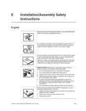
... the equipment and shall be easily accessible. Intel® Compute Module MFS5000SI User Guide 89 SAFETY STEPS: Whenever you can remove the system covers. Unplug all cables connected to I/O connectors or ports on the system does not turn off the system by wearing an antistatic wrist strap attached to the system. 2. Do not operate the system with more than one power supply will have completed the six...
... the equipment and shall be easily accessible. Intel® Compute Module MFS5000SI User Guide 89 SAFETY STEPS: Whenever you can remove the system covers. Unplug all cables connected to I/O connectors or ports on the system does not turn off the system by wearing an antistatic wrist strap attached to the system. 2. Do not operate the system with more than one power supply will have completed the six...


