
Smart Response Technology User Guide
Page 1
... SATA controller be set to RAID mode via the system BIOS. System Requirements: For a system to support Intel Smart Response Technology it must have the following: • Intel® Z68/Z77/H77/Q77 Express Chipset-based desktop board • Intel® Core™ Processor in the LGA1155 package • System BIOS with SATA mode set to RAID • Intel Rapid Storage Technology software 10.5 version release or later • Single Hard Disk Drive (HDD) or multiple HDD's in BIOS Setup 1. Go to enter the BIOS setup menu 2. Install the Intel Rapid Storage Technology software version...
... SATA controller be set to RAID mode via the system BIOS. System Requirements: For a system to support Intel Smart Response Technology it must have the following: • Intel® Z68/Z77/H77/Q77 Express Chipset-based desktop board • Intel® Core™ Processor in the LGA1155 package • System BIOS with SATA mode set to RAID • Intel Rapid Storage Technology software 10.5 version release or later • Single Hard Disk Drive (HDD) or multiple HDD's in BIOS Setup 1. Go to enter the BIOS setup menu 2. Install the Intel Rapid Storage Technology software version...

Technical Product Specification
Page 8
...3.5 Legacy USB Support 67 3.6 BIOS Updates 68 3.6.1 Language Support 68 3.6.2 Custom Splash Screen 69 3.7 BIOS Recovery 69 3.8 Boot Options 70 3.8.1 Optical Drive Boot 70 3.8.2 Network Boot 70 3.8.3 Booting Without Attached Devices 70 3.8.4 Changing the Default Boot Device During POST 70 3.9 Adjusting Boot Speed 71 3.9.1 Peripheral Selection and Configuration 71 3.9.2 BIOS Boot Optimizations 71 3.10 BIOS Security Features 72 3.11 BIOS Performance Features 73 4 Error Messages and Beep Codes 4.1 Speaker 75 4.2 BIOS Beep Codes 75 4.3 Front-panel Power LED Blink Codes 76 4.4 BIOS...
...3.5 Legacy USB Support 67 3.6 BIOS Updates 68 3.6.1 Language Support 68 3.6.2 Custom Splash Screen 69 3.7 BIOS Recovery 69 3.8 Boot Options 70 3.8.1 Optical Drive Boot 70 3.8.2 Network Boot 70 3.8.3 Booting Without Attached Devices 70 3.8.4 Changing the Default Boot Device During POST 70 3.9 Adjusting Boot Speed 71 3.9.1 Peripheral Selection and Configuration 71 3.9.2 BIOS Boot Optimizations 71 3.10 BIOS Security Features 72 3.11 BIOS Performance Features 73 4 Error Messages and Beep Codes 4.1 Speaker 75 4.2 BIOS Beep Codes 75 4.3 Front-panel Power LED Blink Codes 76 4.4 BIOS...
Technical Product Specification
Page 9
...SATA Connectors 49 15. Processor, Front and Rear Chassis, and Auxiliary (4-Pin) Fan Headers ..... 50 18. Front Panel Header 53 21. Connection Diagram for Front Panel USB Headers 55 14. Effects of Diagnostic LEDs 39 8. Memory Channel and DIMM Configuration 20 4. Connection Diagram for Front Panel Header 53 13. Feature Summary 11 2. Processor Core Power Connector 52 19. States for a One-Color Power LED 54 22. LAN Connector LED Locations 29 6. Component-side Connectors and Headers 47 12. Supported Memory Configurations 18 4. IEEE 1394a Header 49 13. Main...
...SATA Connectors 49 15. Processor, Front and Rear Chassis, and Auxiliary (4-Pin) Fan Headers ..... 50 18. Front Panel Header 53 21. Connection Diagram for Front Panel USB Headers 55 14. Effects of Diagnostic LEDs 39 8. Memory Channel and DIMM Configuration 20 4. Connection Diagram for Front Panel Header 53 13. Feature Summary 11 2. Processor Core Power Connector 52 19. States for a One-Color Power LED 54 22. LAN Connector LED Locations 29 6. Component-side Connectors and Headers 47 12. Supported Memory Configurations 18 4. IEEE 1394a Header 49 13. Main...
Technical Product Specification
Page 10
Front-panel Power LED Blink Codes 76 35. Supervisor and User Password Functions 72 33. Acceptable Drives/Media Types for Components 62 27. Boot Device Menu Options 70 32. BIOS Error Messages 76 36. Thermal Considerations for BIOS Recovery 69 31. Environmental Specifications 63 28. BIOS Beep Codes 75 34. Port 80h POST Codes 78 38. BIOS Setup Configuration Jumper Settings 57 24. Typical Port 80h POST Sequence 82 39. Regulatory Compliance Marks 91 x Recommended Power Supply Current Values 59 25. Safety Standards...
Front-panel Power LED Blink Codes 76 35. Supervisor and User Password Functions 72 33. Acceptable Drives/Media Types for Components 62 27. Boot Device Menu Options 70 32. BIOS Error Messages 76 36. Thermal Considerations for BIOS Recovery 69 31. Environmental Specifications 63 28. BIOS Beep Codes 75 34. Port 80h POST Codes 78 38. BIOS Setup Configuration Jumper Settings 57 24. Typical Port 80h POST Sequence 82 39. Regulatory Compliance Marks 91 x Recommended Power Supply Current Values 59 25. Safety Standards...
Technical Product Specification
Page 22
... SATA Drive Mode set to AHCI, you can install the operating system and the Intel Rapid Storage Technology driver. The Intel Z68 Express Chipset provides the USB controller for full-speed devices. The port arrangement is enabled, you must be set to RAID. Intel Desktop Board DZ68ZV Technical Product Specification NOTE The SATA Drive Mode must reinstall the operating system with the SATA Drive Mode set to RAID in the BIOS Setup in order for your system to use Intel Smart Response Technology. For information about The location of the front panel USB headers...
... SATA Drive Mode set to AHCI, you can install the operating system and the Intel Rapid Storage Technology driver. The Intel Z68 Express Chipset provides the USB controller for full-speed devices. The port arrangement is enabled, you must be set to RAID. Intel Desktop Board DZ68ZV Technical Product Specification NOTE The SATA Drive Mode must reinstall the operating system with the SATA Drive Mode set to RAID in the BIOS Setup in order for your system to use Intel Smart Response Technology. For information about The location of the front panel USB headers...
Technical Product Specification
Page 24
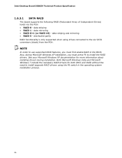
... the six SATA connectors (black) from the PCH. Intel Desktop Board DZ68ZV Technical Product Specification 1.6.3.1 SATA RAID The board supports the following RAID (Redundant Array of Independent Drives) levels via the PCH: • RAID 0 - data striping and mirroring • RAID 5 - Both Microsoft Windows Vista and Microsoft Windows 7 include the necessary RAID drivers for more information about installing drivers during Microsoft Windows XP installation, you must press F6 to use supported RAID features, you must first enable RAID in...
... the six SATA connectors (black) from the PCH. Intel Desktop Board DZ68ZV Technical Product Specification 1.6.3.1 SATA RAID The board supports the following RAID (Redundant Array of Independent Drives) levels via the PCH: • RAID 0 - data striping and mirroring • RAID 5 - Both Microsoft Windows Vista and Microsoft Windows 7 include the necessary RAID drivers for more information about installing drivers during Microsoft Windows XP installation, you must press F6 to use supported RAID features, you must first enable RAID in...
Technical Product Specification
Page 28
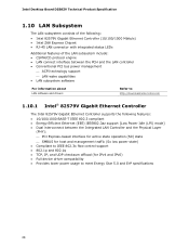
Intel Desktop Board DZ68ZV Technical Product Specification 1.10 LAN Subsystem The LAN subsystem consists of the following: • Intel 82579V Gigabit Ethernet Controller (10/100/1000 Mbits/s) • Intel Z68 Express Chipset • RJ-45 LAN connector with integrated status LEDs Additional features of the LAN subsystem include: • CSMA/CD protocol engine • LAN connect interface between the PCH and the LAN controller • Conventional PCI bus power management ⎯ ACPI technology support ⎯ LAN wake capabilities •...
Intel Desktop Board DZ68ZV Technical Product Specification 1.10 LAN Subsystem The LAN subsystem consists of the following: • Intel 82579V Gigabit Ethernet Controller (10/100/1000 Mbits/s) • Intel Z68 Express Chipset • RJ-45 LAN connector with integrated status LEDs Additional features of the LAN subsystem include: • CSMA/CD protocol engine • LAN connect interface between the PCH and the LAN controller • Conventional PCI bus power management ⎯ ACPI technology support ⎯ LAN wake capabilities •...
Technical Product Specification
Page 65
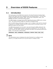
... BIOS Setup program, POST, the PCI auto-configuration utility, LAN EEPROM information, and Plug and Play support. The BIOS Setup program can be used to view and change the BIOS settings for the computer. The BIOS displays a message during POST identifying the type of BIOS Features 3.1 Introduction The board uses an Intel BIOS that is in the BIOS and reports if the two match. When the BIOS Setup configuration jumper is powered-up, the BIOS compares the CPU version and the microcode version in configure mode. The BIOS Setup...
... BIOS Setup program, POST, the PCI auto-configuration utility, LAN EEPROM information, and Plug and Play support. The BIOS Setup program can be used to view and change the BIOS settings for the computer. The BIOS displays a message during POST identifying the type of BIOS Features 3.1 Introduction The board uses an Intel BIOS that is in the BIOS and reports if the two match. When the BIOS Setup configuration jumper is powered-up, the BIOS compares the CPU version and the microcode version in configure mode. The BIOS Setup...
Technical Product Specification
Page 66
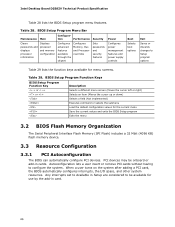
... cards. tion Performance Security Power Clears passwords and displays processor information Displays processor and memory configuration Configures advanced features available through the chipset Configures Memory, Bus and Processor overrides Sets passwords and security features Configures power management features and power supply controls Boot Selects boot options Exit Saves or discards changes to Setup program options Table 29 lists the function keys available for the current menu Save the current values and exits the BIOS Setup program Exits the menu 3.2 BIOS Flash Memory...
... cards. tion Performance Security Power Clears passwords and displays processor information Displays processor and memory configuration Configures advanced features available through the chipset Configures Memory, Bus and Processor overrides Sets passwords and security features Configures power management features and power supply controls Boot Selects boot options Exit Saves or discards changes to Setup program options Table 29 lists the function keys available for the current menu Save the current values and exits the BIOS Setup program Exits the menu 3.2 BIOS Flash Memory...
Technical Product Specification
Page 70
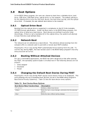
...drive, hard drive, USB drive, USB flash drive, optical drive, or the network. Boot Device Menu Options Boot Device Menu Function Keys or Description Selects a default boot device Exits the menu, saves changes, and boots from the LAN. Intel Desktop Board DZ68ZV Technical Product Specification 3.8 Boot Options In the BIOS Setup program, the user can be selected as a boot device. This menu displays the list of available boot devices (as set to Full. 3.8.3 Booting Without Attached Devices For use this key during POST causes a boot device menu to be the first boot device, the hard...
...drive, hard drive, USB drive, USB flash drive, optical drive, or the network. Boot Device Menu Options Boot Device Menu Function Keys or Description Selects a default boot device Exits the menu, saves changes, and boots from the LAN. Intel Desktop Board DZ68ZV Technical Product Specification 3.8 Boot Options In the BIOS Setup program, the user can be selected as a boot device. This menu displays the list of available boot devices (as set to Full. 3.8.3 Booting Without Attached Devices For use this key during POST causes a boot device menu to be the first boot device, the hard...
Technical Product Specification
Page 77
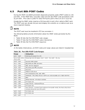
... Input devices: Keyboard/Mouse. 0xA0 - 0xAF For future use 0xF0 - 0xFF 77 Port 80h POST Code Ranges Range Subsystem 0x00 - 0x05 Entering SX states S0 to I /O Buses: PCI, USB, ATA etc. 0x5F is useful for determining the point where an error occurred. Not that critical since consoles should be installed in card, often called a POST card. Displaying the POST codes requires a PCI bus add-in PCI bus connector 1. This code is an unrecoverable error. S2...
... Input devices: Keyboard/Mouse. 0xA0 - 0xAF For future use 0xF0 - 0xFF 77 Port 80h POST Code Ranges Range Subsystem 0x00 - 0x05 Entering SX states S0 to I /O Buses: PCI, USB, ATA etc. 0x5F is useful for determining the point where an error occurred. Not that critical since consoles should be installed in card, often called a POST card. Displaying the POST codes requires a PCI bus add-in PCI bus connector 1. This code is an unrecoverable error. S2...
Product Guide for Intel Desktop Board DZ68ZV
Page 3
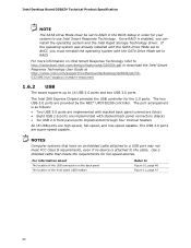
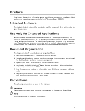
... components 3 Updating the BIOS: instructions on how to important information. may not be supported without further evaluation by Intel. NOTE Notes call attention to update the BIOS 4 Configuring for RAID Using Intel® Rapid Storage Technology: information about configuring your system for technically qualified personnel. Use Only for Intended Applications All Intel Desktop Boards are used in homes, offices, schools, computer rooms, and similar locations. Intended Audience The Product Guide is...
... components 3 Updating the BIOS: instructions on how to important information. may not be supported without further evaluation by Intel. NOTE Notes call attention to update the BIOS 4 Configuring for RAID Using Intel® Rapid Storage Technology: information about configuring your system for technically qualified personnel. Use Only for Intended Applications All Intel Desktop Boards are used in homes, offices, schools, computer rooms, and similar locations. Intended Audience The Product Guide is...
Product Guide for Intel Desktop Board DZ68ZV
Page 6
...Front Panel Power LED Header 51 Consumer IR (CIR) Headers 51 USB 2.0 Headers 52 Front Panel Header 53 Chassis Intrusion Header 53 Connecting to the Audio System 54 Connecting Chassis Fan and Power Supply Cables 55 Connecting Chassis Fan Cables 55 Connecting Power Supply Cables 56 Setting the BIOS Configuration Jumper 57 Clearing Passwords 58 Replacing the Battery 59 Installing the WiFi/Bluetooth Module in a Desktop Chassis (optional 65 3 Updating the BIOS Updating the BIOS with the Intel® Express BIOS Update Utility 67 Updating the BIOS Using the F7 Function Key 68 Updating...
...Front Panel Power LED Header 51 Consumer IR (CIR) Headers 51 USB 2.0 Headers 52 Front Panel Header 53 Chassis Intrusion Header 53 Connecting to the Audio System 54 Connecting Chassis Fan and Power Supply Cables 55 Connecting Chassis Fan Cables 55 Connecting Power Supply Cables 56 Setting the BIOS Configuration Jumper 57 Clearing Passwords 58 Replacing the Battery 59 Installing the WiFi/Bluetooth Module in a Desktop Chassis (optional 65 3 Updating the BIOS Updating the BIOS with the Intel® Express BIOS Update Utility 67 Updating the BIOS Using the F7 Function Key 68 Updating...
Product Guide for Intel Desktop Board DZ68ZV
Page 7
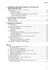
...and Reset Buttons 27 5. Intel Desktop Board DZ68ZV Mounting Screw Hole Locations 34 9. Connecting the Processor Fan Heat Sink Power Cable to BIOS Button 23 4. Installing the I/O Shield 33 8. Secure the Load Plate in Place 38 14. Location of the Processor and Voltage Regulator LEDs 28 6. Lift the Load Plate 36 11. Contents 4 Configuring Intel® Smart Response Technology and RAID Using Intel® RST Configuring Intel Smart Response Technology 71 Configuring RAID 72 Configuring the BIOS 72 Creating Your RAID Set 72 Loading the Intel RST RAID Drivers and Software...
...and Reset Buttons 27 5. Intel Desktop Board DZ68ZV Mounting Screw Hole Locations 34 9. Connecting the Processor Fan Heat Sink Power Cable to BIOS Button 23 4. Installing the I/O Shield 33 8. Secure the Load Plate in Place 38 14. Location of the Processor and Voltage Regulator LEDs 28 6. Lift the Load Plate 36 11. Contents 4 Configuring Intel® Smart Response Technology and RAID Using Intel® RST Configuring Intel Smart Response Technology 71 Configuring RAID 72 Configuring the BIOS 72 Creating Your RAID Set 72 Loading the Intel RST RAID Drivers and Software...
Product Guide for Intel Desktop Board DZ68ZV
Page 8
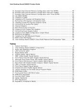
... 52 12. Jumper Settings for the BIOS Setup Program Modes 58 16. Port 80h POST Codes 77 20. Back Panel Audio Connectors 54 26. Removing a PCI Express x16 Graphics Card 46 22. Location of the BIOS Configuration Jumper Block 57 29. USB 2.0 Header Signal Names 52 13. Front-panel Power LED Blink Codes 75 18. Safety Standards 81 21. Feature Summary 9 2. Front Panel Header Signal Names 53 14. Installing a PCI Express x16 Graphics Card 45 21. Connecting the Serial ATA Cables 48 24. Example Dual Channel Memory Configuration with Three...
... 52 12. Jumper Settings for the BIOS Setup Program Modes 58 16. Port 80h POST Codes 77 20. Back Panel Audio Connectors 54 26. Removing a PCI Express x16 Graphics Card 46 22. Location of the BIOS Configuration Jumper Block 57 29. USB 2.0 Header Signal Names 52 13. Front-panel Power LED Blink Codes 75 18. Safety Standards 81 21. Feature Summary 9 2. Front Panel Header Signal Names 53 14. Installing a PCI Express x16 Graphics Card 45 21. Connecting the Serial ATA Cables 48 24. Example Dual Channel Memory Configuration with Three...
Product Guide for Intel Desktop Board DZ68ZV
Page 22
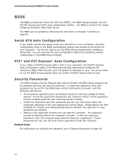
... changing depending on page 67. PCI* and PCI Express* Auto Configuration If you install a Serial ATA device (such as a hard drive) in your computer, the autoconfiguration utility in the BIOS automatically detects and configures the device for a password. If only the supervisor password is set, pressing at the password prompt of Setup gives the user restricted access to boot the computer. Intel Desktop Board DZ68ZV Product Guide BIOS The BIOS provides the Power-On Self-Test (POST), the BIOS Setup program, and the PCI/PCI Express and SATA auto-configuration utilities...
... changing depending on page 67. PCI* and PCI Express* Auto Configuration If you install a Serial ATA device (such as a hard drive) in your computer, the autoconfiguration utility in the BIOS automatically detects and configures the device for a password. If only the supervisor password is set, pressing at the password prompt of Setup gives the user restricted access to boot the computer. Intel Desktop Board DZ68ZV Product Guide BIOS The BIOS provides the Power-On Self-Test (POST), the BIOS Setup program, and the PCI/PCI Express and SATA auto-configuration utilities...
Product Guide for Intel Desktop Board DZ68ZV
Page 58
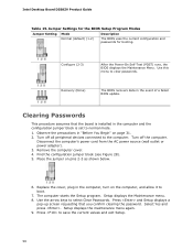
... devices connected to save the current values and exit Setup. 58 Find the configuration jumper block (see Figure 28). 5. Press and Setup displays a pop-up screen requesting that the board is installed in the event of a failed BIOS update. Use this menu to normal mode. 1. Clearing Passwords This procedure assumes that you confirm clearing the password. Turn off the computer. Select Yes and press . Place the jumper on page 31. 2. Intel Desktop Board DZ68ZV Product Guide...
... devices connected to save the current values and exit Setup. 58 Find the configuration jumper block (see Figure 28). 5. Press and Setup displays a pop-up screen requesting that the board is installed in the event of a failed BIOS update. Use this menu to normal mode. 1. Clearing Passwords This procedure assumes that you confirm clearing the password. Turn off the computer. Select Yes and press . Place the jumper on page 31. 2. Intel Desktop Board DZ68ZV Product Guide...
Product Guide for Intel Desktop Board DZ68ZV
Page 72
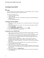
... installed respectively). Exit the Option ROM user interface by pressing after the Power-On-Self-Test (POST) memory tests begin. 3. Assemble your settings by pressing . Select Chipset SATA Mode and change the value to Create Volume. 8. Then save your system and attach two or more than the maximum volume size, you have selected the RAID LEVEL. 4. Press and enter the RAID Configuration Utility. 2. Intel Desktop Board DZ68ZV Product Guide Configuring RAID NOTE Intel RST RAID requires a Microsoft Windows...
... installed respectively). Exit the Option ROM user interface by pressing after the Power-On-Self-Test (POST) memory tests begin. 3. Assemble your settings by pressing . Select Chipset SATA Mode and change the value to Create Volume. 8. Then save your system and attach two or more than the maximum volume size, you have selected the RAID LEVEL. 4. Press and enter the RAID Configuration Utility. 2. Intel Desktop Board DZ68ZV Product Guide Configuring RAID NOTE Intel RST RAID requires a Microsoft Windows...
Product Guide for Intel Desktop Board DZ68ZV
Page 73
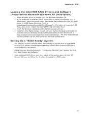
... the Intel RST RAID Drivers and Software." Follow the steps described above in a USB floppy disk drive. Updating the BIOS Loading the Intel RST RAID Drivers and Software (Required for information on supported USB floppy disk drives. Install the Intel® SATA RAID Controller driver. 3. Install the Intel Rapid Storage Console software via the Intel Express Installer CD included with your Desktop Board or after downloading it from the Windows installation CD. 2. Begin Windows Setup by booting from the Internet at http://support.intel.com/support/motherboards/desktop/. Setting Up...
... the Intel RST RAID Drivers and Software." Follow the steps described above in a USB floppy disk drive. Updating the BIOS Loading the Intel RST RAID Drivers and Software (Required for information on supported USB floppy disk drives. Install the Intel® SATA RAID Controller driver. 3. Install the Intel Rapid Storage Console software via the Intel Express Installer CD included with your Desktop Board or after downloading it from the Windows installation CD. 2. Begin Windows Setup by booting from the Internet at http://support.intel.com/support/motherboards/desktop/. Setting Up...
Product Guide for Intel Desktop Board DZ68ZV
Page 75
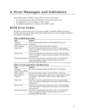
... and pause) until the system is powered off. A Error Messages and Indicators Intel Desktop Board DZ68ZV reports POST errors in progress Off when the update begins, then on the monitor • By displaying diagnostic progress codes (POST codes) BIOS Error Codes Whenever a recoverable error occurs during POST, the BIOS causes the board's speaker to beep and the front panel power LED to blink an error message indicating the problem (see Table 16). Video error On-off (0.5 seconds each ) three times...
... and pause) until the system is powered off. A Error Messages and Indicators Intel Desktop Board DZ68ZV reports POST errors in progress Off when the update begins, then on the monitor • By displaying diagnostic progress codes (POST codes) BIOS Error Codes Whenever a recoverable error occurs during POST, the BIOS causes the board's speaker to beep and the front panel power LED to blink an error message indicating the problem (see Table 16). Video error On-off (0.5 seconds each ) three times...


