
Product guide for Intel Desktop Board DZ68PL
Page 3
... Guide gives information about board layout, component installation, BIOS update, and regulatory requirements for technically qualified personnel. The suitability of product features 2 Installing and Replacing Desktop Board Components: instructions on how to install the Desktop Board and other hardware components 3 Updating the BIOS: instructions on how to update the BIOS 4 Configuring Intel Smart Response Technology and RAID Using Intel RST A Error Messages and Indicators: information about how to prevent damage to important information. iii may not be supported...
... Guide gives information about board layout, component installation, BIOS update, and regulatory requirements for technically qualified personnel. The suitability of product features 2 Installing and Replacing Desktop Board Components: instructions on how to install the Desktop Board and other hardware components 3 Updating the BIOS: instructions on how to update the BIOS 4 Configuring Intel Smart Response Technology and RAID Using Intel RST A Error Messages and Indicators: information about how to prevent damage to important information. iii may not be supported...
Product guide for Intel Desktop Board DZ68PL
Page 5
...14 Intel® Z68 Express Chipset 15 Intel® RST 15 Intel® RRT 15 Intel® Smart Response Technology 15 Main Memory...16 Graphics Support 17 Audio Subsystem 17 LAN Subsystem 18 USB Support ...19 SATA Support...19 Expandability...19 Legacy I/O ...20 BIOS ...20 SATA Auto Configuration 20 PCI*/PCI Express Auto Configuration 20 Security Passwords 21 Hardware Management 21 Hardware Monitoring and Fan Speed Control 21 Fan Monitoring 21 Chassis Intrusion 22 Power Management 22 Software Support 22 ACPI 22 Hardware Support 22 Power Connectors 22 Fan Headers 23 LAN Wake...
...14 Intel® Z68 Express Chipset 15 Intel® RST 15 Intel® RRT 15 Intel® Smart Response Technology 15 Main Memory...16 Graphics Support 17 Audio Subsystem 17 LAN Subsystem 18 USB Support ...19 SATA Support...19 Expandability...19 Legacy I/O ...20 BIOS ...20 SATA Auto Configuration 20 PCI*/PCI Express Auto Configuration 20 Security Passwords 21 Hardware Management 21 Hardware Monitoring and Fan Speed Control 21 Fan Monitoring 21 Chassis Intrusion 22 Power Management 22 Software Support 22 ACPI 22 Hardware Support 22 Power Connectors 22 Fan Headers 23 LAN Wake...
Product guide for Intel Desktop Board DZ68PL
Page 6
...40 Removing a PCI Express x16 Graphics Card 42 Connecting SATA Drives 43 Connecting to the Internal Headers 44 Front Panel Audio Header 45 IEEE 1394a Header 45 Chassis Intrusion Header 46 Consumer IR (CIR) Headers 46 Alternate Front Panel Power LED Header 47 Front Panel Header 47 Front Panel USB 2.0 Headers 48 S/PDIF Header 48 Connecting to the Audio System 49 Connecting Chassis Fan and Power Supply Cables 50 Connecting a Chassis Fan 50 Connecting Power Supply Cables 51 Setting the BIOS Configuration Jumper 52 Clearing Passwords 53 Replacing the Battery 54 3 Updating the BIOS...
...40 Removing a PCI Express x16 Graphics Card 42 Connecting SATA Drives 43 Connecting to the Internal Headers 44 Front Panel Audio Header 45 IEEE 1394a Header 45 Chassis Intrusion Header 46 Consumer IR (CIR) Headers 46 Alternate Front Panel Power LED Header 47 Front Panel Header 47 Front Panel USB 2.0 Headers 48 S/PDIF Header 48 Connecting to the Audio System 49 Connecting Chassis Fan and Power Supply Cables 50 Connecting a Chassis Fan 50 Connecting Power Supply Cables 51 Setting the BIOS Configuration Jumper 52 Clearing Passwords 53 Replacing the Battery 54 3 Updating the BIOS...
Product guide for Intel Desktop Board DZ68PL
Page 7
LAN Connector LEDs 18 3. Location of the Chassis Fan Header 50 23. Lift the Load Plate 32 8. Use DDR3 DIMMs 38 16. Installing a PCI Express x16 Graphics Card 41 18. Connecting a SATA Drive 43 20. Install the Processor 33 10. Example Dual Channel Memory Configuration with Three DIMMs 37 15. Example Dual Channel Memory Configuration with Four DIMMs 36 14. Internal Headers 44 21. Secure the Load Plate in Place 34 11. Installing a DIMM 39 17. Connecting Power Supply Cables 51 24. Unlatch the Socket Lever 31...
LAN Connector LEDs 18 3. Location of the Chassis Fan Header 50 23. Lift the Load Plate 32 8. Use DDR3 DIMMs 38 16. Installing a PCI Express x16 Graphics Card 41 18. Connecting a SATA Drive 43 20. Install the Processor 33 10. Example Dual Channel Memory Configuration with Three DIMMs 37 15. Example Dual Channel Memory Configuration with Four DIMMs 36 14. Internal Headers 44 21. Secure the Load Plate in Place 34 11. Installing a DIMM 39 17. Connecting Power Supply Cables 51 24. Unlatch the Socket Lever 31...
Product guide for Intel Desktop Board DZ68PL
Page 15
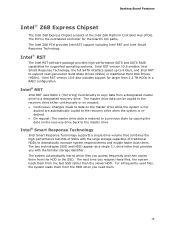
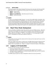
... Intel Smart Response Technology. For infrequently-used files, the system loads them from the fast SSD rather than 2.2 TB HDDs in a RAID configuration. Intel RST version 10.6 also includes support for larger than the slower HDD. The two technologies (SSD and HDD) appear as a single C:\ drive letter that combines the high-performance benefits of the Intel Z68 Platform Controller Hub (PCH). Intel® RST The Intel RST software package provides high-performance SATA and SATA RAID...
... Intel Smart Response Technology. For infrequently-used files, the system loads them from the fast SSD rather than 2.2 TB HDDs in a RAID configuration. Intel RST version 10.6 also includes support for larger than the slower HDD. The two technologies (SSD and HDD) appear as a single C:\ drive letter that combines the high-performance benefits of the Intel Z68 Platform Controller Hub (PCH). Intel® RST The Intel RST software package provides high-performance SATA and SATA RAID...
Product guide for Intel Desktop Board DZ68PL
Page 16
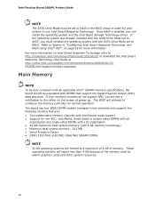
...://www.intel.com/support/motherboards/desktop/dz68db/sb/CS032499.htm?wapkw=(smart+response) Main Memory NOTE To be fully compliant with all applicable Intel ® SDRAM memory specifications, the board should be set to RAID in the BIOS Setup in two channels and supports the following memory features: • Two independent memory channels with interleaved mode support • Support for your memory modules do not support SPD, you can install the operating system and the Intel Rapid Storage Technology driver.
...://www.intel.com/support/motherboards/desktop/dz68db/sb/CS032499.htm?wapkw=(smart+response) Main Memory NOTE To be fully compliant with all applicable Intel ® SDRAM memory specifications, the board should be set to RAID in the BIOS Setup in two channels and supports the following memory features: • Two independent memory channels with interleaved mode support • Support for your memory modules do not support SPD, you can install the operating system and the Intel Rapid Storage Technology driver.
Product guide for Intel Desktop Board DZ68PL
Page 20
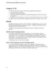
...IRQ support for PCI Conventional bus systems • Intelligent power management, including a programmable wake-up event interface The BIOS Setup program provides configuration options for the Legacy I /O space) for your computer, the PCI Express autoconfiguration utility in the BIOS automatically detects and configures the resources (IRQs, DMA channels, and I /O controller. Intel Desktop Board DZ68PL Product Guide Legacy I/O The board's Legacy I/O Controller provides the following the instructions in Chapter 3 starting on page 61. The BIOS can override the auto-configuration options by...
...IRQ support for PCI Conventional bus systems • Intelligent power management, including a programmable wake-up event interface The BIOS Setup program provides configuration options for the Legacy I /O space) for your computer, the PCI Express autoconfiguration utility in the BIOS automatically detects and configures the resources (IRQs, DMA channels, and I /O controller. Intel Desktop Board DZ68PL Product Guide Legacy I/O The board's Legacy I/O Controller provides the following the instructions in Chapter 3 starting on page 61. The BIOS can override the auto-configuration options by...
Product guide for Intel Desktop Board DZ68PL
Page 22
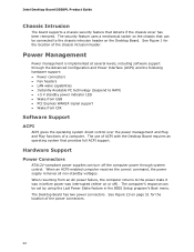
... Advanced Configuration and Power Interface (ACPI) and the following hardware support: • Power connectors • Fan headers • LAN wake capabilities • Instantly Available PC technology (Suspend to RAM) • +5 V standby power indicator LED • Wake from USB • PCI Express WAKE# signal support • Wake from an AC power failure, the computer returns to the chassis intrusion header on page 51 for the location of a computer. The Desktop Board has two power connectors. See Figure 23 on the Desktop Board. Intel Desktop Board DZ68PL Product Guide Chassis...
... Advanced Configuration and Power Interface (ACPI) and the following hardware support: • Power connectors • Fan headers • LAN wake capabilities • Instantly Available PC technology (Suspend to RAM) • +5 V standby power indicator LED • Wake from USB • PCI Express WAKE# signal support • Wake from an AC power failure, the computer returns to the chassis intrusion header on page 51 for the location of a computer. The Desktop Board has two power connectors. See Figure 23 on the Desktop Board. Intel Desktop Board DZ68PL Product Guide Chassis...

Product guide for Intel Desktop Board DZ68PL
Page 27
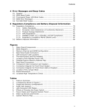
... as model, serial numbers, installed options, and configuration information. • Electrostatic discharge (ESD) can continue to the audio system • Connect chassis fan and power supply cables • Set the BIOS configuration jumper • Clear passwords • Replace the battery Before You Begin CAUTION The procedures in this chapter assume familiarity with the general terminology associated with personal computers and with the safety practices and regulatory compliance required for using an...
... as model, serial numbers, installed options, and configuration information. • Electrostatic discharge (ESD) can continue to the audio system • Connect chassis fan and power supply cables • Set the BIOS configuration jumper • Clear passwords • Replace the battery Before You Begin CAUTION The procedures in this chapter assume familiarity with the general terminology associated with personal computers and with the safety practices and regulatory compliance required for using an...
Product guide for Intel Desktop Board DZ68PL
Page 53
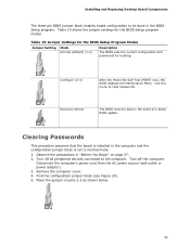
... the jumper settings for booting. Jumper Settings for the BIOS Setup Program Modes Jumper Setting Mode Normal (default) (1-2) Description The BIOS uses the current configuration and passwords for the BIOS Setup program modes. Turn off the computer. Place the jumper on page 27. 2. Observe the precautions in the BIOS Setup program. Turn off all peripheral devices connected to the computer. Configure (2-3) After the Power-On Self-Test (POST) runs, the BIOS displays the Maintenance Menu. Installing and Replacing Desktop Board Components The three-pin BIOS jumper block...
... the jumper settings for booting. Jumper Settings for the BIOS Setup Program Modes Jumper Setting Mode Normal (default) (1-2) Description The BIOS uses the current configuration and passwords for the BIOS Setup program modes. Turn off the computer. Place the jumper on page 27. 2. Observe the precautions in the BIOS Setup program. Turn off all peripheral devices connected to the computer. Configure (2-3) After the Power-On Self-Test (POST) runs, the BIOS displays the Maintenance Menu. Installing and Replacing Desktop Board Components The three-pin BIOS jumper block...
Product guide for Intel Desktop Board DZ68PL
Page 61
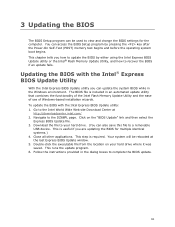
... hard drive. (You can also save this file to your hard drive where it was saved. This step is included in an automated update utility that combines the functionality of the Intel Flash Memory Update Utility and the ease of use of Windows-based installation wizards. This runs the update program. 6. Go to the Intel World Wide Web site Download Center at the last Express BIOS Update window. 5. Download the file to a removable USB device. 3 Updating the BIOS The BIOS Setup...
... hard drive. (You can also save this file to your hard drive where it was saved. This step is included in an automated update utility that combines the functionality of the Intel Flash Memory Update Utility and the ease of use of Windows-based installation wizards. This runs the update program. 6. Go to the Intel World Wide Web site Download Center at the last Express BIOS Update window. 5. Download the file to a removable USB device. 3 Updating the BIOS The BIOS Setup...
Product guide for Intel Desktop Board DZ68PL
Page 66
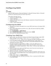
... Your RAID Set 1. Exit the Option ROM user interface by pressing or going to enter the RAID Configuration Utility. Press and enter the RAID Configuration Utility. 2. Intel Desktop Board DZ68PL Product Guide Configuring RAID NOTE Intel RST RAID requires a Microsoft Windows 7, Microsoft Windows Vista, or Microsoft Windows XP operating system and SATA hard drives. Assemble your settings by pressing after the Power-On-Self-Test (POST) memory tests begin. 3. Use the arrow keys to select RAID 0 or RAID 1 (if only two SATA drives are available), RAID 5 and RAID 10 (these options...
... Your RAID Set 1. Exit the Option ROM user interface by pressing or going to enter the RAID Configuration Utility. Press and enter the RAID Configuration Utility. 2. Intel Desktop Board DZ68PL Product Guide Configuring RAID NOTE Intel RST RAID requires a Microsoft Windows 7, Microsoft Windows Vista, or Microsoft Windows XP operating system and SATA hard drives. Assemble your settings by pressing after the Power-On-Self-Test (POST) memory tests begin. 3. Use the arrow keys to select RAID 0 or RAID 1 (if only two SATA drives are available), RAID 5 and RAID 10 (these options...

Product guide for Intel Desktop Board DZ68PL
Page 67
... system when a second SATA hard drive is added to upgrade from the Internet at http://support.intel.com/support/motherboards/desktop/. Finish the Windows installation and install all necessary drivers. 4. Follow the steps described above in a USB floppy disk drive. Install the Intel® SATA RAID Controller driver. 3. Configuring Intel Smart Response Technology and RAID Using Intel RST Loading the Intel RST RAID Drivers and Software (Required for information on supported USB floppy disk drives. The Intel Rapid Storage Console software can be used to a RAID setup. 67 Refer to...
... system when a second SATA hard drive is added to upgrade from the Internet at http://support.intel.com/support/motherboards/desktop/. Finish the Windows installation and install all necessary drivers. 4. Follow the steps described above in a USB floppy disk drive. Install the Intel® SATA RAID Controller driver. 3. Configuring Intel Smart Response Technology and RAID Using Intel RST Loading the Intel RST RAID Drivers and Software (Required for information on supported USB floppy disk drives. The Intel Rapid Storage Console software can be used to a RAID setup. 67 Refer to...
Technical product specification
Page 9
... Diagram 15 3. Thermal Sensors and Fan Headers 30 7. Connection Diagram for Front Panel Header 49 12. Board Dimensions 54 15. Components Shown in Figure 1 14 3. Back Panel Audio Connectors 26 5. LAN Connector LED Locations 28 6. Connection Diagram for Front Panel USB 2.0 Headers 51 13. Localized High Temperature Zones 57 Tables 1. Audio Jack Support 25 5. Back Panel Connectors 42 10. Supported Memory Configurations 19 4. Location of the Jumper Block 52 14. Power States and Targeted System Power 32 8. Wake-up Devices and Events 33 9. System Memory...
... Diagram 15 3. Thermal Sensors and Fan Headers 30 7. Connection Diagram for Front Panel Header 49 12. Board Dimensions 54 15. Components Shown in Figure 1 14 3. Back Panel Audio Connectors 26 5. LAN Connector LED Locations 28 6. Connection Diagram for Front Panel USB 2.0 Headers 51 13. Localized High Temperature Zones 57 Tables 1. Audio Jack Support 25 5. Back Panel Connectors 42 10. Supported Memory Configurations 19 4. Location of the Jumper Block 52 14. Power States and Targeted System Power 32 8. Wake-up Devices and Events 33 9. System Memory...
Technical product specification
Page 10
... Specifications 59 34. BIOS Setup Program Menu Bar 62 35. Port 80h POST Code Ranges 73 43. Typical Port 80h POST Sequence 78 45. States for Components 58 32. Fan Header Current Capability 56 31. Boot Device Menu Options 66 38. BIOS Beep Codes 71 40. Front-panel Power LED Blink Codes 72 41. BIOS Error Messages 72 42. EMC Regulations 83 47. Front Panel USB Headers 45 15. Chassis Intrusion Header 46 18. States for Components 58 33. BIOS Setup Configuration Jumper Settings...
... Specifications 59 34. BIOS Setup Program Menu Bar 62 35. Port 80h POST Code Ranges 73 43. Typical Port 80h POST Sequence 78 45. States for Components 58 32. Fan Header Current Capability 56 31. Boot Device Menu Options 66 38. BIOS Beep Codes 71 40. Front-panel Power LED Blink Codes 72 41. BIOS Error Messages 72 42. EMC Regulations 83 47. Front Panel USB Headers 45 15. Chassis Intrusion Header 46 18. States for Components 58 33. BIOS Setup Configuration Jumper Settings...
Technical product specification
Page 24
...Intel Desktop Board DZ68PL Technical Product Specification 1.7.1.1 SATA RAID The board supports Intel Rapid Storage Technology which provides the following features: • Consumer Infrared (CIR) headers • Serial IRQ interface compatible with an equivalent one. When the computer is plugged in CMOS RAM (for both AHCI and RAID without the need to install the RAID drivers. Replace the battery with serialized IRQ support for PCI systems • Intelligent power management, including a programmable wake-up event interface • PCI power management support The BIOS Setup...
...Intel Desktop Board DZ68PL Technical Product Specification 1.7.1.1 SATA RAID The board supports Intel Rapid Storage Technology which provides the following features: • Consumer Infrared (CIR) headers • Serial IRQ interface compatible with an equivalent one. When the computer is plugged in CMOS RAM (for both AHCI and RAID without the need to install the RAID drivers. Replace the battery with serialized IRQ support for PCI systems • Intelligent power management, including a programmable wake-up event interface • PCI power management support The BIOS Setup...
Technical product specification
Page 27
... Express Chipset • RJ-45 LAN connector with integrated status LEDs Additional features of the LAN subsystem include: • CSMA/CD protocol engine • LAN connect interface between the PCH and the LAN controller • PCI Conventional bus power management ACPI technology support LAN wake capabilities • LAN subsystem software For information about LAN software and drivers Refer to http://downloadcenter.intel.com 1.11.1 Intel® 82579V Gigabit Ethernet Controller The Intel 82579V Gigabit Ethernet Controller supports...
... Express Chipset • RJ-45 LAN connector with integrated status LEDs Additional features of the LAN subsystem include: • CSMA/CD protocol engine • LAN connect interface between the PCH and the LAN controller • PCI Conventional bus power management ACPI technology support LAN wake capabilities • LAN subsystem software For information about LAN software and drivers Refer to http://downloadcenter.intel.com 1.11.1 Intel® 82579V Gigabit Ethernet Controller The Intel 82579V Gigabit Ethernet Controller supports...
Technical product specification
Page 51
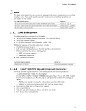
... display. Displaying the POST codes requires a POST card that conforms to I/O port 80h. Connection Diagram for determining the point where an error occurred. This code is useful for Front Panel USB 2.0 Headers 2.2.2.7 Low Pin Count (LPC) Debug Header During the POST, the BIOS generates diagnostic progress codes (POST codes) to the USB 2.0 specification for the front panel USB 2.0 headers. The POST card can interface with the Low Pin Count (LPC) Debug header. Technical Reference 2.2.2.6 Front Panel USB 2.0 Headers Figure 12 is a connection diagram for high-speed USB devices...
... display. Displaying the POST codes requires a POST card that conforms to I/O port 80h. Connection Diagram for determining the point where an error occurred. This code is useful for Front Panel USB 2.0 Headers 2.2.2.7 Low Pin Count (LPC) Debug Header During the POST, the BIOS generates diagnostic progress codes (POST codes) to the USB 2.0 specification for the front panel USB 2.0 headers. The POST card can interface with the Low Pin Count (LPC) Debug header. Technical Reference 2.2.2.6 Front Panel USB 2.0 Headers Figure 12 is a connection diagram for high-speed USB devices...
Technical product specification
Page 62
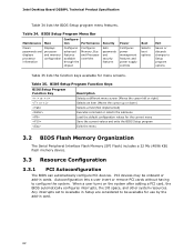
...passwords and displays processor information Displays processor and memory configuration Configures advanced features available through the chipset Configures Memory, Bus and Processor overrides Sets passwords and security features Power Configures power management features and power supply controls Boot Selects boot options Exit Saves or discards changes to be onboard or add-in Setup are considered to Setup program options Table 35 lists the function keys available for menu screens. PCI devices may be available for the current menu Save the current values and exits the BIOS...
...passwords and displays processor information Displays processor and memory configuration Configures advanced features available through the chipset Configures Memory, Bus and Processor overrides Sets passwords and security features Power Configures power management features and power supply controls Boot Selects boot options Exit Saves or discards changes to be onboard or add-in Setup are considered to Setup program options Table 35 lists the function keys available for menu screens. PCI devices may be available for the current menu Save the current values and exits the BIOS...
Technical product specification
Page 73
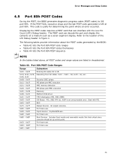
... MRC memory detection PEI phase post MRC execution Recovery 0x36 - 0x3F Platform DXE driver 0x41 - 0x4F CPU Initialization (PEI, DXE, SMM) 0x50 - 0x5F I /O port 80h. Start with the Low Pin Count (LPC) Debug header. If the POST fails, execution stops and the last POST code generated is useful for determining the point where an error occurred. S2, 0x30 - Refer to S5. Displaying the POST codes requires a POST card that...
... MRC memory detection PEI phase post MRC execution Recovery 0x36 - 0x3F Platform DXE driver 0x41 - 0x4F CPU Initialization (PEI, DXE, SMM) 0x50 - 0x5F I /O port 80h. Start with the Low Pin Count (LPC) Debug header. If the POST fails, execution stops and the last POST code generated is useful for determining the point where an error occurred. S2, 0x30 - Refer to S5. Displaying the POST codes requires a POST card that...


