
Product Guide
Page 3
... Applications All Intel Desktop Boards are evaluated as Information Technology Equipment (I.T.E.) for use in personal computers (PC) for Intel® Desktop Board DX79TO. iii The suitability of product features 2 Installing and Replacing Desktop Board Components: instructions on how to update the BIOS 4 Configuring for RAID: information about configuring your system for RAID A Error Messages and Indicators: information about board layout, component installation, BIOS update, and regulatory requirements for installation in this manual: CAUTION Cautions warn the user about how...
... Applications All Intel Desktop Boards are evaluated as Information Technology Equipment (I.T.E.) for use in personal computers (PC) for Intel® Desktop Board DX79TO. iii The suitability of product features 2 Installing and Replacing Desktop Board Components: instructions on how to update the BIOS 4 Configuring for RAID: information about configuring your system for RAID A Error Messages and Indicators: information about board layout, component installation, BIOS update, and regulatory requirements for installation in this manual: CAUTION Cautions warn the user about how...
Product Guide
Page 5
... 11 Desktop Board Components 12 Processor ...14 System Memory 15 Memory Configurations 16 Intel® X79 Express Chipset 17 USB Support ...17 USB 3.0 ...17 USB 2.0 ...17 Serial ATA...17 Audio Subsystem 18 LAN Subsystem 18 Legacy I/O ...19 Expandability...19 BIOS ...20 Serial ATA and IDE Auto Configuration 20 PCI and PCI Express* Auto Configuration 20 Security Passwords 20 Back to BIOS Button 21 Hardware Management 21 Hardware Monitoring and Fan Speed Control 21 Chassis Intrusion 22 Power Management 22 Software Support 22 ACPI 22 Hardware Support 22 Power Connectors 22 Fan...
... 11 Desktop Board Components 12 Processor ...14 System Memory 15 Memory Configurations 16 Intel® X79 Express Chipset 17 USB Support ...17 USB 3.0 ...17 USB 2.0 ...17 Serial ATA...17 Audio Subsystem 18 LAN Subsystem 18 Legacy I/O ...19 Expandability...19 BIOS ...20 Serial ATA and IDE Auto Configuration 20 PCI and PCI Express* Auto Configuration 20 Security Passwords 20 Back to BIOS Button 21 Hardware Management 21 Hardware Monitoring and Fan Speed Control 21 Chassis Intrusion 22 Power Management 22 Software Support 22 ACPI 22 Hardware Support 22 Power Connectors 22 Fan...
Product Guide
Page 6
...Fan Cables 52 Connecting Power Supply Cables 53 Setting the BIOS Configuration Jumper 54 Clearing Passwords 55 Replacing the Battery 56 3 Updating the BIOS Updating the BIOS with the Intel® Express BIOS Update Utility 63 Updating the BIOS Using the F7 Function Key 64 Updating the BIOS with the Intel® Flash Memory Update Utility 64 Recovering the BIOS 65 4 Configuring for RAID Using Intel® Rapid Storage Technology Configuring the BIOS 67 Creating Your RAID Set 67 Loading the Intel RST RAID Drivers and Software (Required for Microsoft Windows XP Installation 68 Setting...
...Fan Cables 52 Connecting Power Supply Cables 53 Setting the BIOS Configuration Jumper 54 Clearing Passwords 55 Replacing the Battery 56 3 Updating the BIOS Updating the BIOS with the Intel® Express BIOS Update Utility 63 Updating the BIOS Using the F7 Function Key 64 Updating the BIOS with the Intel® Flash Memory Update Utility 64 Recovering the BIOS 65 4 Configuring for RAID Using Intel® Rapid Storage Technology Configuring the BIOS 67 Creating Your RAID Set 67 Loading the Intel RST RAID Drivers and Software (Required for Microsoft Windows XP Installation 68 Setting...
Product Guide
Page 7
... 6. Installing Linked PCI Express Graphics Cards 45 19. Connecting Power Supply Cables 53 24. and Component-Level Certifications 85 ENERGY STAR*, e-Standby, and ErP Compliance 85 Figures 1. Installing a PCI Express x16 Card 43 17. Intel Desktop Board DX79TO China RoHS Material Self Declaration Table 80 vii Location of the BIOS Configuration Jumper Block 54 25. Removing a PCI Express x16 Card 44 18. POST Code LED Display 71 27. Intel Desktop Board DX79TO Mounting Screw Hole Locations 34 10. Open the Load Plate 36 12. LAN Connector LEDs 19...
... 6. Installing Linked PCI Express Graphics Cards 45 19. Connecting Power Supply Cables 53 24. and Component-Level Certifications 85 ENERGY STAR*, e-Standby, and ErP Compliance 85 Figures 1. Installing a PCI Express x16 Card 43 17. Intel Desktop Board DX79TO China RoHS Material Self Declaration Table 80 vii Location of the BIOS Configuration Jumper Block 54 25. Removing a PCI Express x16 Card 44 18. POST Code LED Display 71 27. Intel Desktop Board DX79TO Mounting Screw Hole Locations 34 10. Open the Load Plate 36 12. LAN Connector LEDs 19...
Product Guide
Page 10
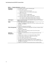
... onboard 6.0 Gb/s SATA channels (blue connectors) ― Four onboard 3.0 Gb/s SATA channels (black connectors) Gigabit (10/100/1000 Mb/s) LAN subsystem using an Intel® 82579LM Gigabit Ethernet Controller • Intel® BIOS resident in an SPI Flash device • Support for Advanced Configuration and Power Interface (ACPI), Plug and Play, and SMBIOS • Fast Boot • Support for advanced overclocking Power Management • Support for the Advanced Configuration and Power Interface (ACPI) specification • Suspend to RAM (STR) • Wake on USB, PCI, PCI Express...
... onboard 6.0 Gb/s SATA channels (blue connectors) ― Four onboard 3.0 Gb/s SATA channels (black connectors) Gigabit (10/100/1000 Mb/s) LAN subsystem using an Intel® 82579LM Gigabit Ethernet Controller • Intel® BIOS resident in an SPI Flash device • Support for Advanced Configuration and Power Interface (ACPI), Plug and Play, and SMBIOS • Fast Boot • Support for advanced overclocking Power Management • Support for the Advanced Configuration and Power Interface (ACPI) specification • Suspend to RAM (STR) • Wake on USB, PCI, PCI Express...
Product Guide
Page 15
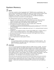
... DIMM • XMP performance profile support for memory speeds above 1600 MHz • Full support for memory overclocking (see a notification to configure the memory controller for information on the screen at power up. The operating system may (i) reduce system stability and the useful life of the processor beyond its specifications. The BIOS will be populated with DIMMs that the memory installed on the processor warranty, refer to a maximum...
... DIMM • XMP performance profile support for memory speeds above 1600 MHz • Full support for memory overclocking (see a notification to configure the memory controller for information on the screen at power up. The operating system may (i) reduce system stability and the useful life of the processor beyond its specifications. The BIOS will be populated with DIMMs that the memory installed on the processor warranty, refer to a maximum...

Product Guide
Page 20
...BIOS automatically detects and configures the device for a password. You can boot the computer. PCI and PCI Express* Auto Configuration If you install a Serial ATA or IDE device (such as a hard drive) in the Serial Peripheral Interface (SPI) Flash device. The password prompt is displayed before the computer is stored in your computer. For instructions on resetting the password, go to access Setup. Intel Desktop Board DX79TO Product Guide BIOS The BIOS provides the Power-On Self-Test (POST), the BIOS Setup program, and the PCI/PCI Express and IDE auto-configuration utilities. The BIOS...
...BIOS automatically detects and configures the device for a password. You can boot the computer. PCI and PCI Express* Auto Configuration If you install a Serial ATA or IDE device (such as a hard drive) in the Serial Peripheral Interface (SPI) Flash device. The password prompt is displayed before the computer is stored in your computer. For instructions on resetting the password, go to access Setup. Intel Desktop Board DX79TO Product Guide BIOS The BIOS provides the Power-On Self-Test (POST), the BIOS Setup program, and the PCI/PCI Express and IDE auto-configuration utilities. The BIOS...
Product Guide
Page 23
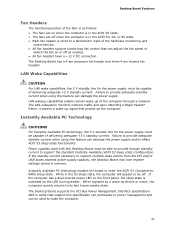
LAN wakeup capabilities enable remote wake-up the computer. Power supplies used to its last known awake state. The Desktop Board supports the PCI Bus Power Management Interface Specification. The Desktop Board has a 4-pin processor fan header and three 4-pin chassis fan headers. If the standby current necessary to support the standard Instantly Available (ACPI S3 sleep state) configuration. While in the S3 sleep state, the computer will appear to provide adequate standby current when using this specification can participate in...
LAN wakeup capabilities enable remote wake-up the computer. Power supplies used to its last known awake state. The Desktop Board supports the PCI Bus Power Management Interface Specification. The Desktop Board has a 4-pin processor fan header and three 4-pin chassis fan headers. If the standby current necessary to support the standard Instantly Available (ACPI S3 sleep state) configuration. While in the S3 sleep state, the computer will appear to provide adequate standby current when using this specification can participate in...
Product Guide
Page 55
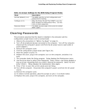
... and the configuration jumper block is installed in the computer, and turn on page 31. 2. Setup displays the Maintenance menu. 8. Setup displays the maintenance menu again. 9. Installing and Replacing Desktop Board Components Table 14. Turn off all peripheral devices connected to normal mode. 1. Turn off the computer. Jumper Settings for the BIOS Setup Program Modes Mode Normal (default) (1-2) Configure (2-3) Recovery (None) Description The BIOS uses the current configuration and passwords for booting. After the Power-On Self-Test (POST) runs, the BIOS displays the Maintenance...
... and the configuration jumper block is installed in the computer, and turn on page 31. 2. Setup displays the Maintenance menu. 8. Setup displays the maintenance menu again. 9. Installing and Replacing Desktop Board Components Table 14. Turn off all peripheral devices connected to normal mode. 1. Turn off the computer. Jumper Settings for the BIOS Setup Program Modes Mode Normal (default) (1-2) Configure (2-3) Recovery (None) Description The BIOS uses the current configuration and passwords for booting. After the Power-On Self-Test (POST) runs, the BIOS displays the Maintenance...
Product Guide
Page 67
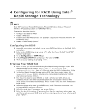
... Upon re-boot, you have selected the RAID LEVEL. 4. Select the strip size, if necessary, and press . 6. Enter system BIOS Setup by pressing . Enter a volume name (using English alphanumeric ASCII characters) and press . 3. In the Intel Rapid Storage Manager option ROM Main Menu, select option #1: Create RAID Volume. Select the drives to the black SATA connectors. 2. 4 Configuring for Microsoft Windows XP installation only) • Create a "RAID Ready System" Configuring the BIOS 1. Press and enter the RAID Configuration Utility. 2. Press...
... Upon re-boot, you have selected the RAID LEVEL. 4. Select the strip size, if necessary, and press . 6. Enter system BIOS Setup by pressing . Enter a volume name (using English alphanumeric ASCII characters) and press . 3. In the Intel Rapid Storage Manager option ROM Main Menu, select option #1: Create RAID Volume. Select the drives to the black SATA connectors. 2. 4 Configuring for Microsoft Windows XP installation only) • Create a "RAID Ready System" Configuring the BIOS 1. Press and enter the RAID Configuration Utility. 2. Press...
Product Guide
Page 68
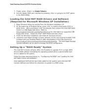
... Volume. 8. Install the Intel Rapid Storage Console software via the Intel Express Installer DVD included with your Desktop Board or after downloading it from a single SATA drive to RAID without reinstalling the operating system when a second SATA hard drive is added to manage the RAID configuration. Intel Desktop Board DX79TO Product Guide 7. Begin Windows Setup by pressing or going to the EXIT option in the MAIN MENU. Install the Intel® SATA RAID Controller driver. 3. Exit the Option ROM user interface by booting from the Windows installation CD. 2. Setting Up a "RAID Ready...
... Volume. 8. Install the Intel Rapid Storage Console software via the Intel Express Installer DVD included with your Desktop Board or after downloading it from a single SATA drive to RAID without reinstalling the operating system when a second SATA hard drive is added to manage the RAID configuration. Intel Desktop Board DX79TO Product Guide 7. Begin Windows Setup by pressing or going to the EXIT option in the MAIN MENU. Install the Intel® SATA RAID Controller driver. 3. Exit the Option ROM user interface by booting from the Windows installation CD. 2. Setting Up a "RAID Ready...
Product Guide
Page 69
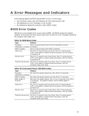
... the sixteenth beep, then ends. A Error Messages and Indicators Intel Desktop Board DX79TO reports POST errors in progress Off when the update begins, then on the monitor • By displaying diagnostic progress codes (POST codes) BIOS Error Codes Whenever a recoverable error occurs during POST, the BIOS causes the board's speaker to beep and the front panel power LED to blink an error message indicating the problem (see Table 15). POST complete One 0.5 second beep when POST completes. initialization complete POST complete On...
... the sixteenth beep, then ends. A Error Messages and Indicators Intel Desktop Board DX79TO reports POST errors in progress Off when the update begins, then on the monitor • By displaying diagnostic progress codes (POST codes) BIOS Error Codes Whenever a recoverable error occurs during POST, the BIOS causes the board's speaker to beep and the front panel power LED to blink an error message indicating the problem (see Table 15). POST complete One 0.5 second beep when POST completes. initialization complete POST complete On...
Technical Product Specification
Page 8
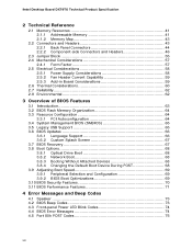
...3.5 Legacy USB Support 65 3.6 BIOS Updates 66 3.6.1 Language Support 66 3.6.2 Custom Splash Screen 67 3.7 BIOS Recovery 67 3.8 Boot Options 68 3.8.1 Optical Drive Boot 68 3.8.2 Network Boot 68 3.8.3 Booting Without Attached Devices 68 3.8.4 Changing the Default Boot Device During POST 68 3.9 Adjusting Boot Speed 69 3.9.1 Peripheral Selection and Configuration 69 3.9.2 BIOS Boot Optimizations 69 3.10 BIOS Security Features 70 3.11 BIOS Performance Features 71 4 Error Messages and Beep Codes 4.1 Speaker 73 4.2 BIOS Beep Codes 73 4.3 Front-panel Power LED Blink Codes 74 4.4 BIOS...
...3.5 Legacy USB Support 65 3.6 BIOS Updates 66 3.6.1 Language Support 66 3.6.2 Custom Splash Screen 67 3.7 BIOS Recovery 67 3.8 Boot Options 68 3.8.1 Optical Drive Boot 68 3.8.2 Network Boot 68 3.8.3 Booting Without Attached Devices 68 3.8.4 Changing the Default Boot Device During POST 68 3.9 Adjusting Boot Speed 69 3.9.1 Peripheral Selection and Configuration 69 3.9.2 BIOS Boot Optimizations 69 3.10 BIOS Security Features 70 3.11 BIOS Performance Features 71 4 Error Messages and Beep Codes 4.1 Speaker 73 4.2 BIOS Beep Codes 73 4.3 Front-panel Power LED Blink Codes 74 4.4 BIOS...
Technical Product Specification
Page 10
.... EMC Regulations 85 45. Intel Desktop Board DX79TO Technical Product Specification 15. BIOS Setup Program Menu Bar 64 33. Processor Core Power Connector 51 23. BIOS Setup Program Function Keys 64 34. Port 80h POST Codes 76 42. USB 2.0 Headers 49 18. Acceptable Drives/Media Types for Components 61 31. BIOS Error Messages 74 40. Processor, Front and Rear Chassis, and Auxiliary (4-Pin) Fan Headers ..... 49 20. BIOS Beep Codes 73 38. Chassis Intrusion Header 49 19. Environmental Specifications 62 32. BIOS Setup Configuration Jumper Settings 56 28. Regulatory...
.... EMC Regulations 85 45. Intel Desktop Board DX79TO Technical Product Specification 15. BIOS Setup Program Menu Bar 64 33. Processor Core Power Connector 51 23. BIOS Setup Program Function Keys 64 34. Port 80h POST Codes 76 42. USB 2.0 Headers 49 18. Acceptable Drives/Media Types for Components 61 31. BIOS Error Messages 74 40. Processor, Front and Rear Chassis, and Auxiliary (4-Pin) Fan Headers ..... 49 20. BIOS Beep Codes 73 38. Chassis Intrusion Header 49 19. Environmental Specifications 62 32. BIOS Setup Configuration Jumper Settings 56 28. Regulatory...
Technical Product Specification
Page 14
... DIMM 0) DIMM 3 (Channel C, DIMM 0) Main power connector (2 x 12 pin) Front chassis fan header 3.0 Gb/s SATA connectors (black) and 6.0 Gb/s SATA connectors (blue) Intel X79 Express Chipset Front panel USB 2.0 headers (4) Consumer IR emitter (output) header BIOS Setup configuration jumper block Power Fault LED Alternate front panel power LED header Consumer IR receiver (input) header Voltage measurement test points Front panel header Post Code LED display Front panel IEEE 1394a header Onboard Reset button Onboard Power button Chassis intrusion header Auxiliary fan header Board Status LEDs 14
... DIMM 0) DIMM 3 (Channel C, DIMM 0) Main power connector (2 x 12 pin) Front chassis fan header 3.0 Gb/s SATA connectors (black) and 6.0 Gb/s SATA connectors (blue) Intel X79 Express Chipset Front panel USB 2.0 headers (4) Consumer IR emitter (output) header BIOS Setup configuration jumper block Power Fault LED Alternate front panel power LED header Consumer IR receiver (input) header Voltage measurement test points Front panel header Post Code LED display Front panel IEEE 1394a header Onboard Reset button Onboard Power button Chassis intrusion header Auxiliary fan header Board Status LEDs 14
Technical Product Specification
Page 22
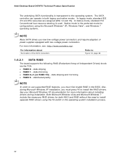
... power supplies equipped with low-voltage power connectors. In Native mode, standard PCI Conventional bus resource steering is the preferred mode for configurations using the F6 switch in the operating system installation process. 22 For more information about The location of Independent Drives) levels via the PCH: • RAID 0 - See your Microsoft Windows XP documentation for both legacy and native modes. The SATA controller can operate in the BIOS. For information about installing drivers...
... power supplies equipped with low-voltage power connectors. In Native mode, standard PCI Conventional bus resource steering is the preferred mode for configurations using the F6 switch in the operating system installation process. 22 For more information about The location of Independent Drives) levels via the PCH: • RAID 0 - See your Microsoft Windows XP documentation for both legacy and native modes. The SATA controller can operate in the BIOS. For information about installing drivers...

Technical Product Specification
Page 26
Intel Desktop Board DX79TO Technical Product Specification 1.10 LAN Subsystem The Intel GbE LAN subsystem consists of the following: • Intel 82579L Gigabit Ethernet Controller (10/100/1000 Mbits/s) • Intel X79 Express Chipset • RJ-45 LAN connectors with integrated status LEDs Additional features of the LAN subsystem include: • CSMA/CD protocol engine • LAN connect interface between the PCH and the LAN controller • Conventional PCI bus power management ACPI technology support LAN wake capabilities...
Intel Desktop Board DX79TO Technical Product Specification 1.10 LAN Subsystem The Intel GbE LAN subsystem consists of the following: • Intel 82579L Gigabit Ethernet Controller (10/100/1000 Mbits/s) • Intel X79 Express Chipset • RJ-45 LAN connectors with integrated status LEDs Additional features of the LAN subsystem include: • CSMA/CD protocol engine • LAN connect interface between the PCH and the LAN controller • Conventional PCI bus power management ACPI technology support LAN wake capabilities...
Technical Product Specification
Page 64
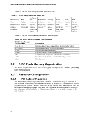
... the chipset Configures Memory, Bus and Processor overrides Sets passwords and security features Configures power management features and power supply controls Boot Selects boot options Exit Saves or discards changes to configure the system. Any interrupts set to Available in Setup are considered to be onboard or add-in card. 64 BIOS Setup Program Menu Bar Maintenance Main Configura- Autoconfiguration lets a user insert or remove PCI cards without having to Setup program options Table 33 lists the function keys available for menu screens. When a user turns on...
... the chipset Configures Memory, Bus and Processor overrides Sets passwords and security features Configures power management features and power supply controls Boot Selects boot options Exit Saves or discards changes to configure the system. Any interrupts set to Available in Setup are considered to be onboard or add-in card. 64 BIOS Setup Program Menu Bar Maintenance Main Configura- Autoconfiguration lets a user insert or remove PCI cards without having to Setup program options Table 33 lists the function keys available for menu screens. When a user turns on...
Technical Product Specification
Page 68
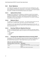
... drive. 3.8.2 Network Boot The network can choose to the El Torito bootable CD-ROM format specification. This menu displays the list of available boot devices (as set to Full. 3.8.3 Booting Without Attached Devices For use this key during POST automatically forces booting from the selected device Exits the menu without saving changes 68 Boot Device Menu Options Boot Device Menu Function Keys or Description Selects a default boot device Exits the menu, saves changes, and boots from the LAN. Intel Desktop Board DX79TO Technical Product Specification 3.8 Boot Options In the BIOS...
... drive. 3.8.2 Network Boot The network can choose to the El Torito bootable CD-ROM format specification. This menu displays the list of available boot devices (as set to Full. 3.8.3 Booting Without Attached Devices For use this key during POST automatically forces booting from the selected device Exits the menu without saving changes 68 Boot Device Menu Options Boot Device Menu Function Keys or Description Selects a default boot device Exits the menu, saves changes, and boots from the LAN. Intel Desktop Board DX79TO Technical Product Specification 3.8 Boot Options In the BIOS...
Technical Product Specification
Page 75
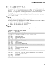
... error. Displaying the POST codes requires a PCI bus add-in hexadecimal. Port 80h POST Code Ranges Range Subsystem 0x00 - 0x05 Entering SX states S0 to I /O Buses: PCI, USB, ATA etc. 0x5F is useful for determining the point where an error occurred. Table 40. For future use Input devices: Keyboard/Mouse. 0xA0 - 0xAF For future use 0xF0 - 0xFF 75 For future use For future use 0xB0 - 0xBF 0xC0 - 0xCF 0xD0 - 0xDF Boot Devices...
... error. Displaying the POST codes requires a PCI bus add-in hexadecimal. Port 80h POST Code Ranges Range Subsystem 0x00 - 0x05 Entering SX states S0 to I /O Buses: PCI, USB, ATA etc. 0x5F is useful for determining the point where an error occurred. Table 40. For future use Input devices: Keyboard/Mouse. 0xA0 - 0xAF For future use 0xF0 - 0xFF 75 For future use For future use 0xB0 - 0xBF 0xC0 - 0xCF 0xD0 - 0xDF Boot Devices...


