
Product Specification
Page 8
Intel Desktop Board DX79SR Technical Product Specification 1.13 Power Management 32 1.13.1 ACPI 32 1.13.2 Hardware Support 35 1.14 Board Status LEDs 39 1.15 Onboard Power and Reset Buttons 41 2 Technical Reference 2.1 Memory Resources 43 2.1.1 Addressable Memory 43 2.1.2 Memory Map 45 2.2 Connectors and Headers 45 2.2.1 Back Panel Connectors 46 2.2.2 Component-side Connectors and Headers 48 2.3 Jumper Block 58 2.4 Mechanical Considerations 60 2.4.1 Form Factor 60 2.5 Electrical Considerations 61 2.5.1 Power Supply Considerations 61 2.5.2 Fan Header Current Capability 62 2.5.3 ...
Intel Desktop Board DX79SR Technical Product Specification 1.13 Power Management 32 1.13.1 ACPI 32 1.13.2 Hardware Support 35 1.14 Board Status LEDs 39 1.15 Onboard Power and Reset Buttons 41 2 Technical Reference 2.1 Memory Resources 43 2.1.1 Addressable Memory 43 2.1.2 Memory Map 45 2.2 Connectors and Headers 45 2.2.1 Back Panel Connectors 46 2.2.2 Component-side Connectors and Headers 48 2.3 Jumper Block 58 2.4 Mechanical Considerations 60 2.4.1 Form Factor 60 2.5 Electrical Considerations 61 2.5.1 Power Supply Considerations 61 2.5.2 Fan Header Current Capability 62 2.5.3 ...
Product Specification
Page 9
...3. Supported Memory Configurations 18 4. LAN Connector LED Locations 27 6. Thermal Sensors and Fan Headers 31 8. Board Dimensions 60 18. Feature Summary 11 2. Memory Channel and DIMM Configuration 20 4. LAN Connector LED States 27 6. I/O Shield Reference Diagram 47 13. Connection Diagram for Front Panel USB 2.0 Headers 57 16. Detailed System Memory Address Map 44 11. Back Panel Audio Connectors 25 5. Major Board Components 13 2. Contents 4 Error Messages and Beep Codes 4.1 Speaker 77 4.2 BIOS Beep Codes 77 4.3 Front-panel Power LED Blink Codes...
...3. Supported Memory Configurations 18 4. LAN Connector LED Locations 27 6. Thermal Sensors and Fan Headers 31 8. Board Dimensions 60 18. Feature Summary 11 2. Memory Channel and DIMM Configuration 20 4. LAN Connector LED States 27 6. I/O Shield Reference Diagram 47 13. Connection Diagram for Front Panel USB 2.0 Headers 57 16. Detailed System Memory Address Map 44 11. Back Panel Audio Connectors 25 5. Major Board Components 13 2. Contents 4 Error Messages and Beep Codes 4.1 Speaker 77 4.2 BIOS Beep Codes 77 4.3 Front-panel Power LED Blink Codes...
Product Specification
Page 10
.... Port 80h POST Codes 80 41. States for a Two-Color Power LED 56 26. EMC Regulations 89 44. BIOS Beep Codes 77 37. States for a One-Color Power LED 56 25. Thermal Considerations for Intel HD Audio 50 13. System Memory Map 45 11. Front Panel Audio Header for Components 64 30. Component-side Connectors and Headers Shown in Figure 13 49 12. Intel Desktop Board DX79SR Technical Product Specification 8. Boot Device Menu Options 72 35. BIOS Error Messages...
.... Port 80h POST Codes 80 41. States for a Two-Color Power LED 56 26. EMC Regulations 89 44. BIOS Beep Codes 77 37. States for a One-Color Power LED 56 25. Thermal Considerations for Intel HD Audio 50 13. System Memory Map 45 11. Front Panel Audio Header for Components 64 30. Component-side Connectors and Headers Shown in Figure 13 49 12. Intel Desktop Board DX79SR Technical Product Specification 8. Boot Device Menu Options 72 35. BIOS Error Messages...
Product Specification
Page 12
...Advanced Configuration and Power Interface (ACPI), Plug and Play, and SMBIOS • Fast Boot • Support for advanced over clocking Instantly Available • Support for PCI* Local Bus Specification Revision 2.3 PC Technology • Support for PCI Express* Revision 3.0 • Suspend to RAM support • Wake on PCI, PCI Express, LAN, front panel, CIR, and USB ports LAN Support Dual-Gigabit (10/100/1000 Mbits/s) LAN subsystem using the Intel® 82579L and Intel® 82574L Gigabit Ethernet Controllers Expansion Capabilities • Two PCI Express 3.0 x16 connectors...
...Advanced Configuration and Power Interface (ACPI), Plug and Play, and SMBIOS • Fast Boot • Support for advanced over clocking Instantly Available • Support for PCI* Local Bus Specification Revision 2.3 PC Technology • Support for PCI Express* Revision 3.0 • Suspend to RAM support • Wake on PCI, PCI Express, LAN, front panel, CIR, and USB ports LAN Support Dual-Gigabit (10/100/1000 Mbits/s) LAN subsystem using the Intel® 82579L and Intel® 82574L Gigabit Ethernet Controllers Expansion Capabilities • Two PCI Express 3.0 x16 connectors...

Product Specification
Page 14
.../s connectors through the PCH (black) SATA 6.0 Gb/s connectors through a Marvell 88SE9128 controller (gray) Intel X79 Express Chipset Front panel USB 2.0 headers (4) Consumer IR emitter (output) header BIOS Setup configuration jumper block Power Fault LED Front panel USB 3.0 connector Alternate front panel power LED header Consumer IR receiver (input) header Voltage measurement test points Front panel header Post Code LED display Front panel IEEE 1394a header Onboard Reset button Onboard Power button Chassis intrusion header Auxiliary fan header Board Status LEDs 14 Intel Desktop Board DX79SR...
.../s connectors through the PCH (black) SATA 6.0 Gb/s connectors through a Marvell 88SE9128 controller (gray) Intel X79 Express Chipset Front panel USB 2.0 headers (4) Consumer IR emitter (output) header BIOS Setup configuration jumper block Power Fault LED Front panel USB 3.0 connector Alternate front panel power LED header Consumer IR receiver (input) header Voltage measurement test points Front panel header Post Code LED display Front panel IEEE 1394a header Onboard Reset button Onboard Power button Chassis intrusion header Auxiliary fan header Board Status LEDs 14 Intel Desktop Board DX79SR...
Product Specification
Page 16
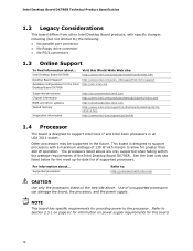
...Intel Desktop Board DX79SR Technical Product Specification 1.2 Legacy Considerations This board differs from other Intel Desktop Board products, with specific changes including (but not limited to) the following: • No parallel port connector • No floppy drive connector • No PS/2 connectors 1.3 Online Support To find information about ... Other processors may be supported in an LGA 2011 socket. Supported processors Refer to: http://processormatch.intel.com CAUTION Use only the processors listed on power supply requirements for the Intel Desktop Board DX79SR...
...Intel Desktop Board DX79SR Technical Product Specification 1.2 Legacy Considerations This board differs from other Intel Desktop Board products, with specific changes including (but not limited to) the following: • No parallel port connector • No floppy drive connector • No PS/2 connectors 1.3 Online Support To find information about ... Other processors may be supported in an LGA 2011 socket. Supported processors Refer to: http://processormatch.intel.com CAUTION Use only the processors listed on power supply requirements for the Intel Desktop Board DX79SR...
Product Specification
Page 17
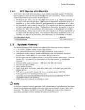
...; XMP performance profile support for memory speeds above 1600 MHz • Full support for over clocking memory (see www.intel.com/support/motherboards/desktop/sb/CS-031689.htm for more information about PCI Express technology Refer to http://www.pcisig.com 1.5 System Memory The board has eight DIMM sockets and supports the following memory features: • 1.35 V DDR3 SDRAM DIMMs (JEDEC Specification) • Four independent memory channels with interleaved mode support • Unbuffered...
...; XMP performance profile support for memory speeds above 1600 MHz • Full support for over clocking memory (see www.intel.com/support/motherboards/desktop/sb/CS-031689.htm for more information about PCI Express technology Refer to http://www.pcisig.com 1.5 System Memory The board has eight DIMM sockets and supports the following memory features: • 1.35 V DDR3 SDRAM DIMMs (JEDEC Specification) • Four independent memory channels with interleaved mode support • Unbuffered...
Product Specification
Page 18
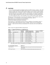
... operation of SDRAM) and "SS" refers to : http://support.intel.com/support/motherboards/desktop/sb/CS025414.htm http://www.intel.com/personal/gaming/extremememory.htm 18 Table 3 lists the supported DIMM configurations. For information about... For information on the desktop board, if used with the memory manufacturer for DDR3 memory voltage. Intel Desktop Board DX79SR Technical Product Specification CAUTION 1.5 V is the recommended and default setting for warranty terms and additional details. Table 3.
... operation of SDRAM) and "SS" refers to : http://support.intel.com/support/motherboards/desktop/sb/CS025414.htm http://www.intel.com/personal/gaming/extremememory.htm 18 Table 3 lists the supported DIMM configurations. For information about... For information on the desktop board, if used with the memory manufacturer for DDR3 memory voltage. Intel Desktop Board DX79SR Technical Product Specification CAUTION 1.5 V is the recommended and default setting for warranty terms and additional details. Table 3.
Product Specification
Page 22
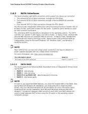
Intel Desktop Board DX79SR Technical Product Specification 1.6.2 SATA Interfaces The board provides eight SATA connectors which support one device per connector: • Two internal SATA 6.0 Gb/s connectors through the PCH (blue) • Two internal SATA 6.0 Gb/s connectors through a Marvell 88SE9128 controller (gray) • Four internal SATA 3.0 Gb/s connectors through the PCH (black) The PCH provides independent SATA ports with low-voltage power connectors. In legacy mode, standard IDE I/O and IRQ resources are assigned (IRQ 14 and 15). For information about installing drivers ...
Intel Desktop Board DX79SR Technical Product Specification 1.6.2 SATA Interfaces The board provides eight SATA connectors which support one device per connector: • Two internal SATA 6.0 Gb/s connectors through the PCH (blue) • Two internal SATA 6.0 Gb/s connectors through a Marvell 88SE9128 controller (gray) • Four internal SATA 3.0 Gb/s connectors through the PCH (black) The PCH provides independent SATA ports with low-voltage power connectors. In legacy mode, standard IDE I/O and IRQ resources are assigned (IRQ 14 and 15). For information about installing drivers ...
Product Specification
Page 26
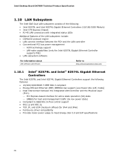
... Specification 1.10 LAN Subsystem The Intel GbE Dual LAN subsystem consists of the following: • Intel 82579L and Intel 82574L Gigabit Ethernet Controllers (10/100/1000 Mbits/s) • Intel X79 Express Chipset • RJ-45 LAN connectors with integrated status LEDs Additional features of the LAN subsystem include: • CSMA/CD protocol engine • LAN connect interface between the PCH and the LAN controller • Conventional PCI bus power management ⎯ ACPI technology support ⎯ LAN wake...
... Specification 1.10 LAN Subsystem The Intel GbE Dual LAN subsystem consists of the following: • Intel 82579L and Intel 82574L Gigabit Ethernet Controllers (10/100/1000 Mbits/s) • Intel X79 Express Chipset • RJ-45 LAN connectors with integrated status LEDs Additional features of the LAN subsystem include: • CSMA/CD protocol engine • LAN connect interface between the PCH and the LAN controller • Conventional PCI bus power management ⎯ ACPI technology support ⎯ LAN wake...

Product Specification
Page 32
... an ACPI-aware driver), video displays, and hard disk drives • Methods for achieving less than six seconds ...the system enters this state Power-on how ACPI is configured with this state... Off (ACPI G2/G5 - Intel Desktop Board DX79SR Technical Product Specification 1.13 Power Management Power management is implemented at http://www.acpi.info/) • Support for multiple wake-up events (see Table 8 on page 34) • Support for a front panel power and sleep mode switch Table 6 lists...
... an ACPI-aware driver), video displays, and hard disk drives • Methods for achieving less than six seconds ...the system enters this state Power-on how ACPI is configured with this state... Off (ACPI G2/G5 - Intel Desktop Board DX79SR Technical Product Specification 1.13 Power Management Power management is implemented at http://www.acpi.info/) • Support for multiple wake-up events (see Table 8 on page 34) • Support for a front panel power and sleep mode switch Table 6 lists...
Product Specification
Page 39
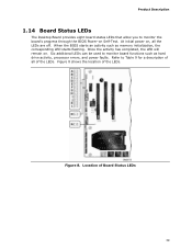
... . Once the activity has completed, the LED will remain on , all of the LEDs. Product Description 1.14 Board Status LEDs The Desktop Board provides eight board status LEDs that allow you to monitor board functions such as memory initialization, the corresponding LED starts flashing. Figure 8 shows the location of Board Status LEDs 39 When the BIOS starts an activity such as hard drive activity, processor errors, and power faults. Refer to Table 9 for a description...
... . Once the activity has completed, the LED will remain on , all of the LEDs. Product Description 1.14 Board Status LEDs The Desktop Board provides eight board status LEDs that allow you to monitor board functions such as memory initialization, the corresponding LED starts flashing. Figure 8 shows the location of Board Status LEDs 39 When the BIOS starts an activity such as hard drive activity, processor errors, and power faults. Refer to Table 9 for a description...
Product Specification
Page 67
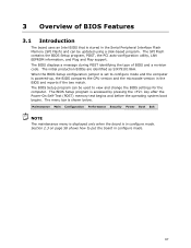
... PCI auto-configuration utility, LAN EEPROM information, and Plug and Play support. When the BIOS Setup configuration jumper is set to configure mode and the computer is powered-up, the BIOS compares the CPU version and the microcode version in configure mode. The initial production BIOSs are identified as SIX7910J.86A. The menu bar is accessed by pressing the key after the Power-On Self-Test (POST) memory test begins and before the operating system boot begins. Maintenance Main Configuration...
... PCI auto-configuration utility, LAN EEPROM information, and Plug and Play support. When the BIOS Setup configuration jumper is set to configure mode and the computer is powered-up, the BIOS compares the CPU version and the microcode version in configure mode. The initial production BIOSs are identified as SIX7910J.86A. The menu bar is accessed by pressing the key after the Power-On Self-Test (POST) memory test begins and before the operating system boot begins. Maintenance Main Configuration...
Product Specification
Page 68
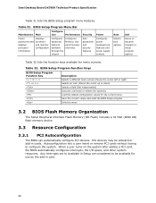
Intel Desktop Board DX79SR Technical Product Specification Table 31 lists the BIOS Setup program menu features. Autoconfiguration lets a user insert or remove PCI cards without having to Setup program options Table 32 lists the function keys available for use by the add-in cards. Any interrupts set to Available in Setup are considered to be onboard or add-in card. 68 tion Performance Security Power Clears passwords and displays processor information Displays processor and memory configuration Configures advanced features available through the chipset Configures Memory, Bus ...
Intel Desktop Board DX79SR Technical Product Specification Table 31 lists the BIOS Setup program menu features. Autoconfiguration lets a user insert or remove PCI cards without having to Setup program options Table 32 lists the function keys available for use by the add-in cards. Any interrupts set to Available in Setup are considered to be onboard or add-in card. 68 tion Performance Security Power Clears passwords and displays processor information Displays processor and memory configuration Configures advanced features available through the chipset Configures Memory, Bus ...
Product Specification
Page 69
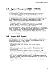
..., legacy support is used to Enabled. By default, Legacy USB support is loading, USB keyboards and mice are not recognized during this information. The operating system loads. While the operating system is set to enter and configure the BIOS Setup program and the maintenance menu. 4. The BIOS enables applications such as third-party management software to use a USB keyboard to Disabled in the BIOS under the Additional Information header under the Main BIOS page. 3.5 Legacy USB Support Legacy USB support enables USB devices to be used to access the BIOS Setup program...
..., legacy support is used to Enabled. By default, Legacy USB support is loading, USB keyboards and mice are not recognized during this information. The operating system loads. While the operating system is set to enter and configure the BIOS Setup program and the maintenance menu. 4. The BIOS enables applications such as third-party management software to use a USB keyboard to Disabled in the BIOS under the Additional Information header under the Main BIOS page. 3.5 Legacy USB Support Legacy USB support enables USB devices to be used to access the BIOS Setup program...
Product Specification
Page 72
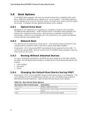
... 34. Intel Desktop Board DX79SR Technical Product Specification 3.8 Boot Options In the BIOS Setup program, the user can be set to Full. 3.8.3 Booting Without Attached Devices For use this key during POST, the User Access Level in the BIOS Setup program's Security menu must be selected as set in priority order. This selection allows booting from a diskette drive, hard drive, USB drive, USB flash drive, optical drive, or the network. This menu displays the list of available boot devices (as a boot device. Boot devices are not present: • Video adapter • Keyboard...
... 34. Intel Desktop Board DX79SR Technical Product Specification 3.8 Boot Options In the BIOS Setup program, the user can be set to Full. 3.8.3 Booting Without Attached Devices For use this key during POST, the User Access Level in the BIOS Setup program's Security menu must be selected as set in priority order. This selection allows booting from a diskette drive, hard drive, USB drive, USB flash drive, optical drive, or the network. This menu displays the list of available boot devices (as a boot device. Boot devices are not present: • Video adapter • Keyboard...
Product Specification
Page 73
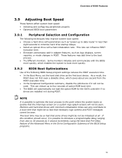
... features, such as logo displays, screen repaints, or mode changes in the Drive Configuration Submenu of the BIOS Setup program). 73 Some monitors initialize and communicate with the BIOS more quickly. 3.9.2 BIOS Boot Optimizations Use of the following techniques help improve system boot speed: • Choose a hard drive with parameters such as "power-up to four seconds of option ROM boot time. • The BIOS will not be used. NOTE It is possible...
... features, such as logo displays, screen repaints, or mode changes in the Drive Configuration Submenu of the BIOS Setup program). 73 Some monitors initialize and communicate with the BIOS more quickly. 3.9.2 BIOS Boot Optimizations Use of the following techniques help improve system boot speed: • Choose a hard drive with parameters such as "power-up to four seconds of option ROM boot time. • The BIOS will not be used. NOTE It is possible...
Product Specification
Page 74
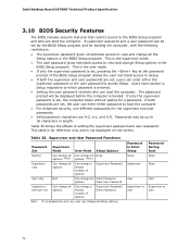
... 0-9. Supervisor and User Password Functions Password Set Supervisor Mode User Mode Setup Options Neither Can change all Can change all None options (Note) options (Note) Supervisor only Can change all the Setup options in length. The password prompt will be up to 16 characters in the BIOS Setup program. Intel Desktop Board DX79SR Technical Product Specification 3.10 BIOS Security Features The BIOS includes security features that restrict access to the BIOS Setup program and who can boot the computer. If...
... 0-9. Supervisor and User Password Functions Password Set Supervisor Mode User Mode Setup Options Neither Can change all Can change all None options (Note) options (Note) Supervisor only Can change all the Setup options in length. The password prompt will be up to 16 characters in the BIOS Setup program. Intel Desktop Board DX79SR Technical Product Specification 3.10 BIOS Security Features The BIOS includes security features that restrict access to the BIOS Setup program and who can boot the computer. If...
Product Specification
Page 78
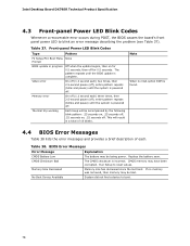
.... If no VGA option ROM is powered off . Memory Size Decreased Memory size has decreased since the last boot. This will be bad. Thermal trip warning Each beep will result in progress Off when the update begins, then on , .25 seconds off . Intel Desktop Board DX79SR Technical Product Specification 4.3 Front-panel Power LED Blink Codes Whenever a recoverable error occurs during POST, the BIOS causes the board's front panel power LED to blink an error message describing the problem (see...
.... If no VGA option ROM is powered off . Memory Size Decreased Memory size has decreased since the last boot. This will be bad. Thermal trip warning Each beep will result in progress Off when the update begins, then on , .25 seconds off . Intel Desktop Board DX79SR Technical Product Specification 4.3 Front-panel Power LED Blink Codes Whenever a recoverable error occurs during POST, the BIOS causes the board's front panel power LED to blink an error message describing the problem (see...

Product Specification
Page 79
This code is an unrecoverable error. Displaying the POST codes requires a PCI bus add-in PCI bus connector 1. NOTE The POST card must be up at port 80h. S2, 0x30 - Security (SEC) phase PEI phase pre MRC execution MRC memory detection PEI phase post MRC execution Recovery Platform DXE driver 0x41 - 0x4F 0x50 - 0x5F 0x60 - 0x6F CPU Initialization (PEI, DXE, SMM) I /O port 80h. The POST card can decode the port and display the contents...
This code is an unrecoverable error. Displaying the POST codes requires a PCI bus add-in PCI bus connector 1. NOTE The POST card must be up at port 80h. S2, 0x30 - Security (SEC) phase PEI phase pre MRC execution MRC memory detection PEI phase post MRC execution Recovery Platform DXE driver 0x41 - 0x4F 0x50 - 0x5F 0x60 - 0x6F CPU Initialization (PEI, DXE, SMM) I /O port 80h. The POST card can decode the port and display the contents...


