
Product Specification
Page 2
... these for future definition and shall have patents or pending patent applications, trademarks, copyrights, or other intellectual property rights. Contact your local Intel sales office or your distributor to only the standard Intel® Desktop Board DX79SR with BIOS identifier SIX7910J.86A. All rights reserved. INFORMATION IN THIS DOCUMENT IS PROVIDED IN CONNECTION WITH...
... these for future definition and shall have patents or pending patent applications, trademarks, copyrights, or other intellectual property rights. Contact your local Intel sales office or your distributor to only the standard Intel® Desktop Board DX79SR with BIOS identifier SIX7910J.86A. All rights reserved. INFORMATION IN THIS DOCUMENT IS PROVIDED IN CONNECTION WITH...
Product Specification
Page 3
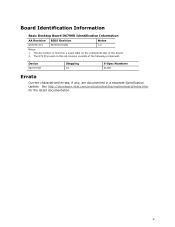
See http://developer.intel.com/products/desktop/motherboard/index.htm for the latest documentation. iii The AA number is found on a small label on this AA revision consists of the board. 2. The X79 PCH used on the component side of the following component: Device 82X79 PCH Stepping C1 S-Spec Numbers SLJN7 Errata Current characterized errata, if any, are documented in a separate Specification Update. Board Identification Information Basic Desktop Board DX79SR Identification Information AA Revision BIOS Revision Notes G57199-201 SIX7910J.0281 1,2 Notes: 1.
See http://developer.intel.com/products/desktop/motherboard/index.htm for the latest documentation. iii The AA number is found on a small label on this AA revision consists of the board. 2. The X79 PCH used on the component side of the following component: Device 82X79 PCH Stepping C1 S-Spec Numbers SLJN7 Errata Current characterized errata, if any, are documented in a separate Specification Update. Board Identification Information Basic Desktop Board DX79SR Identification Information AA Revision BIOS Revision Notes G57199-201 SIX7910J.0281 1,2 Notes: 1.
Product Specification
Page 5
... this level of information. Preface This Technical Product Specification (TPS) specifies the board layout, components, connectors, power and environmental requirements, and the BIOS for the Intel® Desktop Board DX79SR. Intended Audience The TPS is specifically not intended for general audiences. CAUTION Cautions are included to important information. It is intended to the...
... this level of information. Preface This Technical Product Specification (TPS) specifies the board layout, components, connectors, power and environmental requirements, and the BIOS for the Intel® Desktop Board DX79SR. Intended Audience The TPS is specifically not intended for general audiences. CAUTION Cautions are included to important information. It is intended to the...
Product Specification
Page 8
Intel Desktop Board DX79SR Technical Product Specification 1.13 Power Management 32 1.13.1 ACPI 32 1.13.2 Hardware Support 35 1.14 Board Status LEDs 39 1.15 Onboard ... Considerations 63 2.7 Reliability 65 2.8 Environmental 65 3 Overview of BIOS Features 3.1 Introduction 67 3.2 BIOS Flash Memory Organization 68 3.3 Resource Configuration 68 3.3.1 PCI Autoconfiguration 68 3.4 System Management BIOS (SMBIOS 69 3.5 Legacy USB Support 69 3.6 BIOS Updates 70 3.6.1 Language Support 70 3.6.2 Custom Splash Screen 71 3.7 BIOS Recovery 71 3.8 Boot Options 72 3.8.1 Optical Drive Boot 72 ...
Intel Desktop Board DX79SR Technical Product Specification 1.13 Power Management 32 1.13.1 ACPI 32 1.13.2 Hardware Support 35 1.14 Board Status LEDs 39 1.15 Onboard ... Considerations 63 2.7 Reliability 65 2.8 Environmental 65 3 Overview of BIOS Features 3.1 Introduction 67 3.2 BIOS Flash Memory Organization 68 3.3 Resource Configuration 68 3.3.1 PCI Autoconfiguration 68 3.4 System Management BIOS (SMBIOS 69 3.5 Legacy USB Support 69 3.6 BIOS Updates 70 3.6.1 Language Support 70 3.6.2 Custom Splash Screen 71 3.7 BIOS Recovery 71 3.8 Boot Options 72 3.8.1 Optical Drive Boot 72 ...
Product Specification
Page 9
... Status LEDs 39 9. Connection Diagram for Front Panel USB 2.0 Headers 57 16. Contents 4 Error Messages and Beep Codes 4.1 Speaker 77 4.2 BIOS Beep Codes 77 4.3 Front-panel Power LED Blink Codes 78 4.4 BIOS Error Messages 78 4.5 Port 80h POST Codes 79 5 Regulatory Compliance and Battery Disposal Information 5.1 Regulatory Compliance 85 5.1.1 Safety Standards 85...
... Status LEDs 39 9. Connection Diagram for Front Panel USB 2.0 Headers 57 16. Contents 4 Error Messages and Beep Codes 4.1 Speaker 77 4.2 BIOS Beep Codes 77 4.3 Front-panel Power LED Blink Codes 78 4.4 BIOS Error Messages 78 4.5 Port 80h POST Codes 79 5 Regulatory Compliance and Battery Disposal Information 5.1 Regulatory Compliance 85 5.1.1 Safety Standards 85...
Product Specification
Page 10
...User Password Functions 74 36. Port 80h POST Code Ranges 79 40. States for Intel HD Audio 50 13. Fan Header Current Capability 62 29. BIOS Setup Program Function Keys 68 33. Safety Standards 85 43. Front Panel Audio Header...in Figure 13 49 12. Chassis Intrusion Header 52 20. Main Power Connector 54 23. Thermal Considerations for BIOS Recovery 71 34. System Memory Map 45 11. Acceptable Drives/Media Types for Components 64 30. Front-...31. Wake-up Devices and Events 34 9. Board Status LEDs 40 10. Intel Desktop Board DX79SR Technical Product Specification 8.
...User Password Functions 74 36. Port 80h POST Code Ranges 79 40. States for Intel HD Audio 50 13. Fan Header Current Capability 62 29. BIOS Setup Program Function Keys 68 33. Safety Standards 85 43. Front Panel Audio Header...in Figure 13 49 12. Chassis Intrusion Header 52 20. Main Power Connector 54 23. Thermal Considerations for BIOS Recovery 71 34. System Memory Map 45 11. Acceptable Drives/Media Types for Components 64 30. Front-...31. Wake-up Devices and Events 34 9. Board Status LEDs 40 10. Intel Desktop Board DX79SR Technical Product Specification 8.
Product Specification
Page 12
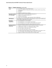
Feature Summary (continued) BIOS • Intel® BIOS resident in the SPI Flash device • Support for Advanced ... panel, CIR, and USB ports LAN Support Dual-Gigabit (10/100/1000 Mbits/s) LAN subsystem using the Intel® 82579L and Intel® 82574L Gigabit Ethernet Controllers Expansion Capabilities • Two PCI Express 3.0 x16 connectors • One PCI..., front, rear, and auxiliary) with selectable support in BIOS for 3 wire fans • Support for Platform Environmental Control Interface (PECI) 12 Intel Desktop Board DX79SR Technical Product Specification Table 1.
Feature Summary (continued) BIOS • Intel® BIOS resident in the SPI Flash device • Support for Advanced ... panel, CIR, and USB ports LAN Support Dual-Gigabit (10/100/1000 Mbits/s) LAN subsystem using the Intel® 82579L and Intel® 82574L Gigabit Ethernet Controllers Expansion Capabilities • Two PCI Express 3.0 x16 connectors • One PCI..., front, rear, and auxiliary) with selectable support in BIOS for 3 wire fans • Support for Platform Environmental Control Interface (PECI) 12 Intel Desktop Board DX79SR Technical Product Specification Table 1.

Product Specification
Page 14
Intel Desktop Board DX79SR Technical Product Specification Table 2. Components Shown in Figure 1 Label A B C D E F G H I J K L M N O P Q R S T U V W X Y Z AA BB CC DD EE FF GG HH II JJ KK LL MM NN OO PP ... through the PCH (blue) SATA 3.0 Gb/s connectors through the PCH (black) SATA 6.0 Gb/s connectors through a Marvell 88SE9128 controller (gray) Intel X79 Express Chipset Front panel USB 2.0 headers (4) Consumer IR emitter (output) header BIOS Setup configuration jumper block Power Fault LED Front panel USB 3.0 connector Alternate front panel power LED header Consumer IR...
Intel Desktop Board DX79SR Technical Product Specification Table 2. Components Shown in Figure 1 Label A B C D E F G H I J K L M N O P Q R S T U V W X Y Z AA BB CC DD EE FF GG HH II JJ KK LL MM NN OO PP ... through the PCH (blue) SATA 3.0 Gb/s connectors through the PCH (black) SATA 6.0 Gb/s connectors through a Marvell 88SE9128 controller (gray) Intel X79 Express Chipset Front panel USB 2.0 headers (4) Consumer IR emitter (output) header BIOS Setup configuration jumper block Power Fault LED Front panel USB 3.0 connector Alternate front panel power LED header Consumer IR...
Product Specification
Page 16
...intel.com Supported processors Chipset information BIOS and driver updates Tested memory Integration information http://processormatch.intel.com http://www.intel.com/products/desktop/chipsets/index.htm http://downloadcenter.intel.com http://www.intel.com/support/motherboards/desktop/sb/CS025414.htm http://www.intel... • No PS/2 connectors 1.3 Online Support To find information about ... Intel Desktop Board DX79SR Technical Product Specification 1.2 Legacy Considerations This board differs from other Intel Desktop Board products, with margin to allow for the most up-to Section ...
...intel.com Supported processors Chipset information BIOS and driver updates Tested memory Integration information http://processormatch.intel.com http://www.intel.com/products/desktop/chipsets/index.htm http://downloadcenter.intel.com http://www.intel.com/support/motherboards/desktop/sb/CS025414.htm http://www.intel... • No PS/2 connectors 1.3 Online Support To find information about ... Intel Desktop Board DX79SR Technical Product Specification 1.2 Legacy Considerations This board differs from other Intel Desktop Board products, with margin to allow for the most up-to Section ...
Product Specification
Page 17
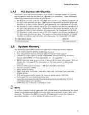
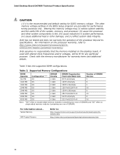
...MHz SDRAM DIMMs • XMP performance profile support for memory speeds above 1600 MHz • Full support for over clocking memory (see www.intel.com/support/motherboards/desktop/sb/CS-031689.htm for more information about PCI Express technology Refer to http://www.pcisig.com 1.5 System Memory The...The maximum theoretical bandwidth of the x16 interface is 4 GB/s in graphics cards via the board's PCI Express x16 connectors. This allows the BIOS to read the SPD data and program the chipset to Section 2.1.1 on page 43 for information on the total amount of addressable memory. •...
...MHz SDRAM DIMMs • XMP performance profile support for memory speeds above 1600 MHz • Full support for over clocking memory (see www.intel.com/support/motherboards/desktop/sb/CS-031689.htm for more information about PCI Express technology Refer to http://www.pcisig.com 1.5 System Memory The...The maximum theoretical bandwidth of the x16 interface is 4 GB/s in graphics cards via the board's PCI Express x16 connectors. This allows the BIOS to read the SPD data and program the chipset to Section 2.1.1 on page 43 for information on the total amount of addressable memory. •...
Product Specification
Page 18
Intel has not tested and does not warranty the operation of SDRAM) and "SS" refers to fail; (iii) cause reductions in the BIOS Setup program are provided for any particular purpose. For information on the desktop board, if used with the memory ... M x8/512 M x8 16 Note: "DS" refers to double-sided memory modules (containing two rows of the processor beyond its specifications. Intel Desktop Board DX79SR Technical Product Specification CAUTION 1.5 V is the recommended and default setting for warranty terms and additional details. Check with altered clock frequencies and/or...
Intel has not tested and does not warranty the operation of SDRAM) and "SS" refers to fail; (iii) cause reductions in the BIOS Setup program are provided for any particular purpose. For information on the desktop board, if used with the memory ... M x8/512 M x8 16 Note: "DS" refers to double-sided memory modules (containing two rows of the processor beyond its specifications. Intel Desktop Board DX79SR Technical Product Specification CAUTION 1.5 V is the recommended and default setting for warranty terms and additional details. Check with altered clock frequencies and/or...
Product Specification
Page 22
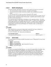
... operating system installation process. 22 In Native mode, standard PCI Conventional bus resource steering is used . distributed parity NOTE In order to device connections. Intel Desktop Board DX79SR Technical Product Specification 1.6.2 SATA Interfaces The board provides eight SATA connectors which support one device per connector: • Two internal SATA 6.0 Gb/s connectors ... SATA RAID The board supports the following RAID (Redundant Array of 6.0 Gb/s for four ports and 3.0 Gb/s for configurations using the F6 switch in the BIOS. data mirroring • RAID 0+1 (or RAID 10) -
... operating system installation process. 22 In Native mode, standard PCI Conventional bus resource steering is used . distributed parity NOTE In order to device connections. Intel Desktop Board DX79SR Technical Product Specification 1.6.2 SATA Interfaces The board provides eight SATA connectors which support one device per connector: • Two internal SATA 6.0 Gb/s connectors ... SATA RAID The board supports the following RAID (Redundant Array of 6.0 Gb/s for four ports and 3.0 Gb/s for configurations using the F6 switch in the BIOS. data mirroring • RAID 0+1 (or RAID 10) -
Product Specification
Page 23
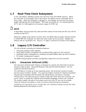
...VSB applied via the power supply 5V STBY rail. The clock is made up event interface • PCI power management support The BIOS Setup program provides configuration options for this feature to control external electronic hardware. This learning input is designed to ± 13 ... header consists of other user remotes. Figure 1 on page 13 shows the location of three years. When the computer is not plugged into Intel Desktop Boards for the I /O controller provides the following features: • Consumer Infrared (CIR) headers • Serial IRQ interface compatible with...
...VSB applied via the power supply 5V STBY rail. The clock is made up event interface • PCI power management support The BIOS Setup program provides configuration options for this feature to control external electronic hardware. This learning input is designed to ± 13 ... header consists of other user remotes. Figure 1 on page 13 shows the location of three years. When the computer is not plugged into Intel Desktop Boards for the I /O controller provides the following features: • Consumer Infrared (CIR) headers • Serial IRQ interface compatible with...

Product Specification
Page 35
... about The location of the main power connector The signal names of the main power connector Refer to the power state it was in the BIOS Setup program's Boot menu. When resuming from an AC power failure, the computer returns to Figure 13, page 48 Table 22, page 54 35 The...
... about The location of the main power connector The signal names of the main power connector Refer to the power state it was in the BIOS Setup program's Boot menu. When resuming from an AC power failure, the computer returns to Figure 13, page 48 Table 22, page 54 35 The...

Product Specification
Page 37
... wakes the computer from an ACPI S3, S4, or S5 state. 1.13.2.9 Wake from S5 When the RTC Date and Time is set in the BIOS, the computer will appear to be off (the power supply is off if single colored.) When signaled by a wake-up device or event, the system... , and the front panel LED is asserted, the computer wakes from an ACPI S3, S4, or S5 state (with Wake on PME enabled in the BIOS). 1.13.2.7 WAKE# Signal Wake-up Support When the WAKE# signal on page 34 lists the devices and events that also support this specification can participate...
... wakes the computer from an ACPI S3, S4, or S5 state. 1.13.2.9 Wake from S5 When the RTC Date and Time is set in the BIOS, the computer will appear to be off (the power supply is off if single colored.) When signaled by a wake-up device or event, the system... , and the front panel LED is asserted, the computer wakes from an ACPI S3, S4, or S5 state (with Wake on PME enabled in the BIOS). 1.13.2.7 WAKE# Signal Wake-up Support When the WAKE# signal on page 34 lists the devices and events that also support this specification can participate...
Product Specification
Page 38
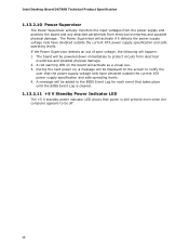
If the Power Supervisor detects an out of spec voltage, the following will be added to the BIOS Event Log for each event that takes place until the BIOS Event Log is still present even when the computer appears to protect circuits from electrical overstress and ...supply voltage rails have deviated outside the current ATX power supply specification and safe operating levels. 4. A message will happen: 1. Intel Desktop Board DX79SR Technical Product Specification 1.13.2.10 Power Supervisor The Power Supervisor actively monitors the input voltages from the power supply and protects the...
If the Power Supervisor detects an out of spec voltage, the following will be added to the BIOS Event Log for each event that takes place until the BIOS Event Log is still present even when the computer appears to protect circuits from electrical overstress and ...supply voltage rails have deviated outside the current ATX power supply specification and safe operating levels. 4. A message will happen: 1. Intel Desktop Board DX79SR Technical Product Specification 1.13.2.10 Power Supervisor The Power Supervisor actively monitors the input voltages from the power supply and protects the...
Product Specification
Page 39
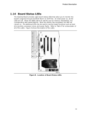
...-on Self-Test. At initial power on . Location of the LEDs. Figure 8 shows the location of Board Status LEDs 39 Figure 8. When the BIOS starts an activity such as hard drive activity, processor errors, and power faults. Product Description 1.14 Board Status LEDs The Desktop Board provides eight board ...
...-on Self-Test. At initial power on . Location of the LEDs. Figure 8 shows the location of Board Status LEDs 39 Figure 8. When the BIOS starts an activity such as hard drive activity, processor errors, and power faults. Product Description 1.14 Board Status LEDs The Desktop Board provides eight board ...
Product Specification
Page 40
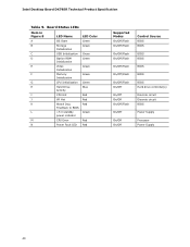
Intel Desktop Board DX79SR Technical Product Specification Table 9. Board Status LEDs Item in Figure 8 LED Name LED Color A OS Start Green B Storage Green Initialization C USB Initialization Green D Option ROM ... E Video Green Initialization F Memory Green Initialization G CPU Initialization Green H Hard Drive Blue Activity I CPU Hot Red J VR Hot Red K Watch Dog Red Fire/Back to BIOS L +5 V standby Green power indicator M CPU Error Red N Power Fault LED Red Supported Modes On/Off/Flash On/Off/Flash On/Off/Flash On/Off/Flash...
Intel Desktop Board DX79SR Technical Product Specification Table 9. Board Status LEDs Item in Figure 8 LED Name LED Color A OS Start Green B Storage Green Initialization C USB Initialization Green D Option ROM ... E Video Green Initialization F Memory Green Initialization G CPU Initialization Green H Hard Drive Blue Activity I CPU Hot Red J VR Hot Red K Watch Dog Red Fire/Back to BIOS L +5 V standby Green power indicator M CPU Error Red N Power Fault LED Red Supported Modes On/Off/Flash On/Off/Flash On/Off/Flash On/Off/Flash...
Product Specification
Page 43
... memory due to an equivalent sized logical address range located just above the top of DRAM (total system memory). These functions include the following: • BIOS/SPI Flash device (64 Mbit) • Local APIC (19 MB) • Direct Media Interface (40 MB) • PCI Express configuration space (256 ...that has 64 GB of system memory installed, it is allocated for Conventional PCI and PCI Express add-in cards, PCI Express configuration space, BIOS (SPI Flash device), and chipset overhead resides above the 4 GB boundary. On a system that is not possible to reclaim the physical memory...
... memory due to an equivalent sized logical address range located just above the top of DRAM (total system memory). These functions include the following: • BIOS/SPI Flash device (64 Mbit) • Local APIC (19 MB) • Direct Media Interface (40 MB) • PCI Express configuration space (256 ...that has 64 GB of system memory installed, it is allocated for Conventional PCI and PCI Express add-in cards, PCI Express configuration space, BIOS (SPI Flash device), and chipset overhead resides above the 4 GB boundary. On a system that is not possible to reclaim the physical memory...
Product Specification
Page 45
Video memory and BIOS Extended BIOS data (movable by the external devices could cause damage to devices inside the computer's chassis, such as IEEE 1394a. Furthermore, improper connection of USB or ... - 9FFFF 80000 - 9FBFF 00000 - 7FFFF Size 65528 MB 64 KB 64 KB 96 KB 160 KB 1 KB 127 KB 512 KB Description Extended memory Runtime BIOS Reserved Potential available high DOS memory (open to the board. Do not use these groups: • Back panel I/O connectors • Component-side I/O connectors and headers...
Video memory and BIOS Extended BIOS data (movable by the external devices could cause damage to devices inside the computer's chassis, such as IEEE 1394a. Furthermore, improper connection of USB or ... - 9FFFF 80000 - 9FBFF 00000 - 7FFFF Size 65528 MB 64 KB 64 KB 96 KB 160 KB 1 KB 127 KB 512 KB Description Extended memory Runtime BIOS Reserved Potential available high DOS memory (open to the board. Do not use these groups: • Back panel I/O connectors • Component-side I/O connectors and headers...


