Product Guide
Page 3
...for installation in homes, offices, schools, computer rooms, and similar locations. It is intended for Intel® Desktop Board DX38BT. Use Only for Intended Applications All Intel Desktop Boards are evaluated as Information Technology Equipment (I.T.E.) for use in this Product Guide are used in personal... about how to prevent damage to hardware or loss of product features 2 Installing and Replacing Desktop Board Components: instructions on how to install the Desktop Board and other hardware components 3 Updating the BIOS: instructions on how to important information. Intended...
...for installation in homes, offices, schools, computer rooms, and similar locations. It is intended for Intel® Desktop Board DX38BT. Use Only for Intended Applications All Intel Desktop Boards are evaluated as Information Technology Equipment (I.T.E.) for use in this Product Guide are used in personal... about how to prevent damage to hardware or loss of product features 2 Installing and Replacing Desktop Board Components: instructions on how to install the Desktop Board and other hardware components 3 Updating the BIOS: instructions on how to important information. Intended...
Product Guide
Page 5
...19 PCI and PCI Express* Auto Configuration 19 Security Passwords 19 Hardware Management 20 Hardware Monitoring and Fan Speed Control 20 Intel® Precision Cooling Technology 20 Chassis Intrusion 20 Power Management 21 Software Support 21 ACPI 21 Hardware Support 21 Power Connectors...24 Onboard Power Button 25 Onboard VR and CPU LEDs 26 Speaker...26 Battery ...27 Real-Time Clock 27 2 Installing and Replacing Desktop Board Components Before You Begin 29 Installation Precautions 30 Prevent Power Supply Overload 30 Observe Safety and Regulatory Requirements 30 Installing the I/O ...
...19 PCI and PCI Express* Auto Configuration 19 Security Passwords 19 Hardware Management 20 Hardware Monitoring and Fan Speed Control 20 Intel® Precision Cooling Technology 20 Chassis Intrusion 20 Power Management 21 Software Support 21 ACPI 21 Hardware Support 21 Power Connectors...24 Onboard Power Button 25 Onboard VR and CPU LEDs 26 Speaker...26 Battery ...27 Real-Time Clock 27 2 Installing and Replacing Desktop Board Components Before You Begin 29 Installation Precautions 30 Prevent Power Supply Overload 30 Observe Safety and Regulatory Requirements 30 Installing the I/O ...
Product Guide
Page 6
Intel Desktop Board DX38BT Product Guide Installing and Removing a Processor 33 Installing a Processor 33 Installing the Processor Fan Heat Sink 37 Connecting the Processor Fan Heat Sink Cable 37 ... 56 Connecting Chassis Fan Cables 56 Connecting Power Supply Cables 57 Setting the BIOS Configuration Jumper 58 Clearing Passwords 59 Replacing the Battery 60 3 Updating the BIOS Updating the BIOS with the Intel® Express BIOS Update Utility 65 Updating the BIOS with the ISO Image BIOS Update File or the Iflash...
Intel Desktop Board DX38BT Product Guide Installing and Removing a Processor 33 Installing a Processor 33 Installing the Processor Fan Heat Sink 37 Connecting the Processor Fan Heat Sink Cable 37 ... 56 Connecting Chassis Fan Cables 56 Connecting Power Supply Cables 57 Setting the BIOS Configuration Jumper 58 Clearing Passwords 59 Replacing the Battery 60 3 Updating the BIOS Updating the BIOS with the Intel® Express BIOS Update Utility 65 Updating the BIOS with the ISO Image BIOS Update File or the Iflash...
Product Guide
Page 27
The battery on the Desktop Board keeps the clock current when the computer is turned off . 27 Desktop Board Features Battery A battery on the Desktop Board keeps the values in CMOS RAM and the clock current when the computer is turned off . Real-Time Clock The Desktop Board has a time-of-day clock and 100-year calendar. Go to page 60 for instructions on how to replace the battery.
The battery on the Desktop Board keeps the clock current when the computer is turned off . 27 Desktop Board Features Battery A battery on the Desktop Board keeps the values in CMOS RAM and the clock current when the computer is turned off . Real-Time Clock The Desktop Board has a time-of-day clock and 100-year calendar. Go to page 60 for instructions on how to replace the battery.

Product Guide
Page 29
... performing any procedures can result in personal injury or equipment damage. 2 Installing and Replacing Desktop Board Components This chapter tells you how to: • Install the I/O shield • Install and remove the Desktop Board • Install and remove a processor • Install the ICH heat sink decorative...• Connect chassis fan and power supply cables • Set the BIOS configuration jumper • Clear passwords • Replace the battery Before You Begin CAUTIONS The procedures in this chapter only at an ESD workstation using and modifying electronic equipment. ...
... performing any procedures can result in personal injury or equipment damage. 2 Installing and Replacing Desktop Board Components This chapter tells you how to: • Install the I/O shield • Install and remove the Desktop Board • Install and remove a processor • Install the ICH heat sink decorative...• Connect chassis fan and power supply cables • Set the BIOS configuration jumper • Clear passwords • Replace the battery Before You Begin CAUTIONS The procedures in this chapter only at an ESD workstation using and modifying electronic equipment. ...
Product Guide
Page 31
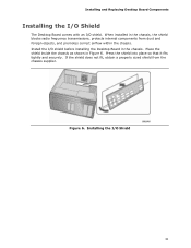
... inside the chassis as shown in the chassis, the shield blocks radio frequency transmissions, protects internal components from the chassis supplier. Installing and Replacing Desktop Board Components Installing the I/O Shield The Desktop Board comes with an I/O shield. If the shield does not fit, obtain a properly sized shield from dust and foreign objects, and promotes correct...
... inside the chassis as shown in the chassis, the shield blocks radio frequency transmissions, protects internal components from the chassis supplier. Installing and Replacing Desktop Board Components Installing the I/O Shield The Desktop Board comes with an I/O shield. If the shield does not fit, obtain a properly sized shield from dust and foreign objects, and promotes correct...

Product Guide
Page 33
Failure to install the processor on the Desktop Board are given below. Open the socket lever by unplugging the power cord from the socket (Figure 8, A and B). the standby power LED should not be lit (... the lever down and away from the computer; Lift the Socket Lever 33 Observe the precautions in "Before You Begin" on page 23). Installing and Replacing Desktop Board Components Installing and Removing a Processor Instructions on how to do so could damage the processor and the...
Failure to install the processor on the Desktop Board are given below. Open the socket lever by unplugging the power cord from the socket (Figure 8, A and B). the standby power LED should not be lit (... the lever down and away from the computer; Lift the Socket Lever 33 Observe the precautions in "Before You Begin" on page 23). Installing and Replacing Desktop Board Components Installing and Removing a Processor Instructions on how to do so could damage the processor and the...

Product Guide
Page 34
Lift the load plate (Figure 9, A). Lift the Load Plate 4. Always replace the socket cover if the processor is removed from the load plate (Figure 10). Figure 10. Remove the Protective Socket Cover 34 Do not discard the protective socket cover. Figure 9. Remove the plastic protective socket cover from the socket. Intel Desktop Board DX38BT Product Guide 3. Do not touch the socket contacts (Figure 9, B).
Lift the load plate (Figure 9, A). Lift the Load Plate 4. Always replace the socket cover if the processor is removed from the load plate (Figure 10). Figure 10. Remove the Protective Socket Cover 34 Do not discard the protective socket cover. Figure 9. Remove the plastic protective socket cover from the socket. Intel Desktop Board DX38BT Product Guide 3. Do not touch the socket contacts (Figure 9, B).

Product Guide
Page 35
Always replace the processor cover if the processor is removed from the Protective Processor Cover 6. Lower the processor straight down without tilting or sliding it in Figure ... processor from the protective processor cover. Do not discard the protective processor cover. Figure 11. Hold the processor with the socket (Figure 12, C). Installing and Replacing Desktop Board Components 5. Figure 12. Install the Processor 35
Always replace the processor cover if the processor is removed from the Protective Processor Cover 6. Lower the processor straight down without tilting or sliding it in Figure ... processor from the protective processor cover. Do not discard the protective processor cover. Figure 11. Hold the processor with the socket (Figure 12, C). Installing and Replacing Desktop Board Components 5. Figure 12. Install the Processor 35

Product Guide
Page 37
Installing and Replacing Desktop Board Components Installing the Processor Fan Heat Sink Desktop Board DX38BT has mounting holes for a processor fan heat sink. For instructions on how to attach the processor fan heat sink to the Desktop Board, refer to the Processor Fan Header 37 Figure 14. However, since the fan with a 3-pin connector (Figure 14, B) can be used...
Installing and Replacing Desktop Board Components Installing the Processor Fan Heat Sink Desktop Board DX38BT has mounting holes for a processor fan heat sink. For instructions on how to attach the processor fan heat sink to the Desktop Board, refer to the Processor Fan Header 37 Figure 14. However, since the fan with a 3-pin connector (Figure 14, B) can be used...

Product Guide
Page 39
... in "Before You Begin" on page 29. 2. Installing and Replacing Desktop Board Components Installing an MCH Heat Sink Fan (Optional) If your system application requires more MCH cooling than that provided by using the fasteners (Figure 16, A) supplied with Desktop Board DX38BT and must be purchased separately. NOTE An MCH heat sink fan ...down until the backet "clicks" into place. 3. You can add a fan to the heat sink by the MCH passive heat sink, you can use the board's 3-pin MCH fan header to supply power to accomodate a 40 mm x 10 mm or 40 mm x 20 mm, 12 V dc fan. To install...
... in "Before You Begin" on page 29. 2. Installing and Replacing Desktop Board Components Installing an MCH Heat Sink Fan (Optional) If your system application requires more MCH cooling than that provided by using the fasteners (Figure 16, A) supplied with Desktop Board DX38BT and must be purchased separately. NOTE An MCH heat sink fan ...down until the backet "clicks" into place. 3. You can add a fan to the heat sink by the MCH passive heat sink, you can use the board's 3-pin MCH fan header to supply power to accomodate a 40 mm x 10 mm or 40 mm x 20 mm, 12 V dc fan. To install...

Product Guide
Page 41
Dual Channel Memory Configuration with Three DIMMs NOTE All other memory configurations will result in DIMM 0 (blue) and DIMM 1 (black) of channel B (see Figure 19). Figure 19. Installing and Replacing Desktop Board Components Figure 18. Dual Channel Memory Configuration with Four DIMMs Three DIMMs If you want to use three DIMMs in a dual-channel configuration, install a matched pair of DIMMs equal in speed and size in single channel memory operation. 41 Install a DIMM equal in speed and total size of the DIMMs installed in channel A in either DIMM 0 or DIMM 1 of channel A.
Dual Channel Memory Configuration with Three DIMMs NOTE All other memory configurations will result in DIMM 0 (blue) and DIMM 1 (black) of channel B (see Figure 19). Figure 19. Installing and Replacing Desktop Board Components Figure 18. Dual Channel Memory Configuration with Four DIMMs Three DIMMs If you want to use three DIMMs in a dual-channel configuration, install a matched pair of DIMMs equal in speed and size in single channel memory operation. 41 Install a DIMM equal in speed and total size of the DIMMs installed in channel A in either DIMM 0 or DIMM 1 of channel A.

Product Guide
Page 43
Installing and Replacing Desktop Board Components To install a DIMM, follow these steps: 1. Observe the precautions in place. 9. Figure 21. Insert the bottom edge of the DIMM until the retaining clips ... it from its anti-static package. 6. Align the small notch at either end of the DIMM with the keys in the socket (see Figure 21). Replace the computer's cover and reconnect the AC power cord. 43 Installing a DIMM 4. Make sure the clips are pushed outward to the computer. Make sure the...
Installing and Replacing Desktop Board Components To install a DIMM, follow these steps: 1. Observe the precautions in place. 9. Figure 21. Insert the bottom edge of the DIMM until the retaining clips ... it from its anti-static package. 6. Align the small notch at either end of the DIMM with the keys in the socket (see Figure 21). Replace the computer's cover and reconnect the AC power cord. 43 Installing a DIMM 4. Make sure the clips are pushed outward to the computer. Make sure the...

Product Guide
Page 44
Gently spread the retaining clips at each end of the socket. 6. Replace the computer's cover and reconnect the AC power cord. 44 The DIMM pops out of the DIMM socket. Turn off the computer. 3. Observe the precautions ... from the socket, and store it away from the computer. 4. Hold the DIMM by the edges, lift it in "Before You Begin" on page 29. 2. Intel Desktop Board DX38BT Product Guide Removing DIMMs To remove a DIMM, follow these steps: 1. Remove the computer's cover. 5. Reinstall and reconnect any parts you removed or disconnected to the...
Gently spread the retaining clips at each end of the socket. 6. Replace the computer's cover and reconnect the AC power cord. 44 The DIMM pops out of the DIMM socket. Turn off the computer. 3. Observe the precautions ... from the socket, and store it away from the computer. 4. Hold the DIMM by the edges, lift it in "Before You Begin" on page 29. 2. Intel Desktop Board DX38BT Product Guide Removing DIMMs To remove a DIMM, follow these steps: 1. Remove the computer's cover. 5. Reinstall and reconnect any parts you removed or disconnected to the...

Product Guide
Page 45
...Express x16 Graphics Cards If you power on the system. Depending on the over-current protection of the power supply, certain Desktop Board components and/or traces may result across the connector pins. If the card is fully seated in the PCI Express connector ...connectors (Figure 22, B). Figure 22. Installing PCI Express x16 Graphics Cards 45 Installing and Replacing Desktop Board Components Installing and Removing a PCI Express x16 Card CAUTION When installing a PCI Express card on the Desktop Board, ensure that the card is not fully seated in the connector, an electrical short may...
...Express x16 Graphics Cards If you power on the system. Depending on the over-current protection of the power supply, certain Desktop Board components and/or traces may result across the connector pins. If the card is fully seated in the PCI Express connector ...connectors (Figure 22, B). Figure 22. Installing PCI Express x16 Graphics Cards 45 Installing and Replacing Desktop Board Components Installing and Removing a PCI Express x16 Card CAUTION When installing a PCI Express card on the Desktop Board, ensure that the card is not fully seated in the connector, an electrical short may...

Product Guide
Page 47
Pull the card straight up. Remove the screw (Figure 24, A) that secures the card's metal bracket to remove a PCI Express x16 card from the connector (C). 4. Figure 24. Push the card ejector lever down using the tip of a pencil or similar tool (Figure 24, B) in "Before You Begin" on page 29. 2. Installing and Replacing Desktop Board Components Removing a PCI Express x16 Card Follow these instructions to the chassis back panel. 3. This will release the card from a connector: 1. Observe the precautions in the notch. Removing a PCI Express x16 Card 47
Pull the card straight up. Remove the screw (Figure 24, A) that secures the card's metal bracket to remove a PCI Express x16 card from the connector (C). 4. Figure 24. Push the card ejector lever down using the tip of a pencil or similar tool (Figure 24, B) in "Before You Begin" on page 29. 2. Installing and Replacing Desktop Board Components Removing a PCI Express x16 Card Follow these instructions to the chassis back panel. 3. This will release the card from a connector: 1. Observe the precautions in the notch. Removing a PCI Express x16 Card 47
Product Guide
Page 49
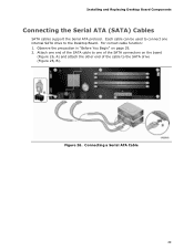
Installing and Replacing Desktop Board Components Connecting the Serial ATA (SATA) Cables SATA cables support the Serial ATA protocol. Figure 26. Each cable can be used to connect one of the SATA connectors on page 29. 2. Attach one end of the SATA cable to one internal SATA drive to the SATA drive (Figure 26, B). Connecting a Serial ATA Cable 49 Observe the precaution in "Before You Begin" on the board (Figure 26, A) and attach the other end of the cable to the Desktop Board. For correct cable function: 1.
Installing and Replacing Desktop Board Components Connecting the Serial ATA (SATA) Cables SATA cables support the Serial ATA protocol. Figure 26. Each cable can be used to connect one of the SATA connectors on page 29. 2. Attach one end of the SATA cable to one internal SATA drive to the SATA drive (Figure 26, B). Connecting a Serial ATA Cable 49 Observe the precaution in "Before You Begin" on the board (Figure 26, A) and attach the other end of the cable to the Desktop Board. For correct cable function: 1.

Product Guide
Page 51
... 6 Ground 8 3.3 Vcc 10 +12 V 12 Key 14 3.3 V STBY 16 Ground Consumer IR (CIR) Headers The Desktop Board has two CIR headers: the input or receiver header (Figure 27, D) and the output or emitter header (Figure 27, C). Installing and Replacing Desktop Board Components Front Panel Audio Header Figure 27, A shows the location of other user remotes.
... 6 Ground 8 3.3 Vcc 10 +12 V 12 Key 14 3.3 V STBY 16 Ground Consumer IR (CIR) Headers The Desktop Board has two CIR headers: the input or receiver header (Figure 27, D) and the output or emitter header (Figure 27, C). Installing and Replacing Desktop Board Components Front Panel Audio Header Figure 27, A shows the location of other user remotes.

Product Guide
Page 53
... no pin) Pin Signal Name 2 TPA1- 4 Ground 6 TPA2- 8 +12 V 10 Ground USB 2.0 Headers Figure 27, G shows the location of the IEEE 1394a header. Installing and Replacing Desktop Board Components IEEE 1394a Header Figure 27, F shows the location of the USB 2.0 headers. IEEE 1394a Header Signal Names Pin Signal Name 1 TPA1+ 3 Ground 5 TPA2+ 7 +12...
... no pin) Pin Signal Name 2 TPA1- 4 Ground 6 TPA2- 8 +12 V 10 Ground USB 2.0 Headers Figure 27, G shows the location of the IEEE 1394a header. Installing and Replacing Desktop Board Components IEEE 1394a Header Figure 27, F shows the location of the USB 2.0 headers. IEEE 1394a Header Signal Names Pin Signal Name 1 TPA1+ 3 Ground 5 TPA2+ 7 +12...

Product Guide
Page 55
...Audio Connectors NOTE The back panel line out connector is designed to the Flexible Audio System After installing the IDT* audio driver from the Intel® Express Installer DVD-ROM, the multi-channel audio feature can be enabled. Item Description A Surround Left and Right B Center Channel...Optical) Figure 28. Poor audio quality may occur if passive (non-amplified) speakers are shown in the table. Installing and Replacing Desktop Board Components Connecting to power either headphones or amplified speakers only. The default connector assignments are connected to this output. 55
...Audio Connectors NOTE The back panel line out connector is designed to the Flexible Audio System After installing the IDT* audio driver from the Intel® Express Installer DVD-ROM, the multi-channel audio feature can be enabled. Item Description A Surround Left and Right B Center Channel...Optical) Figure 28. Poor audio quality may occur if passive (non-amplified) speakers are shown in the table. Installing and Replacing Desktop Board Components Connecting to power either headphones or amplified speakers only. The default connector assignments are connected to this output. 55


