Product Guide
Page 5
Contents 1 Desktop Board Features Supported Operating Systems 11 Desktop Board Components 12 Processor ...14 Main Memory...15 Intel® X38 Express Chipset 15 Audio Subsystem...Configuration 19 Security Passwords 19 Hardware Management 20 Hardware Monitoring and Fan Speed Control 20 Intel® Precision Cooling Technology 20 Chassis Intrusion 20 Power Management 21 Software Support 21 ACPI...26 Battery ...27 Real-Time Clock 27 2 Installing and Replacing Desktop Board Components Before You Begin 29 Installation Precautions 30 Prevent Power Supply Overload 30 Observe Safety ...
Contents 1 Desktop Board Features Supported Operating Systems 11 Desktop Board Components 12 Processor ...14 Main Memory...15 Intel® X38 Express Chipset 15 Audio Subsystem...Configuration 19 Security Passwords 19 Hardware Management 20 Hardware Monitoring and Fan Speed Control 20 Intel® Precision Cooling Technology 20 Chassis Intrusion 20 Power Management 21 Software Support 21 ACPI...26 Battery ...27 Real-Time Clock 27 2 Installing and Replacing Desktop Board Components Before You Begin 29 Installation Precautions 30 Prevent Power Supply Overload 30 Observe Safety ...
Product Guide
Page 7
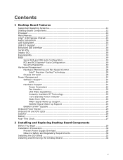
... 2. Location of the Standby Power Indicator 23 4. Installing the I/O Shield 31 7. Desktop Board DX38BT Mounting Screw Hole Locations 32 8. Remove the Processor from the Protective Processor Cover 35 12. Close the Load Plate 36 14. ...Installation of Hazardous Substances (RoHS 79 EU RoHS 79 China RoHS 80 EMC Regulations 82 Ensure Electromagnetic Compatibility (EMC) Compliance 83 Product Certifications 84 Board-Level Certification Markings 84 Chassis and Component Certifications 85 Figures 1. Installing a DIMM 43 22. Installing PCI Express x16 Graphics Cards 45 23. Lift...
... 2. Location of the Standby Power Indicator 23 4. Installing the I/O Shield 31 7. Desktop Board DX38BT Mounting Screw Hole Locations 32 8. Remove the Processor from the Protective Processor Cover 35 12. Close the Load Plate 36 14. ...Installation of Hazardous Substances (RoHS 79 EU RoHS 79 China RoHS 80 EMC Regulations 82 Ensure Electromagnetic Compatibility (EMC) Compliance 83 Product Certifications 84 Board-Level Certification Markings 84 Chassis and Component Certifications 85 Figures 1. Installing a DIMM 43 22. Installing PCI Express x16 Graphics Cards 45 23. Lift...

Product Guide
Page 29
...in personal injury or equipment damage. If such a station is off. 2 Installing and Replacing Desktop Board Components This chapter tells you how to: • Install the I/O shield • Install and remove the Desktop Board • Install and remove a processor • Install the ICH heat sink decorative cover &#...Begin CAUTIONS The procedures in this chapter only at an ESD workstation using and modifying electronic equipment. Some circuitry on the board can continue to operate even though the front panel power button is not available, you can damage components. Perform the ...
...in personal injury or equipment damage. If such a station is off. 2 Installing and Replacing Desktop Board Components This chapter tells you how to: • Install the I/O shield • Install and remove the Desktop Board • Install and remove a processor • Install the ICH heat sink decorative cover &#...Begin CAUTIONS The procedures in this chapter only at an ESD workstation using and modifying electronic equipment. Some circuitry on the board can continue to operate even though the front panel power button is not available, you can damage components. Perform the ...
Product Guide
Page 31
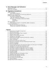
... tightly and securely. Installing and Replacing Desktop Board Components Installing the I/O Shield The Desktop Board comes with an I /O Shield 31 When installed in the chassis, the shield blocks radio frequency transmissions, protects internal components from the chassis supplier. Place the shield inside the chassis as shown in the chassis. Figure 6. If the shield does not fit, obtain a properly sized...
... tightly and securely. Installing and Replacing Desktop Board Components Installing the I/O Shield The Desktop Board comes with an I /O Shield 31 When installed in the chassis, the shield blocks radio frequency transmissions, protects internal components from the chassis supplier. Place the shield inside the chassis as shown in the chassis. Figure 6. If the shield does not fit, obtain a properly sized...

Product Guide
Page 53
... 2 TPA1- 4 Ground 6 TPA2- 8 +12 V 10 Ground USB 2.0 Headers Figure 27, G shows the location of the IEEE 1394a header. Use a shielded cable that have an unshielded cable attached to connect two USB devices. Table 9. Each USB header can be assigned as needed. IEEE 1394a Header Signal... for each USB 2.0 header. Table 10 shows the pin assignments and signal names for a full-speed USB device. 53 Installing and Replacing Desktop Board Components IEEE 1394a Header Figure 27, F shows the location of the USB 2.0 headers. Table 9 shows the pin assignments and signal names ...
... 2 TPA1- 4 Ground 6 TPA2- 8 +12 V 10 Ground USB 2.0 Headers Figure 27, G shows the location of the IEEE 1394a header. Use a shielded cable that have an unshielded cable attached to connect two USB devices. Table 9. Each USB header can be assigned as needed. IEEE 1394a Header Signal... for each USB 2.0 header. Table 10 shows the pin assignments and signal names for a full-speed USB device. 53 Installing and Replacing Desktop Board Components IEEE 1394a Header Figure 27, F shows the location of the USB 2.0 headers. Table 9 shows the pin assignments and signal names ...
Product Guide
Page 83
... following when reading the installation instructions for the host chassis, power supply, and other modules: • Product certifications or lack of certifications • External I/O cable shielding and filtering • Mounting, grounding, and bonding requirements • Keying connectors when mating the wrong connectors could be required on a representative sample of the newly...
... following when reading the installation instructions for the host chassis, power supply, and other modules: • Product certifications or lack of certifications • External I/O cable shielding and filtering • Mounting, grounding, and bonding requirements • Keying connectors when mating the wrong connectors could be required on a representative sample of the newly...