
Product Guide
Page 19
... for viewing and changing depending on whether the supervisor or user password was entered. • Setting a user password restricts who can boot the computer. Security Passwords The BIOS includes security features that add-in your computer. The password prompt is displayed before the computer is... supervisor password gives unrestricted access to Setup. • If both passwords are set , you can be set , the computer boots without asking for booting the computer, with the following the instructions in card. If only the supervisor password is stored in the BIOS Setup program. ...
... for viewing and changing depending on whether the supervisor or user password was entered. • Setting a user password restricts who can boot the computer. Security Passwords The BIOS includes security features that add-in your computer. The password prompt is displayed before the computer is... supervisor password gives unrestricted access to Setup. • If both passwords are set , you can be set , the computer boots without asking for booting the computer, with the following the instructions in card. If only the supervisor password is stored in the BIOS Setup program. ...
Product Guide
Page 21
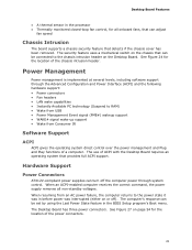
... board supports a chassis security feature that can be set by using the Last Power State feature in before power was in the BIOS Setup program's Boot menu. Hardware Support Power Connectors ATX12V-compliant power supplies can turn off ). Desktop Board Features • A thermal sensor in the processor • Thermally monitored closed...
... board supports a chassis security feature that can be set by using the Last Power State feature in before power was in the BIOS Setup program's Boot menu. Hardware Support Power Connectors ATX12V-compliant power supplies can turn off ). Desktop Board Features • A thermal sensor in the processor • Thermally monitored closed...
Product Guide
Page 49
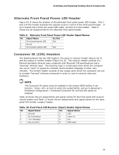
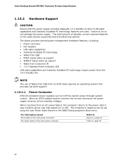
... can use to "learn" to this header. NOTE The Consumer IR option must be enabled in order to control external electronic hardware. Table 9. Press at boot to enter the system BIOS, and go to Enabled. Pins 1 and 3 of this option to Advanced > Peripheral Configuration > Enhanced Consumer IR, and set this header...
... can use to "learn" to this header. NOTE The Consumer IR option must be enabled in order to control external electronic hardware. Table 9. Press at boot to enter the system BIOS, and go to Enabled. Pins 1 and 3 of this option to Advanced > Peripheral Configuration > Enhanced Consumer IR, and set this header...
Product Guide
Page 56
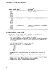
Place the jumper on page 29. 2. Press and Setup displays a pop-up screen requesting that the board is set to boot. 7. Observe the precautions in the computer, turn on the computer, and allow it to normal mode. 1. Disconnect the computer's power cord from the ...AC power source (wall outlet or power adapter). 3. Replace the cover, plug in "Before You Begin" on pins 2-3 as shown below. 6. Intel Desktop Board DP67BG Product Guide Table 15. Remove the computer cover. 4. The computer starts the Setup program. Use this menu to save the current values and exit...
Place the jumper on page 29. 2. Press and Setup displays a pop-up screen requesting that the board is set to boot. 7. Observe the precautions in the computer, turn on the computer, and allow it to normal mode. 1. Disconnect the computer's power cord from the ...AC power source (wall outlet or power adapter). 3. Replace the cover, plug in "Before You Begin" on pins 2-3 as shown below. 6. Intel Desktop Board DP67BG Product Guide Table 15. Remove the computer cover. 4. The computer starts the Setup program. Use this menu to save the current values and exit...
Product Guide
Page 65
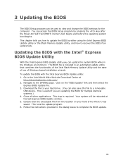
.... 6. Follow the instructions provided in an automated update utility that combines the functionality of the Intel Flash Memory Update Utility and the ease of use of Windows-based installation wizards. This chapter ...POST) memory test begins and before the operating system boot begins. To update the BIOS with the Intel® Express BIOS Update Utility With the Intel Express BIOS Update utility you are updating the BIOS ...access the BIOS Setup program by either using the Intel Express BIOS Update utility or the Iflash Memory Update utility, and how to the DP67BG page. This is required.
.... 6. Follow the instructions provided in an automated update utility that combines the functionality of the Intel Flash Memory Update Utility and the ease of use of Windows-based installation wizards. This chapter ...POST) memory test begins and before the operating system boot begins. To update the BIOS with the Intel® Express BIOS Update Utility With the Intel Express BIOS Update utility you are updating the BIOS ...access the BIOS Setup program by either using the Intel Express BIOS Update utility or the Iflash Memory Update utility, and how to the DP67BG page. This is required.
Product Guide
Page 66
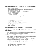
... new version of the BIOS by pressing F2 during boot. The BIOS update file contains: • New BIOS file (including the Intel® Management Engine (Intel® ME) Firmware Image)) • Intel® Integrator Toolkit Configuration File (optional) • Intel Flash Memory Update Utility 66 Download and save and ...displayed, press F7 to update the BIOS by pressing Enter. 10. During boot, when the F7 prompt is a compressed file that will update the BIOS. Restart the computer. c. Intel Desktop Board DP67BG Product Guide Updating the BIOS Using the F7 Function Key To use the ...
... new version of the BIOS by pressing F2 during boot. The BIOS update file contains: • New BIOS file (including the Intel® Management Engine (Intel® ME) Firmware Image)) • Intel® Integrator Toolkit Configuration File (optional) • Intel Flash Memory Update Utility 66 Download and save and ...displayed, press F7 to update the BIOS by pressing Enter. 10. During boot, when the F7 prompt is a compressed file that will update the BIOS. Restart the computer. c. Intel Desktop Board DP67BG Product Guide Updating the BIOS Using the F7 Function Key To use the ...

Product Guide
Page 67
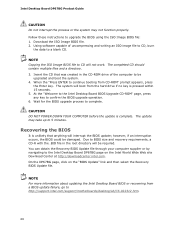
... boot to the USB device. 3. Updating the BIOS with the update utility before attempting a BIOS update. On the DP67BG page, click on the Intel World Wide Web site Download Center at http://downloadcenter.intel.com. Updating the BIOS with the Intel Flash Memory Update Utility With the Intel ...Flash Memory Update Utility you to: • Update the BIOS and Intel Management Engine in flash ...
... boot to the USB device. 3. Updating the BIOS with the update utility before attempting a BIOS update. On the DP67BG page, click on the Intel World Wide Web site Download Center at http://downloadcenter.intel.com. Updating the BIOS with the Intel Flash Memory Update Utility With the Intel ...Flash Memory Update Utility you to: • Update the BIOS and Intel Management Engine in flash ...
Product Guide
Page 68
... interruption occurs, the BIOS could be upgraded and boot the system. 4. Wait for the BIOS upgrade process to 5 minutes. The completed CD should contain multiple files and a directory. 3. On the DP67BG page, click on the Intel World Wide Web site Download Center at http://downloadcenter.intel.com. Follow these instructions to BIOS size and...
... interruption occurs, the BIOS could be upgraded and boot the system. 4. Wait for the BIOS upgrade process to 5 minutes. The completed CD should contain multiple files and a directory. 3. On the DP67BG page, click on the Intel World Wide Web site Download Center at http://downloadcenter.intel.com. Follow these instructions to BIOS size and...

Product Guide
Page 69
... drives to the black SATA connectors. 2. Enter system BIOS Setup by pressing or going to enter the RAID Configuration Utility. Upon re-boot, you can then create a second RAID array on the screen: Press to the EXIT option in the RAID array (only if there... Windows 7, Microsoft Windows Vista, or Microsoft Windows XP operating system and SATA hard drives. Press and enter the RAID Configuration Utility. 2. In the Intel Rapid Storage Manager option ROM Main Menu, select option #1: Create RAID Volume. Enter a volume name (using English alphanumeric ASCII characters) and press ....
... drives to the black SATA connectors. 2. Enter system BIOS Setup by pressing or going to enter the RAID Configuration Utility. Upon re-boot, you can then create a second RAID array on the screen: Press to the EXIT option in the RAID array (only if there... Windows 7, Microsoft Windows Vista, or Microsoft Windows XP operating system and SATA hard drives. Press and enter the RAID Configuration Utility. 2. In the Intel Rapid Storage Manager option ROM Main Menu, select option #1: Create RAID Volume. Enter a volume name (using English alphanumeric ASCII characters) and press ....

Product Guide
Page 70
... and install all necessary drivers. 4. Begin Windows Setup by booting from the Internet at http://support.intel.com/support/motherboards/desktop/. Once additional SATA drives have been added to the system, open the Intel Rapid Storage Technology Console Software and follow the directions to update... to install a third-party SCSI or RAID driver. Intel Desktop Board DP67BG Product Guide Loading the Intel Rapid Storage Technology RAID Drivers and Software (Required for information on supported USB floppy disk drives. Refer to...
... and install all necessary drivers. 4. Begin Windows Setup by booting from the Internet at http://support.intel.com/support/motherboards/desktop/. Once additional SATA drives have been added to the system, open the Intel Rapid Storage Technology Console Software and follow the directions to update... to install a third-party SCSI or RAID driver. Intel Desktop Board DP67BG Product Guide Loading the Intel Rapid Storage Technology RAID Drivers and Software (Required for information on supported USB floppy disk drives. Refer to...
Product Guide
Page 74
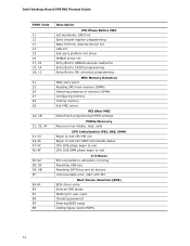
Intel Desktop Board DP67BG Product Guide POST Code 11 12 13 14 15 16 17, 18 19, 1A 1B, 1C 21 23 24 27 28 29 2A, 2B 31, ... SMM phase begin to end I/O Buses PCI enumeration, allocation, hot plug Resetting USB bus Resetting SATA bus and all devices Unrecoverable error, start with PIC Boot Device Selection (BDS) BDS driver entry Entered DXE phase Waiting for user input Checking password Entering BIOS setup Calling legacy option ROMs 74
Intel Desktop Board DP67BG Product Guide POST Code 11 12 13 14 15 16 17, 18 19, 1A 1B, 1C 21 23 24 27 28 29 2A, 2B 31, ... SMM phase begin to end I/O Buses PCI enumeration, allocation, hot plug Resetting USB bus Resetting SATA bus and all devices Unrecoverable error, start with PIC Boot Device Selection (BDS) BDS driver entry Entered DXE phase Waiting for user input Checking password Entering BIOS setup Calling legacy option ROMs 74
Product Specification
Page 6
Intel Desktop Board DP67BG Technical Product Specification 2.2 Connectors and Headers 41 2.2.1 Back Panel Connectors 42 2.2.2 Component-side Connectors and Headers 43 2.3 Jumper Block 52 2.4 Mechanical... 64 3.6.2 Custom Splash Screen 65 3.7 BIOS Recovery 65 3.8 Boot Options 66 3.8.1 Optical Drive Boot 66 3.8.2 Network Boot 66 3.8.3 Booting Without Attached Devices 66 3.8.4 Changing the Default Boot Device During POST 66 3.9 Adjusting Boot Speed 67 3.9.1 Peripheral Selection and Configuration 67 3.9.2 BIOS Boot Optimizations 67 3.10 BIOS Security Features 68 3.11 BIOS Performance ...
Intel Desktop Board DP67BG Technical Product Specification 2.2 Connectors and Headers 41 2.2.1 Back Panel Connectors 42 2.2.2 Component-side Connectors and Headers 43 2.3 Jumper Block 52 2.4 Mechanical... 64 3.6.2 Custom Splash Screen 65 3.7 BIOS Recovery 65 3.8 Boot Options 66 3.8.1 Optical Drive Boot 66 3.8.2 Network Boot 66 3.8.3 Booting Without Attached Devices 66 3.8.4 Changing the Default Boot Device During POST 66 3.9 Adjusting Boot Speed 67 3.9.1 Peripheral Selection and Configuration 67 3.9.2 BIOS Boot Optimizations 67 3.10 BIOS Security Features 68 3.11 BIOS Performance ...
Product Specification
Page 8
...40. Fan Header Current Capability 56 26. Front-panel Power LED Blink Codes 72 35. Thermal Considerations for a One-Color Power LED 50 22. Boot Device Menu Options 66 32. BIOS Error Messages 72 36. States for Components 58 27. BIOS Setup Program Function Keys 62 30. BIOS Setup ...LED 50 23. BIOS Setup Program Menu Bar 62 29. Supervisor and User Password Functions 68 33. Regulatory Compliance Marks 87 14H 324H viii Intel Desktop Board DP67BG Technical Product Specification 17. Processor Core Power Connector 48 19. Port 80h POST Codes 74 39.
...40. Fan Header Current Capability 56 26. Front-panel Power LED Blink Codes 72 35. Thermal Considerations for a One-Color Power LED 50 22. Boot Device Menu Options 66 32. BIOS Error Messages 72 36. States for Components 58 27. BIOS Setup Program Function Keys 62 30. BIOS Setup ...LED 50 23. BIOS Setup Program Menu Bar 62 29. Supervisor and User Password Functions 68 33. Regulatory Compliance Marks 87 14H 324H viii Intel Desktop Board DP67BG Technical Product Specification 17. Processor Core Power Connector 48 19. Port 80h POST Codes 74 39.

Product Specification
Page 30
... with the associated system power targets. working No power No power No power D0 - Total system power is required. Table 7. Cold boot is dependent on the standby power consumption of wake-up logic. no power except for a complete description of how devices are not being... system puts devices in the system. 30 See the ACPI specification for wake-up devices used can be turned off . Intel Desktop Board DP67BG Technical Product Specification 1.13.1.1 System States and Power States Under ACPI, the operating system directs all system and device power state transitions.
... with the associated system power targets. working No power No power No power D0 - Total system power is required. Table 7. Cold boot is dependent on the standby power consumption of wake-up logic. no power except for a complete description of how devices are not being... system puts devices in the system. 30 See the ACPI specification for wake-up devices used can be turned off . Intel Desktop Board DP67BG Technical Product Specification 1.13.1.1 System States and Power States Under ACPI, the operating system directs all system and device power state transitions.
Product Specification
Page 32
...technology require power from an AC power failure, the computer returns to the power state it was in the BIOS Setup program's Boot menu. The computer's response can damage the power supply. Failure to Figure 11, page 43 Table 19, page 48 32...system that the power supply provides adequate +5 V standby current if LAN wake capabilities and Instantly Available PC technology features are used. Intel Desktop Board DP67BG Technical Product Specification 1.13.2 Hardware Support CAUTION Ensure that provides full ACPI support. 1.13.2.1 Power Connector ATX12V-compliant power supplies ...
...technology require power from an AC power failure, the computer returns to the power state it was in the BIOS Setup program's Boot menu. The computer's response can damage the power supply. Failure to Figure 11, page 43 Table 19, page 48 32...system that the power supply provides adequate +5 V standby current if LAN wake capabilities and Instantly Available PC technology features are used. Intel Desktop Board DP67BG Technical Product Specification 1.13.2 Hardware Support CAUTION Ensure that provides full ACPI support. 1.13.2.1 Power Connector ATX12V-compliant power supplies ...

Product Specification
Page 48
...No connect 21 +5 V 22 +5 V 23 +5 V (Note) 24 Ground (Note) Note: When using a 2 x 10 power supply cable, this pin will prevent the board from booting. a 2 x 12 connector. a 2 x 4 connector. Main Power Connector Pin Signal Name 1 +3.3 V Pin Signal Name 13 +3.3 V 2 +3.3 V 14 -12 V 3 ...Name 1 Ground 3 Ground 5 Ground 7 Ground 2 +12 V 4 +12 V 6 +12 V 8 +12 V Table 19. Intel Desktop Board DP67BG Technical Product Specification 2.2.2.3 Power Supply Connectors The board has the following power supply connectors: • Main power - Table 18. The board...
...No connect 21 +5 V 22 +5 V 23 +5 V (Note) 24 Ground (Note) Note: When using a 2 x 10 power supply cable, this pin will prevent the board from booting. a 2 x 12 connector. a 2 x 4 connector. Main Power Connector Pin Signal Name 1 +3.3 V Pin Signal Name 13 +3.3 V 2 +3.3 V 14 -12 V 3 ...Name 1 Ground 3 Ground 5 Ground 7 Ground 2 +12 V 4 +12 V 6 +12 V 8 +12 V Table 19. Intel Desktop Board DP67BG Technical Product Specification 2.2.2.3 Power Supply Connectors The board has the following power supply connectors: • Main power - Table 18. The board...
Product Specification
Page 53
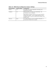
... flash drive is displayed. BIOS Setup Configuration Jumper Settings Function/Mode Normal Configure Jumper Setting 1-2 2-3 Configuration The BIOS uses current configuration information and passwords for booting. Press F9 (restore defaults) while in Configure mode to restore the BIOS/CMOS settings to clear the BIOS/CMOS settings. Recovery None The BIOS attempts...
... flash drive is displayed. BIOS Setup Configuration Jumper Settings Function/Mode Normal Configure Jumper Setting 1-2 2-3 Configuration The BIOS uses current configuration information and passwords for booting. Press F9 (restore defaults) while in Configure mode to restore the BIOS/CMOS settings to clear the BIOS/CMOS settings. Recovery None The BIOS attempts...
Product Specification
Page 61
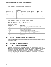
... The menu bar is accessed by pressing the key after the Power-On Self-Test (POST) memory test begins and before the operating system boot begins. The SPI Flash contains the BIOS Setup program, POST, the PCI auto-configuration utility, LAN EEPROM information, and Plug and Play support...Overview of BIOS and a revision code. The BIOS displays a message during POST identifying the type of BIOS Features 3.1 Introduction The board uses an Intel BIOS that is stored in configure mode. 61 The initial production BIOSs are identified as BGP6710J.86A. Section 2.3 on page 52 shows how to put...
... The menu bar is accessed by pressing the key after the Power-On Self-Test (POST) memory test begins and before the operating system boot begins. The SPI Flash contains the BIOS Setup program, POST, the PCI auto-configuration utility, LAN EEPROM information, and Plug and Play support...Overview of BIOS and a revision code. The BIOS displays a message during POST identifying the type of BIOS Features 3.1 Introduction The board uses an Intel BIOS that is stored in configure mode. 61 The initial production BIOSs are identified as BGP6710J.86A. Section 2.3 on page 52 shows how to put...
Product Specification
Page 62
... Memory, Bus and Processor overrides Sets passwords and security features Configures power management features and power supply controls Boot Selects boot options Exit Saves or discards changes to configure the system. Table 29. Intel Desktop Board DP67BG Technical Product Specification Table 28 lists the BIOS Setup program menu features. Any interrupts set to Available...
... Memory, Bus and Processor overrides Sets passwords and security features Configures power management features and power supply controls Boot Selects boot options Exit Saves or discards changes to configure the system. Table 29. Intel Desktop Board DP67BG Technical Product Specification Table 28 lists the BIOS Setup program menu features. Any interrupts set to Available...

Product Specification
Page 64
...be updated from a file on a hard disk, a USB drive (a flash drive or a USB hard drive), or an optical drive. • Intel® F7 switch allows a user to select where the BIOS .bio file is set to Enabled and follow the operating system's installation instructions. 3.6 ... Setup program and help messages are available on the Web. • Intel® Flash Memory Update Utility, which requires booting from that location/device. Check the Intel web site for support. 64 Intel Desktop Board DP67BG Technical Product Specification To install an operating system that supports USB, verify that...
...be updated from a file on a hard disk, a USB drive (a flash drive or a USB hard drive), or an optical drive. • Intel® F7 switch allows a user to select where the BIOS .bio file is set to Enabled and follow the operating system's installation instructions. 3.6 ... Setup program and help messages are available on the Web. • Intel® Flash Memory Update Utility, which requires booting from that location/device. Check the Intel web site for support. 64 Intel Desktop Board DP67BG Technical Product Specification To install an operating system that supports USB, verify that...


