
Product Guide
Page 19
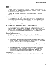
... If you install a Serial ATA device (such as a hard drive) in your computer. The BIOS can be accessed and who can boot the computer. The password prompt is displayed before the computer is set , pressing at the password prompt of Setup gives the user restricted access... after you must enter either password to run the BIOS Setup program after installing a Serial ATA. The BIOS is set , the computer boots without asking for that restrict whether the BIOS Setup program can override the auto-configuration options by following restrictions: • The supervisor password...
... If you install a Serial ATA device (such as a hard drive) in your computer. The BIOS can be accessed and who can boot the computer. The password prompt is displayed before the computer is set , pressing at the password prompt of Setup gives the user restricted access... after you must enter either password to run the BIOS Setup program after installing a Serial ATA. The BIOS is set , the computer boots without asking for that restrict whether the BIOS Setup program can override the auto-configuration options by following restrictions: • The supervisor password...
Product Guide
Page 21
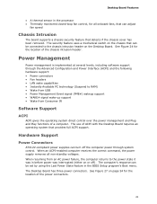
... ACPI with the Desktop Board requires an operating system that can be set by using the Last Power State feature in the BIOS Setup program's Boot menu. See Figure 27 on the Desktop Board. Power Management Power management is implemented at several levels, including software support through system control. The computer...
... ACPI with the Desktop Board requires an operating system that can be set by using the Last Power State feature in the BIOS Setup program's Boot menu. See Figure 27 on the Desktop Board. Power Management Power management is implemented at several levels, including software support through system control. The computer...
Product Guide
Page 49
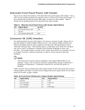
... front panel power LED header. Table 10. The learning input is a high-pass input which the computer can use to "learn" to Enabled. Press at boot to enter the system BIOS, and go to Advanced > Peripheral Configuration > Enhanced Consumer IR, and set this header duplicate the signals on pins 2 and 4 of...
... front panel power LED header. Table 10. The learning input is a high-pass input which the computer can use to "learn" to Enabled. Press at boot to enter the system BIOS, and go to Advanced > Peripheral Configuration > Enhanced Consumer IR, and set this header duplicate the signals on pins 2 and 4 of...
Product Guide
Page 56
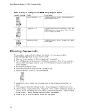
... the password. Turn off all peripheral devices connected to boot. 7. Replace the cover, plug in the computer and the configuration jumper block is set to save the current values and exit Setup. 56 Intel Desktop Board DP67BG Product Guide Table 15. Jumper Settings for the BIOS... Setup Program Modes Jumper Setting Mode Normal (default) (1-2) Description The BIOS uses the current configuration and passwords for booting. Observe the precautions in the event of ...
... the password. Turn off all peripheral devices connected to boot. 7. Replace the cover, plug in the computer and the configuration jumper block is set to save the current values and exit Setup. 56 Intel Desktop Board DP67BG Product Guide Table 15. Jumper Settings for the BIOS... Setup Program Modes Jumper Setting Mode Normal (default) (1-2) Description The BIOS uses the current configuration and passwords for booting. Observe the precautions in the event of ...
Product Guide
Page 65
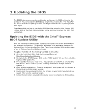
...utility: 1. Follow the instructions provided in the dialog boxes to the DP67BG page. Navigate to complete the BIOS update. 65 Click on your hard drive. (You can access the BIOS Setup program by either using the Intel Express BIOS Update utility or the Iflash Memory Update utility, and ...Test (POST) memory test begins and before the operating system boot begins. This is useful if you can be rebooted at http://downloadcenter.intel.com/ 2. To update the BIOS with the Intel® Express BIOS Update Utility With the Intel Express BIOS Update utility you are updating the BIOS for ...
...utility: 1. Follow the instructions provided in the dialog boxes to the DP67BG page. Navigate to complete the BIOS update. 65 Click on your hard drive. (You can access the BIOS Setup program by either using the Intel Express BIOS Update utility or the Iflash Memory Update utility, and ...Test (POST) memory test begins and before the operating system boot begins. This is useful if you can be rebooted at http://downloadcenter.intel.com/ 2. To update the BIOS with the Intel® Express BIOS Update Utility With the Intel Express BIOS Update utility you are updating the BIOS for ...
Product Guide
Page 66
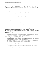
...complete. 11. Download and save and exit. 6. Shut down the target computer. 5. b. During boot, when the F7 prompt is a compressed file that will update the BIOS. Updating the BIOS with the Intel® Flash Memory Update Utility or the ISO Image BIOS Update File You can use this section... Image BIOS update file is a standardized image of a bootable CD-ROM that can update to update the BIOS by pressing F2 during boot. Intel Desktop Board DP67BG Product Guide Updating the BIOS Using the F7 Function Key To use the information in this BIOS update method: 1. Wait 2-5 minutes for...
...complete. 11. Download and save and exit. 6. Shut down the target computer. 5. b. During boot, when the F7 prompt is a compressed file that will update the BIOS. Updating the BIOS with the Intel® Flash Memory Update Utility or the ISO Image BIOS Update File You can use this section... Image BIOS update file is a standardized image of a bootable CD-ROM that can update to update the BIOS by pressing F2 during boot. Intel Desktop Board DP67BG Product Guide Updating the BIOS Using the F7 Function Key To use the information in this BIOS update method: 1. Wait 2-5 minutes for...

Product Guide
Page 67
...can obtain either of these files through your computer supplier or by navigating to the Intel Desktop Board DP67BG page on the Intel World Wide Web site provides a simple method for the update of an Intel® Desktop Board BIOS to the latest production release regardless of uncompressing and writing the...a BIOS update. Updating the BIOS with the Intel Flash Memory Update Utility With the Intel Flash Memory Update Utility you to upgrade the BIOS via the Intel Flash Memory Utility. 67 Configure the BIOS or use the F10 option during POST to boot to a bootable USB flash drive or other ...
...can obtain either of these files through your computer supplier or by navigating to the Intel Desktop Board DP67BG page on the Intel World Wide Web site provides a simple method for the update of an Intel® Desktop Board BIOS to the latest production release regardless of uncompressing and writing the...a BIOS update. Updating the BIOS with the Intel Flash Memory Update Utility With the Intel Flash Memory Update Utility you to upgrade the BIOS via the Intel Flash Memory Utility. 67 Configure the BIOS or use the F10 option during POST to boot to a bootable USB flash drive or other ...
Product Guide
Page 68
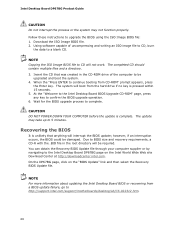
... CD. NOTE Copying the ISO Image BIOS file to CD will be damaged. When the "Press ENTER to continue booting from a BIOS update failure, go to http://support.intel.com/support/motherboards/desktop/sb/CS-022312.htm. 68 CAUTION DO NOT POWER DOWN YOUR COMPUTER before the update is ... multiple files and a directory. 3. The system will interrupt the BIOS update; Insert the CD that anything will boot from the hard drive if no key is complete. Intel Desktop Board DP67BG Product Guide CAUTION Do not interrupt the process or the system may take up to 5 minutes. Download the ISO...
... CD. NOTE Copying the ISO Image BIOS file to CD will be damaged. When the "Press ENTER to continue booting from a BIOS update failure, go to http://support.intel.com/support/motherboards/desktop/sb/CS-022312.htm. 68 CAUTION DO NOT POWER DOWN YOUR COMPUTER before the update is ... multiple files and a directory. 3. The system will interrupt the BIOS update; Insert the CD that anything will boot from the hard drive if no key is complete. Intel Desktop Board DP67BG Product Guide CAUTION Do not interrupt the process or the system may take up to 5 minutes. Download the ISO...

Product Guide
Page 69
...boot, you have selected the RAID LEVEL. 4. Select the drives to be used in the MAIN MENU. 69 Exit the Option ROM user interface by pressing or going to enter the RAID Configuration Utility. Press and enter the RAID Configuration Utility. 2. Press once you will see the following Intel...8. Enter a volume name (using English alphanumeric ASCII characters) and press . 3. 4 Configuring for RAID Using Intel® Rapid Storage Technology NOTE Intel Rapid Storage Technology requires Microsoft Windows 7, Microsoft Windows Vista, or Microsoft Windows XP operating system and SATA hard ...
...boot, you have selected the RAID LEVEL. 4. Select the drives to be used in the MAIN MENU. 69 Exit the Option ROM user interface by pressing or going to enter the RAID Configuration Utility. Press and enter the RAID Configuration Utility. 2. Press once you will see the following Intel...8. Enter a volume name (using English alphanumeric ASCII characters) and press . 3. 4 Configuring for RAID Using Intel® Rapid Storage Technology NOTE Intel Rapid Storage Technology requires Microsoft Windows 7, Microsoft Windows Vista, or Microsoft Windows XP operating system and SATA hard ...

Product Guide
Page 70
... have been added to the system, open the Intel Rapid Storage Technology Console Software and follow the directions to update to install a third-party SCSI or RAID driver. Intel Desktop Board DP67BG Product Guide Loading the Intel Rapid Storage Technology RAID Drivers and Software (Required ...in a USB floppy disk drive. Setting Up a "RAID Ready" System The Intel Rapid Storage Technology Console software offers the flexibility to upgrade from the Windows installation CD. 2. Begin Windows Setup by booting from a single Serial ATA drive to RAID without reinstalling the operating system, when...
... have been added to the system, open the Intel Rapid Storage Technology Console Software and follow the directions to update to install a third-party SCSI or RAID driver. Intel Desktop Board DP67BG Product Guide Loading the Intel Rapid Storage Technology RAID Drivers and Software (Required ...in a USB floppy disk drive. Setting Up a "RAID Ready" System The Intel Rapid Storage Technology Console software offers the flexibility to upgrade from the Windows installation CD. 2. Begin Windows Setup by booting from a single Serial ATA drive to RAID without reinstalling the operating system, when...
Product Guide
Page 74
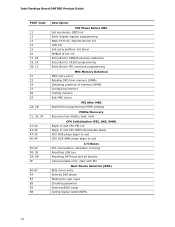
Intel Desktop Board DP67BG Product Guide POST Code 11 12 13 14 15 16 17, 18 19, 1A 1B, 1C 21 23 24 27 28 29 2A, 2B 31, ... SMM phase begin to end I/O Buses PCI enumeration, allocation, hot plug Resetting USB bus Resetting SATA bus and all devices Unrecoverable error, start with PIC Boot Device Selection (BDS) BDS driver entry Entered DXE phase Waiting for user input Checking password Entering BIOS setup Calling legacy option ROMs 74
Intel Desktop Board DP67BG Product Guide POST Code 11 12 13 14 15 16 17, 18 19, 1A 1B, 1C 21 23 24 27 28 29 2A, 2B 31, ... SMM phase begin to end I/O Buses PCI enumeration, allocation, hot plug Resetting USB bus Resetting SATA bus and all devices Unrecoverable error, start with PIC Boot Device Selection (BDS) BDS driver entry Entered DXE phase Waiting for user input Checking password Entering BIOS setup Calling legacy option ROMs 74
Product Specification
Page 6
Intel Desktop Board DP67BG Technical Product Specification 2.2 Connectors and Headers 41 2.2.1 Back Panel Connectors 42 2.2.2 Component-side Connectors and Headers 43 2.3 Jumper Block 52 2.4 Mechanical... 64 3.6.2 Custom Splash Screen 65 3.7 BIOS Recovery 65 3.8 Boot Options 66 3.8.1 Optical Drive Boot 66 3.8.2 Network Boot 66 3.8.3 Booting Without Attached Devices 66 3.8.4 Changing the Default Boot Device During POST 66 3.9 Adjusting Boot Speed 67 3.9.1 Peripheral Selection and Configuration 67 3.9.2 BIOS Boot Optimizations 67 3.10 BIOS Security Features 68 3.11 BIOS Performance ...
Intel Desktop Board DP67BG Technical Product Specification 2.2 Connectors and Headers 41 2.2.1 Back Panel Connectors 42 2.2.2 Component-side Connectors and Headers 43 2.3 Jumper Block 52 2.4 Mechanical... 64 3.6.2 Custom Splash Screen 65 3.7 BIOS Recovery 65 3.8 Boot Options 66 3.8.1 Optical Drive Boot 66 3.8.2 Network Boot 66 3.8.3 Booting Without Attached Devices 66 3.8.4 Changing the Default Boot Device During POST 66 3.9 Adjusting Boot Speed 67 3.9.1 Peripheral Selection and Configuration 67 3.9.2 BIOS Boot Optimizations 67 3.10 BIOS Security Features 68 3.11 BIOS Performance ...
Product Specification
Page 8
.... Recommended Power Supply Current Values 55 25. Fan Header Current Capability 56 26. Supervisor and User Password Functions 68 33. BIOS Beep Codes 71 34. Boot Device Menu Options 66 32. Front-panel Power LED Blink Codes 72 35. BIOS Error Messages 72 36. Environmental Specifications 59 28. BIOS Setup Program... Function Keys 62 30. EMC Regulations 83 32H 41. Regulatory Compliance Marks 87 14H 324H viii BIOS Setup Configuration Jumper Settings 53 24. Intel Desktop Board DP67BG Technical Product Specification 17. Safety Standards 79 40.
.... Recommended Power Supply Current Values 55 25. Fan Header Current Capability 56 26. Supervisor and User Password Functions 68 33. BIOS Beep Codes 71 34. Boot Device Menu Options 66 32. Front-panel Power LED Blink Codes 72 35. BIOS Error Messages 72 36. Environmental Specifications 59 28. BIOS Setup Program... Function Keys 62 30. EMC Regulations 83 32H 41. Regulatory Compliance Marks 87 14H 324H viii BIOS Setup Configuration Jumper Settings 53 24. Intel Desktop Board DP67BG Technical Product Specification 17. Safety Standards 79 40.

Product Specification
Page 30
...System Power Global States Sleeping States Processor States Device States Targeted System Power (Note 1) G0 - working state G1 - S4 - Intel Desktop Board DP67BG Technical Product Specification 1.13.1.1 System States and Power States Under ACPI, the operating system directs all system and device power state .... sleeping state G1 - sleeping state G2/S5 S0 - Suspend to disk. Context saved to RAM. Context not saved. Cold boot is dependent on user preferences and knowledge of wake-up logic. working state. working No power No power No power D0 - ...
...System Power Global States Sleeping States Processor States Device States Targeted System Power (Note 1) G0 - working state G1 - S4 - Intel Desktop Board DP67BG Technical Product Specification 1.13.1.1 System States and Power States Under ACPI, the operating system directs all system and device power state .... sleeping state G1 - sleeping state G2/S5 S0 - Suspend to disk. Context saved to RAM. Context not saved. Cold boot is dependent on user preferences and knowledge of wake-up logic. working state. working No power No power No power D0 - ...
Product Specification
Page 32
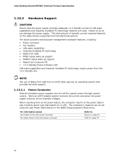
...of Wake from USB from an AC power failure, the computer returns to the power state it was in the BIOS Setup program's Boot menu. Failure to Figure 11, page 43 Table 19, page 48 32 For information about The location of the main power connector The... signal names of standby current required depends on or off the system power through system control. Intel Desktop Board DP67BG Technical Product Specification 1.13.2 Hardware Support CAUTION Ensure that provides full ACPI support. 1.13.2.1 Power Connector ATX12V-compliant power supplies can ...
...of Wake from USB from an AC power failure, the computer returns to the power state it was in the BIOS Setup program's Boot menu. Failure to Figure 11, page 43 Table 19, page 48 32 For information about The location of the main power connector The... signal names of standby current required depends on or off the system power through system control. Intel Desktop Board DP67BG Technical Product Specification 1.13.2 Hardware Support CAUTION Ensure that provides full ACPI support. 1.13.2.1 Power Connector ATX12V-compliant power supplies can ...

Product Specification
Page 48
When using a 2 x 10 power supply cable, this pin will prevent the board from booting. This connector provides power directly to the processor voltage regulator and must always be unconnected. The board supports the use... V Pin Signal Name 13 +3.3 V 2 +3.3 V 14 -12 V 3 Ground 4 +5 V 5 Ground 6 +5 V 15 Ground 16 PS-ON# (power supply remote on page 55 48 Intel Desktop Board DP67BG Technical Product Specification 2.2.2.3 Power Supply Connectors The board has the following power supply connectors: • Main power - This connector is compatible with 2 x 10 connectors...
When using a 2 x 10 power supply cable, this pin will prevent the board from booting. This connector provides power directly to the processor voltage regulator and must always be unconnected. The board supports the use... V Pin Signal Name 13 +3.3 V 2 +3.3 V 14 -12 V 3 Ground 4 +5 V 5 Ground 6 +5 V 15 Ground 16 PS-ON# (power supply remote on page 55 48 Intel Desktop Board DP67BG Technical Product Specification 2.2.2.3 Power Supply Connectors The board has the following power supply connectors: • Main power - This connector is compatible with 2 x 10 connectors...
Product Specification
Page 53
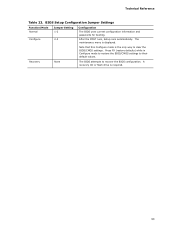
... to their default values. BIOS Setup Configuration Jumper Settings Function/Mode Normal Configure Jumper Setting 1-2 2-3 Configuration The BIOS uses current configuration information and passwords for booting. Technical Reference Table 23. Note that this Configure mode is displayed. After the POST runs, Setup runs automatically. A recovery CD or flash drive is required...
... to their default values. BIOS Setup Configuration Jumper Settings Function/Mode Normal Configure Jumper Setting 1-2 2-3 Configuration The BIOS uses current configuration information and passwords for booting. Technical Reference Table 23. Note that this Configure mode is displayed. After the POST runs, Setup runs automatically. A recovery CD or flash drive is required...
Product Specification
Page 61
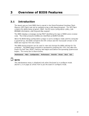
... 61 The menu bar is accessed by pressing the key after the Power-On Self-Test (POST) memory test begins and before the operating system boot begins. Section 2.3 on page 52 shows how to view and change the BIOS settings for the computer. The BIOS displays a message during POST ...identifying the type of BIOS Features 3.1 Introduction The board uses an Intel BIOS that is stored in the Serial Peripheral Interface Flash Memory (SPI Flash) and can be updated using a disk-based program. The initial production...
... 61 The menu bar is accessed by pressing the key after the Power-On Self-Test (POST) memory test begins and before the operating system boot begins. Section 2.3 on page 52 shows how to view and change the BIOS settings for the computer. The BIOS displays a message during POST ...identifying the type of BIOS Features 3.1 Introduction The board uses an Intel BIOS that is stored in the Serial Peripheral Interface Flash Memory (SPI Flash) and can be updated using a disk-based program. The initial production...
Product Specification
Page 62
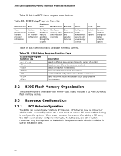
Intel Desktop Board DP67BG Technical Product Specification Table 28 lists the BIOS Setup program menu features. BIOS Setup Program Function Keys BIOS Setup Program Function Key Description or or ... advanced features available through the chipset Configures Memory, Bus and Processor overrides Sets passwords and security features Configures power management features and power supply controls Boot Selects boot options Exit Saves or discards changes to configure the system. When a user turns on the system after adding a PCI card, the BIOS automatically configures...
Intel Desktop Board DP67BG Technical Product Specification Table 28 lists the BIOS Setup program menu features. BIOS Setup Program Function Keys BIOS Setup Program Function Key Description or or ... advanced features available through the chipset Configures Memory, Bus and Processor overrides Sets passwords and security features Configures power management features and power supply controls Boot Selects boot options Exit Saves or discards changes to configure the system. When a user turns on the system after adding a PCI card, the BIOS automatically configures...

Product Specification
Page 64
...Both utilities verify that location/device. Intel Desktop Board DP67BG Technical Product Specification To install an ...be updated from a file on the Intel World Wide Web site: • Intel® Express BIOS Update utility, which requires booting from the file location on the Web. • Intel® Flash Memory Update Utility, which ...set to prevent accidentally installing an incompatible BIOS. For information about BIOS update utilities Refer to http://support.intel.com/support/motherboards/desktop/sb /CS-022312.htm. 3.6.1 Language Support The BIOS Setup program and help ...
...Both utilities verify that location/device. Intel Desktop Board DP67BG Technical Product Specification To install an ...be updated from a file on the Intel World Wide Web site: • Intel® Express BIOS Update utility, which requires booting from the file location on the Web. • Intel® Flash Memory Update Utility, which ...set to prevent accidentally installing an incompatible BIOS. For information about BIOS update utilities Refer to http://support.intel.com/support/motherboards/desktop/sb /CS-022312.htm. 3.6.1 Language Support The BIOS Setup program and help ...


