Product Specification
Page 6
... Fan Header Current Capability 53 2.5.3 Add-in Board Considerations 53 2.6 Thermal Considerations 53 2.7 Reliability 56 2.8 Environmental 56 3 Overview of BIOS Features 3.1 Introduction 57 3.2 BIOS Flash Memory Organization 58 3.3 Resource Configuration 58 3.3.1 PCI Autoconfiguration 58 3.4 System Management BIOS (SMBIOS 59 3.5 Legacy USB Support 59 3.6 BIOS Updates 60 3.6.1 Language Support 60 3.6.2 Custom Splash Screen 61 3.7 BIOS Recovery 61 3.8 Boot Options 62 3.8.1 CD-ROM Boot 62 3.8.2 Network Boot 62 3.8.3 Booting Without Attached Devices 62 3.8.4 Changing the Default...
... Fan Header Current Capability 53 2.5.3 Add-in Board Considerations 53 2.6 Thermal Considerations 53 2.7 Reliability 56 2.8 Environmental 56 3 Overview of BIOS Features 3.1 Introduction 57 3.2 BIOS Flash Memory Organization 58 3.3 Resource Configuration 58 3.3.1 PCI Autoconfiguration 58 3.4 System Management BIOS (SMBIOS 59 3.5 Legacy USB Support 59 3.6 BIOS Updates 60 3.6.1 Language Support 60 3.6.2 Custom Splash Screen 61 3.7 BIOS Recovery 61 3.8 Boot Options 62 3.8.1 CD-ROM Boot 62 3.8.2 Network Boot 62 3.8.3 Booting Without Attached Devices 62 3.8.4 Changing the Default...
Product Specification
Page 7
... Chassis (4-Pin) Fan Headers 42 18. Front Panel Header 45 21. Recommended Power Supply Current Values 52 25. Wake-up Devices and Events 28 9. System Memory Map 37 10. Processor Core Power Connector 43 19. Audio Jack Support 20 5. LAN Connector LED States 23 6. Power States and Targeted System Power 27 8. Front Panel Audio Header for a Two-Color Power LED 46 23. Supported Memory Configurations 15 4. States for Intel HD Audio 41 13. Contents Figures 1 Major Board Components 11 2 Block Diagram 13 3 Memory Channel and DIMM Configuration...
... Chassis (4-Pin) Fan Headers 42 18. Front Panel Header 45 21. Recommended Power Supply Current Values 52 25. Wake-up Devices and Events 28 9. System Memory Map 37 10. Processor Core Power Connector 43 19. Audio Jack Support 20 5. LAN Connector LED States 23 6. Power States and Targeted System Power 27 8. Front Panel Audio Header for a Two-Color Power LED 46 23. Supported Memory Configurations 15 4. States for Intel HD Audio 41 13. Contents Figures 1 Major Board Components 11 2 Block Diagram 13 3 Memory Channel and DIMM Configuration...
Product Specification
Page 8
... POST Codes 70 38. BIOS Beep Codes 67 34. Boot Device Menu Options 62 32. Front-panel Power LED Blink Codes 68 35. Typical Port 80h POST Sequence 73 39. BIOS Setup Program Function Keys 58 30. Supervisor and User Password Functions 64 33. Port 80h POST Code Ranges 69 37. EMC Regulations 81 42. Safety Standards 75 40. Intel Desktop Board DP55WB Technical Product Specification 26. Product Certification Markings 82 viii Acceptable Drives/Media Types for Components 55 27. Lead-Free Board...
... POST Codes 70 38. BIOS Beep Codes 67 34. Boot Device Menu Options 62 32. Front-panel Power LED Blink Codes 68 35. Typical Port 80h POST Sequence 73 39. BIOS Setup Program Function Keys 58 30. Supervisor and User Password Functions 64 33. Port 80h POST Code Ranges 69 37. EMC Regulations 81 42. Safety Standards 75 40. Intel Desktop Board DP55WB Technical Product Specification 26. Product Certification Markings 82 viii Acceptable Drives/Media Types for Components 55 27. Lead-Free Board...
Product Specification
Page 9
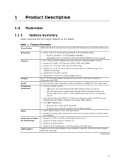
... using the Realtek* ALC888-VC2-GR audio codec • Fourteen USB 2.0 ports: ― Eight ports are implemented with stacked back panel connectors ― Six front panel ports implemented through Intel P55 Express Chipset with Intel Matrix Storage Technology RAID support • Two IEEE 1394a ports: ― One port via a back panel connector ― One port via an internal header for front panel cabling • Intel® BIOS resident in an LGA1156 socket ― One PCI Express* 2.0 x16 Graphics interface ― Integrated memory controller with dual channel DDR3 memory support...
... using the Realtek* ALC888-VC2-GR audio codec • Fourteen USB 2.0 ports: ― Eight ports are implemented with stacked back panel connectors ― Six front panel ports implemented through Intel P55 Express Chipset with Intel Matrix Storage Technology RAID support • Two IEEE 1394a ports: ― One port via a back panel connector ― One port via an internal header for front panel cabling • Intel® BIOS resident in an LGA1156 socket ― One PCI Express* 2.0 x16 Graphics interface ― Integrated memory controller with dual channel DDR3 memory support...
Product Specification
Page 14
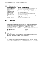
... DP55WB Supported processors Chipset information BIOS and driver updates Tested memory Integration information Visit this board. 14 Intel Desktop Board DP55WB Desktop Board Support Available configurations for information on the web site above are only supported when falling within the wattage requirements of unsupported processors can damage the board, the processor, and the power supply. Use of the Intel Desktop Board DP55WB. The processors listed above . See the Intel web site listed below for providing power to support the Intel Core i7 and Core i5 processors in an LGA1156...
... DP55WB Supported processors Chipset information BIOS and driver updates Tested memory Integration information Visit this board. 14 Intel Desktop Board DP55WB Desktop Board Support Available configurations for information on the web site above are only supported when falling within the wattage requirements of unsupported processors can damage the board, the processor, and the power supply. Use of the Intel Desktop Board DP55WB. The processors listed above . See the Intel web site listed below for providing power to support the Intel Core i7 and Core i5 processors in an LGA1156...
Product Specification
Page 15
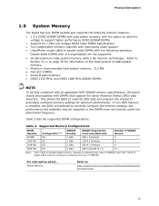
... configure memory settings for optimum performance. Product Description 1.5 System Memory The board has four DIMM sockets and supports the following memory features: • 1.5 V DDR3 SDRAM DIMMs with gold plated contacts, with the option to raise the voltage to support higher performance DDR3 SDRAM DIMMs. • Support for information on page 35 for 1.35V Low Voltage DDR3 (New JEDEC Specification) • Two independent memory channels with interleaved mode support...
... configure memory settings for optimum performance. Product Description 1.5 System Memory The board has four DIMM sockets and supports the following memory features: • 1.5 V DDR3 SDRAM DIMMs with gold plated contacts, with the option to raise the voltage to support higher performance DDR3 SDRAM DIMMs. • Support for information on page 35 for 1.35V Low Voltage DDR3 (New JEDEC Specification) • Two independent memory channels with interleaved mode support...
Product Specification
Page 16
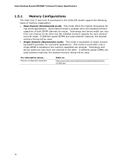
... the installed memory capacity for real world applications. This mode is used . For information about... Memory Configuration Examples Refer to the other . If different speed DIMMs are used between channels, the slowest memory timing will be equal. Technology and device width can vary from one channel to : http://www.intel.com/support/motherboards/desktop/sb/cs011965.htm 16 Intel Desktop Board DP55WB Technical Product Specification 1.5.1 Memory Configurations The Intel Core i7 and Core i5 processors in the LGA1156 socket support the following types of...
... the installed memory capacity for real world applications. This mode is used . For information about... Memory Configuration Examples Refer to the other . If different speed DIMMs are used between channels, the slowest memory timing will be equal. Technology and device width can vary from one channel to : http://www.intel.com/support/motherboards/desktop/sb/cs011965.htm 16 Intel Desktop Board DP55WB Technical Product Specification 1.5.1 Memory Configurations The Intel Core i7 and Core i5 processors in the LGA1156 socket support the following types of...
Product Specification
Page 19
... board provides six internal SATA connectors through the Intel P55 Express Chipset, which supports a master/slave configuration and two devices per channel. The SATA controller can be installed on each port for host to install separate RAID drivers using the Windows* XP and Windows Vista* and Windows* 7 operating systems. NOTE Many SATA drives use supported RAID features, you must first enable RAID in both AHCI and RAID without the need to device connections, unlike Parallel ATA (PATA) IDE which support one device per connector. In Native mode, standard PCI Conventional bus...
... board provides six internal SATA connectors through the Intel P55 Express Chipset, which supports a master/slave configuration and two devices per channel. The SATA controller can be installed on each port for host to install separate RAID drivers using the Windows* XP and Windows Vista* and Windows* 7 operating systems. NOTE Many SATA drives use supported RAID features, you must first enable RAID in both AHCI and RAID without the need to device connections, unlike Parallel ATA (PATA) IDE which support one device per connector. In Native mode, standard PCI Conventional bus...
Product Specification
Page 22
...; Intel P55 Express Chipset • RJ-45 LAN connector with integrated status LEDs Additional features of the LAN subsystem include: • CSMA/CD protocol engine • LAN connect interface between the PCH and the LAN controller • PCI Conventional bus power management ⎯ ACPI technology support ⎯ LAN wake capabilities • LAN subsystem software For information about LAN software and drivers Refer to http://downloadcenter.intel.com 1.9.1 Intel® 82578DC Gigabit Ethernet Controller The Intel 82578DC Gigabit Ethernet Controller supports the...
...; Intel P55 Express Chipset • RJ-45 LAN connector with integrated status LEDs Additional features of the LAN subsystem include: • CSMA/CD protocol engine • LAN connect interface between the PCH and the LAN controller • PCI Conventional bus power management ⎯ ACPI technology support ⎯ LAN wake capabilities • LAN subsystem software For information about LAN software and drivers Refer to http://downloadcenter.intel.com 1.9.1 Intel® 82578DC Gigabit Ethernet Controller The Intel 82578DC Gigabit Ethernet Controller supports the...
Product Specification
Page 26
... Power-on (ACPI G0 - Off (ACPI G2/G5 - working state) Soft-off/Standby (ACPI G1 - sleeping state) ...and the power switch is implemented at several levels, including: • Software support through Advanced Configuration and Power Interface (ACPI) • Hardware support: ⎯ Power connector ⎯ Fan headers ⎯ LAN wake capabilities ⎯ Instantly Available PC technology ⎯ Wake from USB ⎯ Power Management Event signal (PME#) wake-up (ACPI G0 - working state) Sleep (ACPI G1 - Intel Desktop Board DP55WB Technical Product Specification 1.11 Power...
... Power-on (ACPI G0 - Off (ACPI G2/G5 - working state) Soft-off/Standby (ACPI G1 - sleeping state) ...and the power switch is implemented at several levels, including: • Software support through Advanced Configuration and Power Interface (ACPI) • Hardware support: ⎯ Power connector ⎯ Fan headers ⎯ LAN wake capabilities ⎯ Instantly Available PC technology ⎯ Wake from USB ⎯ Power Management Event signal (PME#) wake-up (ACPI G0 - working state) Sleep (ACPI G1 - Intel Desktop Board DP55WB Technical Product Specification 1.11 Power...
Product Specification
Page 47
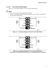
Connection Diagram for Front Panel USB Headers Figure 13. Connection Diagram for Front Panel USB Header (with Intel Z-U130 USB Solid-State Drive, or Compatible Device, Support) 47 NOTE • The +5 V DC power on the USB headers is a connection diagram for high-speed USB devices. Figure 12. Technical Reference 2.2.2.5 Front Panel USB Headers Figure 12 is fused. • Use only a front panel USB connector that conforms to the USB 2.0 specification for the front panel USB headers.
Connection Diagram for Front Panel USB Headers Figure 13. Connection Diagram for Front Panel USB Header (with Intel Z-U130 USB Solid-State Drive, or Compatible Device, Support) 47 NOTE • The +5 V DC power on the USB headers is a connection diagram for high-speed USB devices. Figure 12. Technical Reference 2.2.2.5 Front Panel USB Headers Figure 12 is fused. • Use only a front panel USB connector that conforms to the USB 2.0 specification for the front panel USB headers.
Product Specification
Page 57
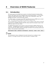
... configure mode and the computer is accessed by pressing the key after the Power-On Self-Test (POST) memory test begins and before the operating system boot begins. The BIOS displays a message during POST identifying the type of BIOS Features 3.1 Introduction The board uses an Intel BIOS that is stored in the Serial Peripheral Interface Flash Memory (SPI Flash) and can be updated using a disk-based program. The BIOS Setup program is powered-up, the BIOS compares the CPU version...
... configure mode and the computer is accessed by pressing the key after the Power-On Self-Test (POST) memory test begins and before the operating system boot begins. The BIOS displays a message during POST identifying the type of BIOS Features 3.1 Introduction The board uses an Intel BIOS that is stored in the Serial Peripheral Interface Flash Memory (SPI Flash) and can be updated using a disk-based program. The BIOS Setup program is powered-up, the BIOS compares the CPU version...
Product Specification
Page 58
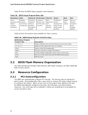
... a user insert or remove PCI cards without having to be onboard or add-in card. 58 BIOS Setup Program Menu Bar Maintenance Main Advanced Performance Security Clears passwords and displays processor information Displays processor and memory configuration Configures advanced features available through the chipset Configures Memory, Bus and Processor overrides Sets passwords and security features Power Configures power management features and power supply controls Boot Selects boot options Exit Saves or discards changes to Setup program options Table 29 lists the function keys...
... a user insert or remove PCI cards without having to be onboard or add-in card. 58 BIOS Setup Program Menu Bar Maintenance Main Advanced Performance Security Clears passwords and displays processor information Displays processor and memory configuration Configures advanced features available through the chipset Configures Memory, Bus and Processor overrides Sets passwords and security features Power Configures power management features and power supply controls Boot Selects boot options Exit Saves or discards changes to Setup program options Table 29 lists the function keys...
Product Specification
Page 62
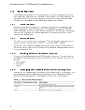
... to boot from a diskette drive, hard drive, USB drive, USB flash drive, CD-ROM, or the network. This menu displays the list of available boot devices (as set to the El Torito bootable CD-ROM format specification. This selection allows booting from the onboard LAN or a network add-in compliance to Full. 3.8.3 Booting Without Attached Devices For use this key during POST automatically forces booting from the selected device Exits the menu without saving changes 62 Intel Desktop Board DP55WB Technical Product Specification 3.8 Boot Options In the BIOS Setup program, the user...
... to boot from a diskette drive, hard drive, USB drive, USB flash drive, CD-ROM, or the network. This menu displays the list of available boot devices (as set to the El Torito bootable CD-ROM format specification. This selection allows booting from the onboard LAN or a network add-in compliance to Full. 3.8.3 Booting Without Attached Devices For use this key during POST automatically forces booting from the selected device Exits the menu without saving changes 62 Intel Desktop Board DP55WB Technical Product Specification 3.8 Boot Options In the BIOS Setup program, the user...
Product Specification
Page 65
Overview of BIOS Features 3.11 BIOS Performance Features The BIOS includes the following options to provide custom performance enhancements when using Intel Core i7 and Intel Core i5 processors in an LGA1156 socket. • Host Clock frequency adjustment • Processor multiplier adjustment (processor multiplier can only be adjusted down) • Processor voltage adjustment • Memory multiplier adjustment • Memory voltage adjustment • Uncore voltage adjustment 65
Overview of BIOS Features 3.11 BIOS Performance Features The BIOS includes the following options to provide custom performance enhancements when using Intel Core i7 and Intel Core i5 processors in an LGA1156 socket. • Host Clock frequency adjustment • Processor multiplier adjustment (processor multiplier can only be adjusted down) • Processor voltage adjustment • Memory multiplier adjustment • Memory voltage adjustment • Uncore voltage adjustment 65
Product Specification
Page 68
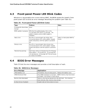
.... Replace the battery soon. Memory Size Decreased Memory size has decreased since the last boot. No Boot Device Available System did not find a device to reset values. CMOS memory may be accompanied by the following blink pattern: .25 seconds On, .25 seconds Off, .25 seconds On, .25 seconds Off. CMOS Checksum Bad The CMOS checksum is complete. Intel Desktop Board DP55WB Technical Product Specification 4.3 Front-panel Power LED Blink Codes Whenever a recoverable error occurs during POST...
.... Replace the battery soon. Memory Size Decreased Memory size has decreased since the last boot. No Boot Device Available System did not find a device to reset values. CMOS memory may be accompanied by the following blink pattern: .25 seconds On, .25 seconds Off, .25 seconds On, .25 seconds Off. CMOS Checksum Bad The CMOS checksum is complete. Intel Desktop Board DP55WB Technical Product Specification 4.3 Front-panel Power LED Blink Codes Whenever a recoverable error occurs during POST...
Product Specification
Page 69
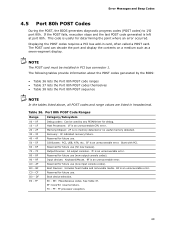
... Boot Devices: Includes fixed media and removable media. B0 - DF E0 - The POST card can decode the port and display the contents on a medium such as a seven-segment display. BF is left at port 80h. AF Reserved for future use (for future use. 50 - 5F I /O port 80h. D0 - See Table 37. F0 - Error Messages and Beep Codes 4.5 Port 80h POST Codes During the POST, the BIOS generates diagnostic progress codes (POST codes) to I /O Busses: PCI, USB, ATA...
... Boot Devices: Includes fixed media and removable media. B0 - DF E0 - The POST card can decode the port and display the contents on a medium such as a seven-segment display. BF is left at port 80h. AF Reserved for future use (for future use. 50 - 5F I /O port 80h. D0 - See Table 37. F0 - Error Messages and Beep Codes 4.5 Port 80h POST Codes During the POST, the BIOS generates diagnostic progress codes (POST codes) to I /O Busses: PCI, USB, ATA...

Product Specification
Page 71
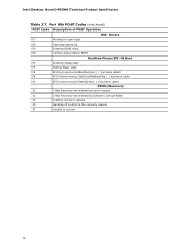
Error Messages and Beep Codes Table 37. Port 80h POST Codes (continued) POST Code Description of POST Operation Keyboard (USB) 90 Resetting keyboard 91 Disabling keyboard 92 Detecting presence of keyboard 93 Enabling the keyboard 94 Clearing keyboard input buffer 95 Instructing keyboard controller to run Self Test (PS/2 only) Mouse (USB) 98 Resetting mouse 99 Disabling mouse 9A Detecting presence of mouse 9B Enabling mouse Fixed Media B0 Resetting fixed media B1 Disabling fixed media B2 Detecting presence of a fixed media (hard drive detection etc...
Error Messages and Beep Codes Table 37. Port 80h POST Codes (continued) POST Code Description of POST Operation Keyboard (USB) 90 Resetting keyboard 91 Disabling keyboard 92 Detecting presence of keyboard 93 Enabling the keyboard 94 Clearing keyboard input buffer 95 Instructing keyboard controller to run Self Test (PS/2 only) Mouse (USB) 98 Resetting mouse 99 Disabling mouse 9A Detecting presence of mouse 9B Enabling mouse Fixed Media B0 Resetting fixed media B1 Disabling fixed media B2 Detecting presence of a fixed media (hard drive detection etc...
Product Specification
Page 72
Intel Desktop Board DP55WB Technical Product Specification Table 37. Port 80h POST Codes (continued) POST Code Description of POST Operation DXE Drivers E7 Waiting for user input E8 Checking password E9 Entering BIOS setup EB Calling Legacy Option ROMs Runtime Phase/EFI OS Boot F4 Entering Sleep state F5 Exiting Sleep state F8 EFI boot service ExitBootServices ( ) has been called F9 EFI runtime service SetVirtualAddressMap ( ) has been called FA EFI runtime service ResetSystem ( ) has been called PEIMs/Recovery 30 Crisis...
Intel Desktop Board DP55WB Technical Product Specification Table 37. Port 80h POST Codes (continued) POST Code Description of POST Operation DXE Drivers E7 Waiting for user input E8 Checking password E9 Entering BIOS setup EB Calling Legacy Option ROMs Runtime Phase/EFI OS Boot F4 Entering Sleep state F5 Exiting Sleep state F8 EFI boot service ExitBootServices ( ) has been called F9 EFI runtime service SetVirtualAddressMap ( ) has been called FA EFI runtime service ResetSystem ( ) has been called PEIMs/Recovery 30 Crisis...
Product Specification
Page 73
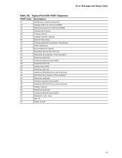
... a chipset component 22 Reading SPD from memory DIMMs 23 Detecting presence of memory DIMMs 25 Configuring memory 28 Testing memory 34 Loading recovery capsule E4 Entered DXE phase 12 Starting application processor initialization 13 SMM initialization 50 Enumerating PCI busses 51 Allocating resourced to PCI bus 92 Detecting the presence of the keyboard 90 Resetting keyboard 94 Clearing keyboard input buffer 95 Keyboard Self Test EB Calling Video BIOS 58 Resetting USB bus 5A Resetting PATA/SATA bus...
... a chipset component 22 Reading SPD from memory DIMMs 23 Detecting presence of memory DIMMs 25 Configuring memory 28 Testing memory 34 Loading recovery capsule E4 Entered DXE phase 12 Starting application processor initialization 13 SMM initialization 50 Enumerating PCI busses 51 Allocating resourced to PCI bus 92 Detecting the presence of the keyboard 90 Resetting keyboard 94 Clearing keyboard input buffer 95 Keyboard Self Test EB Calling Video BIOS 58 Resetting USB bus 5A Resetting PATA/SATA bus...


