

Technical Product Specification
Page 8
... Environmental 57 3 Overview of BIOS Features 3.1 Introduction 59 3.2 System Management BIOS (SMBIOS 61 3.3 Legacy USB Support 61 3.4 BIOS Updates 62 3.4.1 Language Support 62 3.4.2 Custom Splash Screen 63 3.5 BIOS Recovery 63 3.6 Boot Options 64 3.6.1 Optical Drive Boot 64 3.6.2 Network Boot 64 3.6.3 Booting Without Attached Devices 64 3.6.4 Changing the Default Boot Device During POST 64 4 Error Messages and Beep Codes 4.1 Speaker 65 4.2 BIOS Beep Codes 65 4.3 Front-panel Power LED Blink Codes 66 4.4 BIOS Error Messages 66 4.5 Port 80h POST Codes 67 5 Regulatory Compliance...
... Environmental 57 3 Overview of BIOS Features 3.1 Introduction 59 3.2 System Management BIOS (SMBIOS 61 3.3 Legacy USB Support 61 3.4 BIOS Updates 62 3.4.1 Language Support 62 3.4.2 Custom Splash Screen 63 3.5 BIOS Recovery 63 3.6 Boot Options 64 3.6.1 Optical Drive Boot 64 3.6.2 Network Boot 64 3.6.3 Booting Without Attached Devices 64 3.6.4 Changing the Default Boot Device During POST 64 4 Error Messages and Beep Codes 4.1 Speaker 65 4.2 BIOS Beep Codes 65 4.3 Front-panel Power LED Blink Codes 66 4.4 BIOS Error Messages 66 4.5 Port 80h POST Codes 67 5 Regulatory Compliance...
Technical Product Specification
Page 9
... and Fan Headers 28 7. Location of the Standby Power LED (Green 36 8. SATA Connectors 44 18. Components Shown in Figure 10 42 11. Wake-up Devices and Events 32 9. Main Power Connector 46 22. Back Panel Audio Connector Options 24 5. Back Panel Connectors 40 10. Connection Diagram for Front Panel USB Headers 49 13. Feature Summary 11 2. Supported Memory Configurations 18 4. TPM Header 43 12. LAN Connector LED States 26 6. Front Panel Header 47 23. Detailed System Memory Address Map 38 9. Localized High Temperature Zones...
... and Fan Headers 28 7. Location of the Standby Power LED (Green 36 8. SATA Connectors 44 18. Components Shown in Figure 10 42 11. Wake-up Devices and Events 32 9. Main Power Connector 46 22. Back Panel Audio Connector Options 24 5. Back Panel Connectors 40 10. Connection Diagram for Front Panel USB Headers 49 13. Feature Summary 11 2. Supported Memory Configurations 18 4. TPM Header 43 12. LAN Connector LED States 26 6. Front Panel Header 47 23. Detailed System Memory Address Map 38 9. Localized High Temperature Zones...
Technical Product Specification
Page 10
...-panel Power LED Blink Codes 66 36. Typical Port 80h POST Sequence 72 40. Boot Device Menu Options 64 34. Intel Desktop Board DH61SA Technical Product Specification 24. LPC Debug Header 49 25. Recommended Power Supply Current Values 53 27. BIOS Setup Program Menu Bar 60 31. BIOS Setup Program Function Keys 60 32. BIOS Error Messages 66 37. Fan Header Current Capability 54 28. Acceptable Drives/Media Types for Components 56 29. Port 80h POST Code Ranges 67 38. BIOS Setup Configuration Jumper Settings 51 26. Environmental Specifications...
...-panel Power LED Blink Codes 66 36. Typical Port 80h POST Sequence 72 40. Boot Device Menu Options 64 34. Intel Desktop Board DH61SA Technical Product Specification 24. LPC Debug Header 49 25. Recommended Power Supply Current Values 53 27. BIOS Setup Program Menu Bar 60 31. BIOS Setup Program Function Keys 60 32. BIOS Error Messages 66 37. Fan Header Current Capability 54 28. Acceptable Drives/Media Types for Components 56 29. Port 80h POST Code Ranges 67 38. BIOS Setup Configuration Jumper Settings 51 26. Environmental Specifications...

Technical Product Specification
Page 12
... back panel connectors ― Two USB 2.0 front panel ports are implemented through one dual-port internal header • Two SATA interfaces through the Intel H61 Express Chipset • One serial port header • One parallel port connector on the back panel • One PS/2* keyboard/mouse port on back panel Legacy I/O Control BIOS • Nuvoton* W83677HG-i Super I/O controller for hardware management and serial port, parallel port, and PS/2 support • Intel® BIOS resident in the SPI Flash device • Support for Advanced Configuration and Power Interface (ACPI), Plug...
... back panel connectors ― Two USB 2.0 front panel ports are implemented through one dual-port internal header • Two SATA interfaces through the Intel H61 Express Chipset • One serial port header • One parallel port connector on the back panel • One PS/2* keyboard/mouse port on back panel Legacy I/O Control BIOS • Nuvoton* W83677HG-i Super I/O controller for hardware management and serial port, parallel port, and PS/2 support • Intel® BIOS resident in the SPI Flash device • Support for Advanced Configuration and Power Interface (ACPI), Plug...
Technical Product Specification
Page 16
... for the Intel Desktop Board DH61SA Visit this board. 16 Intel Desktop Board DH61SA Desktop Board Support Available configurations for the most up-to the processor. Use of unsupported processors can damage the board, the processor, and the power supply. NOTE This board has specific requirements for this World Wide Web site: http://www.intel.com/products/motherboard/index.htm http://www.intel.com/p/en_US/support?iid=hdr+support http://ark.intel.com Supported processors Chipset information BIOS and driver updates Tested memory Integration information...
... for the Intel Desktop Board DH61SA Visit this board. 16 Intel Desktop Board DH61SA Desktop Board Support Available configurations for the most up-to the processor. Use of unsupported processors can damage the board, the processor, and the power supply. NOTE This board has specific requirements for this World Wide Web site: http://www.intel.com/products/motherboard/index.htm http://www.intel.com/p/en_US/support?iid=hdr+support http://ark.intel.com Supported processors Chipset information BIOS and driver updates Tested memory Integration information...
Technical Product Specification
Page 17
... BIOS Setup program are provided for information on the processor warranty, refer to correctly configure the memory settings, but performance and reliability may be populated with 4 Gb memory technology). Product Description 1.5 Intel® H61 Express Chipset The Intel H61 Express Chipset consisting of the processor beyond its specifications. Refer to the processor and the USB, SATA, LPC, audio, network, display, and PCI Express. and (v) affect system data integrity. CAUTION 1.5 V is a centralized controller for optimum performance. Intel...
... BIOS Setup program are provided for information on the processor warranty, refer to correctly configure the memory settings, but performance and reliability may be populated with 4 Gb memory technology). Product Description 1.5 Intel® H61 Express Chipset The Intel H61 Express Chipset consisting of the processor beyond its specifications. Refer to the processor and the USB, SATA, LPC, audio, network, display, and PCI Express. and (v) affect system data integrity. CAUTION 1.5 V is a centralized controller for optimum performance. Intel...
Technical Product Specification
Page 18
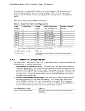
..., Intel Core i3, and Intel Pentium processors support the following types of SDRAM). This mode offers the highest throughput for real world applications. Tested Memory Refer to single channel bandwidth operation for real world applications. Technology and device width can vary from one channel to : http://www.intel.com/support/motherboards/desktop/sb/cs011965.htm 18 Intel Desktop Board DH61SA Technical Product Specification Intel assumes no responsibility that the memory installed on the desktop board, if used...
..., Intel Core i3, and Intel Pentium processors support the following types of SDRAM). This mode offers the highest throughput for real world applications. Tested Memory Refer to single channel bandwidth operation for real world applications. Technology and device width can vary from one channel to : http://www.intel.com/support/motherboards/desktop/sb/cs011965.htm 18 Intel Desktop Board DH61SA Technical Product Specification Intel assumes no responsibility that the memory installed on the desktop board, if used...

Technical Product Specification
Page 25
... support [Low Power Idle (LPI) mode] • Dual interconnect between the PCH and the LAN controller • PCI Conventional bus power management ACPI technology support LAN wake capabilities • LAN subsystem software For information about Obtaining LAN software and drivers Refer to IEEE 802.3x flow control support • 802.1p and 802.1q • TCP, IP, and UDP checksum offload (for IPv4 and IPv6) • Full device driver compatibility 1.12.2 LAN Subsystem Software LAN software...
... support [Low Power Idle (LPI) mode] • Dual interconnect between the PCH and the LAN controller • PCI Conventional bus power management ACPI technology support LAN wake capabilities • LAN subsystem software For information about Obtaining LAN software and drivers Refer to IEEE 802.3x flow control support • 802.1p and 802.1q • TCP, IP, and UDP checksum offload (for IPv4 and IPv6) • Full device driver compatibility 1.12.2 LAN Subsystem Software LAN software...

Technical Product Specification
Page 30
... - sleeping state) On (ACPI G0 - The use of ACPI with an ACPI-aware operating system. Intel Desktop Board DH61SA Technical Product Specification 1.16 Power Management Power management is implemented at several levels, including: • Software support through Advanced Configuration and Power Interface (ACPI) • Hardware support: Power connector Fan headers LAN wake capabilities Instantly Available PC technology Wake from PS/2 1.16.1 ACPI ACPI gives the operating system direct control over the power management and Plug and...
... - sleeping state) On (ACPI G0 - The use of ACPI with an ACPI-aware operating system. Intel Desktop Board DH61SA Technical Product Specification 1.16 Power Management Power management is implemented at several levels, including: • Software support through Advanced Configuration and Power Interface (ACPI) • Hardware support: Power connector Fan headers LAN wake capabilities Instantly Available PC technology Wake from PS/2 1.16.1 ACPI ACPI gives the operating system direct control over the power management and Plug and...
Technical Product Specification
Page 49
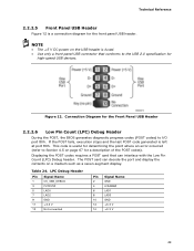
Connection Diagram for high-speed USB devices. The POST card can interface with the Low Pin Count (LPC) Debug header. If the POST fails, execution stops and the last POST code generated is useful for determining the point where an error occurred (refer to I/O port 80h. NOTE • The +5 V DC power on the USB header is a connection diagram for a description of the POST codes). Table 24. LPC Debug Header Pin Signal Name 1 CK_33M_DEBUG 3 PLTRST# 5 LAD0 7 LAD2...
Connection Diagram for high-speed USB devices. The POST card can interface with the Low Pin Count (LPC) Debug header. If the POST fails, execution stops and the last POST code generated is useful for determining the point where an error occurred (refer to I/O port 80h. NOTE • The +5 V DC power on the USB header is a connection diagram for a description of the POST codes). Table 24. LPC Debug Header Pin Signal Name 1 CK_33M_DEBUG 3 PLTRST# 5 LAD0 7 LAD2...
Technical Product Specification
Page 59
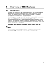
... and change the BIOS settings for the computer. The BIOS Setup program can be used to put the board in configure mode. 59 Maintenance Main Configuration Performance Security Power Boot Exit NOTE The maintenance menu is displayed only when the board is in configure mode. 3 Overview of BIOS Features 3.1 Introduction The board uses an Intel BIOS that is stored in a 32 Mbit (8.192 KB) Serial Peripheral Interface Flash Memory (SPI Flash) device which can be updated using a set of BIOS and a revision code.
... and change the BIOS settings for the computer. The BIOS Setup program can be used to put the board in configure mode. 59 Maintenance Main Configuration Performance Security Power Boot Exit NOTE The maintenance menu is displayed only when the board is in configure mode. 3 Overview of BIOS Features 3.1 Introduction The board uses an Intel BIOS that is stored in a 32 Mbit (8.192 KB) Serial Peripheral Interface Flash Memory (SPI Flash) device which can be updated using a set of BIOS and a revision code.

Technical Product Specification
Page 60
Intel Desktop Board DH61SA Technical Product Specification Table 30 lists the BIOS Setup program menu features. tion Performance Configures advanced features available through the chipset Configures memory, bus and processor overrides Security Sets passwords and security features Power Configures power management features and power supply controls Boot Selects boot options Exit Saves or discards changes to Setup program options Table 31 lists the function keys available for the current menu Save the current values and exits the BIOS Setup program Exits the menu 60 Table 31...
Intel Desktop Board DH61SA Technical Product Specification Table 30 lists the BIOS Setup program menu features. tion Performance Configures advanced features available through the chipset Configures memory, bus and processor overrides Security Sets passwords and security features Power Configures power management features and power supply controls Boot Selects boot options Exit Saves or discards changes to Setup program options Table 31 lists the function keys available for the current menu Save the current values and exits the BIOS Setup program Exits the menu 60 Table 31...
Technical Product Specification
Page 66
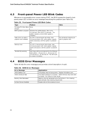
... power. BIOS Error Messages Error Message CMOS Battery Low CMOS Checksum Bad Memory Size Decreased No Boot Device Available Explanation The battery may have been corrupted. System did not find a device to reset values. Memory size has decreased since the last boot. If no add-in graphics card 4.4 BIOS Error Messages Table 36 lists the error messages and provides a brief description of 16 blinks. Intel Desktop Board DH61SA Technical Product Specification 4.3 Front-panel Power LED Blink Codes Whenever a recoverable error occurs during POST, the BIOS...
... power. BIOS Error Messages Error Message CMOS Battery Low CMOS Checksum Bad Memory Size Decreased No Boot Device Available Explanation The battery may have been corrupted. System did not find a device to reset values. Memory size has decreased since the last boot. If no add-in graphics card 4.4 BIOS Error Messages Table 36 lists the error messages and provides a brief description of 16 blinks. Intel Desktop Board DH61SA Technical Product Specification 4.3 Front-panel Power LED Blink Codes Whenever a recoverable error occurs during POST, the BIOS...
Technical Product Specification
Page 67
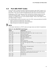
.... The POST card can interface with PCI. For future use Input devices: Keyboard/Mouse. For future use For future use 67 Resuming from SX states. 0x10 -0x20 - Start with the Low Pin Count (LPC) Debug header. If the POST fails, execution stops and the last POST code generated is left at this point. Error Messages and Beep Codes 4.5 Port 80h POST Codes During the POST, the BIOS generates diagnostic progress codes (POST codes) to I /O buses: PCI, USB...
.... The POST card can interface with PCI. For future use Input devices: Keyboard/Mouse. For future use For future use 67 Resuming from SX states. 0x10 -0x20 - Start with the Low Pin Count (LPC) Debug header. If the POST fails, execution stops and the last POST code generated is left at this point. Error Messages and Beep Codes 4.5 Port 80h POST Codes During the POST, the BIOS generates diagnostic progress codes (POST codes) to I /O buses: PCI, USB...

DH61SA Specification Update
Page 6
... recognized or function when plugged into any PCI slot on the Intel® 6 Series Chipset. No Fix: There are used in the table: Doc: Document change or update that do not support PCI add in cards that apply to fix this erratum. Status: This problem may be implemented. The following table indicates the Specification Changes, Errata, Specification Clarifications, or Documentation Changes that utilize a PCI Express to PCI bridge component included in...
... recognized or function when plugged into any PCI slot on the Intel® 6 Series Chipset. No Fix: There are used in the table: Doc: Document change or update that do not support PCI add in cards that apply to fix this erratum. Status: This problem may be implemented. The following table indicates the Specification Changes, Errata, Specification Clarifications, or Documentation Changes that utilize a PCI Express to PCI bridge component included in...

English Product Guide
Page 3
... Intel® Desktop Board DH61SA. NOTE Notes call attention to install the Desktop Board and other environments, such as medical, industrial, alarm systems, test equipment, etc. Use Only for Intended Applications All Intel Desktop Boards are evaluated as follows: 1 Desktop Board Features: a summary of product features 2 Installing and Replacing Desktop Board Components: instructions on how to update the BIOS A Error Messages and Indicators: information about BIOS error messages and beep codes B Regulatory Compliance: describes the board...
... Intel® Desktop Board DH61SA. NOTE Notes call attention to install the Desktop Board and other environments, such as medical, industrial, alarm systems, test equipment, etc. Use Only for Intended Applications All Intel Desktop Boards are evaluated as follows: 1 Desktop Board Features: a summary of product features 2 Installing and Replacing Desktop Board Components: instructions on how to update the BIOS A Error Messages and Indicators: information about BIOS error messages and beep codes B Regulatory Compliance: describes the board...
English Product Guide
Page 5
... Processor ...14 Intel® H61 Express Chipset 15 Main Memory...15 Graphics Subsystem 16 Integrated Graphics 16 Analog Display (VGA 16 Audio Subsystem 16 LAN Subsystem 17 USB Support ...17 SATA Support...18 Expandability...18 Legacy I/O ...18 BIOS ...18 SATA Auto Configuration 18 PCI*/PCI Express Auto Configuration 19 BIOS Security Passwords 19 Trusted Platform Module (TPM) Support 19 Fan Speed Control and Hardware Monitoring 20 Power Management 20 Software Support 20 Hardware Support 21 Onboard Speaker 24 Real-Time Clock Subsystem 25 2 Installing and Replacing Desktop Board...
... Processor ...14 Intel® H61 Express Chipset 15 Main Memory...15 Graphics Subsystem 16 Integrated Graphics 16 Analog Display (VGA 16 Audio Subsystem 16 LAN Subsystem 17 USB Support ...17 SATA Support...18 Expandability...18 Legacy I/O ...18 BIOS ...18 SATA Auto Configuration 18 PCI*/PCI Express Auto Configuration 19 BIOS Security Passwords 19 Trusted Platform Module (TPM) Support 19 Fan Speed Control and Hardware Monitoring 20 Power Management 20 Software Support 20 Hardware Support 21 Onboard Speaker 24 Real-Time Clock Subsystem 25 2 Installing and Replacing Desktop Board...
English Product Guide
Page 6
... Desktop Board DH61SA Product Guide TPM Header 43 Front Panel Header 44 Serial Port Header 44 Front Panel USB 2.0 Header 45 Connecting to the Audio System 46 Connecting Chassis Fan and Power Supply Cables 47 Connecting a Chassis Fan Cable 47 Connecting Power Supply Cables 48 Setting the BIOS Configuration Jumper 49 Clearing Passwords in the BIOS Setup Program 50 Replacing the Battery 51 3 Updating the BIOS Updating the BIOS with the Intel® Express BIOS Update Utility 57 Updating the BIOS Using the F7 Function Key 58 Updating the BIOS with the Intel® Flash Memory Update...
... Desktop Board DH61SA Product Guide TPM Header 43 Front Panel Header 44 Serial Port Header 44 Front Panel USB 2.0 Header 45 Connecting to the Audio System 46 Connecting Chassis Fan and Power Supply Cables 47 Connecting a Chassis Fan Cable 47 Connecting Power Supply Cables 48 Setting the BIOS Configuration Jumper 49 Clearing Passwords in the BIOS Setup Program 50 Replacing the Battery 51 3 Updating the BIOS Updating the BIOS with the Intel® Express BIOS Update Utility 57 Updating the BIOS Using the F7 Function Key 58 Updating the BIOS with the Intel® Flash Memory Update...

English Product Guide
Page 18
...SATA Auto Configuration If you install a SATA device (such as a hard disk drive) in your computer, the autoconfiguration utility in the Serial Peripheral Interface (SPI) Flash memory device. You can be updated by specifying manual configuration in Chapter 3 starting on the back panel • Serial IRQ interface compatible with serialized IRQ support for Conventional PCI bus systems • Intelligent power management, including a programmable wake-up event interface • Conventional PCI bus power management support The BIOS Setup program provides configuration options for the Legacy...
...SATA Auto Configuration If you install a SATA device (such as a hard disk drive) in your computer, the autoconfiguration utility in the Serial Peripheral Interface (SPI) Flash memory device. You can be updated by specifying manual configuration in Chapter 3 starting on the back panel • Serial IRQ interface compatible with serialized IRQ support for Conventional PCI bus systems • Intelligent power management, including a programmable wake-up event interface • Conventional PCI bus power management support The BIOS Setup program provides configuration options for the Legacy...
English Product Guide
Page 50
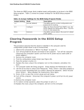
.... 11. Jumper Settings for the BIOS Setup Program Modes Jumper Setting Mode 1-2 Normal (default) 2-3 Configure None Recovery Description The BIOS uses the current configuration and passwords for the BIOS Setup program modes. Table 12. Select Yes and press . Disconnect the computer's power cord from the AC power source (wall outlet or power adapter). 3. Intel Desktop Board DH61SA Product Guide The three-pin BIOS jumper block enables board configuration to clear passwords. After the Power-On Self-Test (POST) runs, the BIOS displays the Maintenance Menu. Use this menu to be...
.... 11. Jumper Settings for the BIOS Setup Program Modes Jumper Setting Mode 1-2 Normal (default) 2-3 Configure None Recovery Description The BIOS uses the current configuration and passwords for the BIOS Setup program modes. Table 12. Select Yes and press . Disconnect the computer's power cord from the AC power source (wall outlet or power adapter). 3. Intel Desktop Board DH61SA Product Guide The three-pin BIOS jumper block enables board configuration to clear passwords. After the Power-On Self-Test (POST) runs, the BIOS displays the Maintenance Menu. Use this menu to be...


