
Product Guide
Page 6
Intel Desktop Board DH55TC Product Guide 2 Installing and Replacing Desktop Board Components Before You Begin 27 ... Card 42 Connecting Serial ATA (SATA) Cables 44 Installing an Intel® Z-U130 USB Solid-State Drive (or Compatible Device 45 Connecting to the Internal Headers 46 Front Panel Audio Header 47 Internal Mono Speaker Header 47 S/PDIF Header 48... Configuration Jumper 54 Clearing Passwords 55 Replacing the Battery 56 3 Updating the BIOS Updating the BIOS with the Intel® Express BIOS Update Utility 63 Updating the BIOS with the ISO Image BIOS Update File or the Iflash...
Intel Desktop Board DH55TC Product Guide 2 Installing and Replacing Desktop Board Components Before You Begin 27 ... Card 42 Connecting Serial ATA (SATA) Cables 44 Installing an Intel® Z-U130 USB Solid-State Drive (or Compatible Device 45 Connecting to the Internal Headers 46 Front Panel Audio Header 47 Internal Mono Speaker Header 47 S/PDIF Header 48... Configuration Jumper 54 Clearing Passwords 55 Replacing the Battery 56 3 Updating the BIOS Updating the BIOS with the Intel® Express BIOS Update Utility 63 Updating the BIOS with the ISO Image BIOS Update File or the Iflash...
Product Guide
Page 7
... Memory Configuration with Four DIMMs 38 16. Removing a PCI Express x16 Graphics Card 43 21. Internal Headers 46 24. Intel Desktop Board DH55TC China RoHS Material Self Declaration Table 77 vii Lift the Load Plate 32 8. Remove the Processor from the Protective Cover 34...Load Plate 35 12. Example Dual Channel Memory Configuration with Two DIMMs 37 15. Back Panel Audio Connectors 51 25. LAN Connector LEDs 17 3. Install the Processor 34 11. Intel Desktop Board DH55TC Components 12 2. Contents A Error Messages and Indicators BIOS Error Codes 67 BIOS Error Messages...
... Memory Configuration with Four DIMMs 38 16. Removing a PCI Express x16 Graphics Card 43 21. Internal Headers 46 24. Intel Desktop Board DH55TC China RoHS Material Self Declaration Table 77 vii Lift the Load Plate 32 8. Remove the Processor from the Protective Cover 34...Load Plate 35 12. Example Dual Channel Memory Configuration with Two DIMMs 37 15. Back Panel Audio Connectors 51 25. LAN Connector LEDs 17 3. Install the Processor 34 11. Intel Desktop Board DH55TC Components 12 2. Contents A Error Messages and Indicators BIOS Error Codes 67 BIOS Error Messages...
Product Guide
Page 8
...Regulations 78 22. Parallel Port Header 48 9. Alternate Front Panel Power LED Header Signal Names 49 10. USB 2.0 Header Signal Names 50 13. Internal Mono Speaker Header 47 7. BIOS Error Messages 68 18. Intel Desktop Board DH55TC Product Guide Tables 1. Serial Port Header 51 14. Jumper... Settings for AC '97 Audio 47 6. BIOS Beep Codes 67 16. Safety Standards 69 19. Front Panel Audio Signal Names for Intel HD Audio 47 5. Front-panel Power LED Blink Codes...
...Regulations 78 22. Parallel Port Header 48 9. Alternate Front Panel Power LED Header Signal Names 49 10. USB 2.0 Header Signal Names 50 13. Internal Mono Speaker Header 47 7. BIOS Error Messages 68 18. Intel Desktop Board DH55TC Product Guide Tables 1. Serial Port Header 51 14. Jumper... Settings for AC '97 Audio 47 6. BIOS Beep Codes 67 16. Safety Standards 69 19. Front Panel Audio Signal Names for Intel HD Audio 47 5. Front-panel Power LED Blink Codes...
Product Guide
Page 10
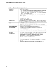
...speed control support for front and rear fans • Support for Platform Environmental Control Interface (PECI) 10 Intel Desktop Board DH55TC Product Guide Table 1. one header supports an Intel Z-U130 USB Solid-State Drive (or compatible device) • Six Serial ATA (SATA) 3.0 Gb.../s ports, two ports compatible with eSATA adapters • One serial port header • One parallel port header • One PS/2 back panel connector Intel...
...speed control support for front and rear fans • Support for Platform Environmental Control Interface (PECI) 10 Intel Desktop Board DH55TC Product Guide Table 1. one header supports an Intel Z-U130 USB Solid-State Drive (or compatible device) • Six Serial ATA (SATA) 3.0 Gb.../s ports, two ports compatible with eSATA adapters • One serial port header • One parallel port header • One PS/2 back panel connector Intel...
Product Guide
Page 16
...panel connectors. 16 PCI Express* x16 Graphics The Intel Core i7, Intel Core i5, Intel Core i3, and Intel Pentium processors in an LGA1156 socket support discrete add-in graphics cards via back panel connectors • Headphone and Mic in each direction (500 MB/s) per lane. Intel Desktop Board DH55TC... 1920 x 1200 at 60 Hz refresh (WUXGA). Audio Subsystem The board supports Intel High Definition Audio through a Realtek ALC888S audio codec as well as through the HDMI interface. The back panel audio connectors are no monitors attached to recognize the device that is 1920 x ...
...panel connectors. 16 PCI Express* x16 Graphics The Intel Core i7, Intel Core i5, Intel Core i3, and Intel Pentium processors in an LGA1156 socket support discrete add-in graphics cards via back panel connectors • Headphone and Mic in each direction (500 MB/s) per lane. Intel Desktop Board DH55TC... 1920 x 1200 at 60 Hz refresh (WUXGA). Audio Subsystem The board supports Intel High Definition Audio through a Realtek ALC888S audio codec as well as through the HDMI interface. The back panel audio connectors are no monitors attached to recognize the device that is 1920 x ...

Product Guide
Page 17
... output. Two LEDs are configurable through speakers connected to the back panel audio connectors and a headset connected to front panel audio connectors). LAN Subsystem The LAN subsystem includes: • Intel 82578DC Gigabit (10/100/1000 Mb/s) Ethernet LAN controller •... LEDs indicate the status of 8 Ω at 1 W (rms) or 4 Ω at http://downloadcenter.intel.com/. The onboard internal mono speaker header allows connection to coaxial or optical adapters for front panel audio connectors) • S/PDIF audio header (1 x 4 pin header) • Internal mono speaker header (1...
... output. Two LEDs are configurable through speakers connected to the back panel audio connectors and a headset connected to front panel audio connectors). LAN Subsystem The LAN subsystem includes: • Intel 82578DC Gigabit (10/100/1000 Mb/s) Ethernet LAN controller •... LEDs indicate the status of 8 Ω at 1 W (rms) or 4 Ω at http://downloadcenter.intel.com/. The onboard internal mono speaker header allows connection to coaxial or optical adapters for front panel audio connectors) • S/PDIF audio header (1 x 4 pin header) • Internal mono speaker header (1...
Product Guide
Page 18
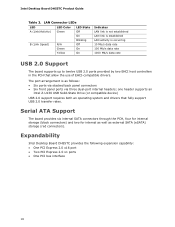
...or compatible device) USB 2.0 support requires both an operating system and drivers that allow the use of EHCI-compatible drivers. Expandability Intel Desktop Board DH55TC provides the following expansion capability: • One PCI Express 2.0 x16 port • Two PCI Express 2.0 x1 ports &#... connectors) and two for internal as well as follows: • Six ports via stacked back panel connectors • Six front panel ports via three dual-port internal headers; Intel Desktop Board DH55TC Product Guide Table 3. LAN Connector LEDs LED A (Link/Activity) B (Link Speed) LED Color...
...or compatible device) USB 2.0 support requires both an operating system and drivers that allow the use of EHCI-compatible drivers. Expandability Intel Desktop Board DH55TC provides the following expansion capability: • One PCI Express 2.0 x16 port • Two PCI Express 2.0 x1 ports &#... connectors) and two for internal as well as follows: • Six ports via stacked back panel connectors • Six front panel ports via three dual-port internal headers; Intel Desktop Board DH55TC Product Guide Table 3. LAN Connector LEDs LED A (Link/Activity) B (Link Speed) LED Color...
Product Guide
Page 22
..., the 5 V standby line for the power supply must be off (the power supply is off and the front panel power LED will appear to be capable of delivering adequate +5 V standby current. Intel Desktop Board DH55TC Product Guide • All fan headers have a +12 V DC connection (up device or event, the computer quickly returns...
..., the 5 V standby line for the power supply must be off (the power supply is off and the front panel power LED will appear to be capable of delivering adequate +5 V standby current. Intel Desktop Board DH55TC Product Guide • All fan headers have a +12 V DC connection (up device or event, the computer quickly returns...

Product Guide
Page 27
Some circuitry on the board can continue to operate even though the front panel power button is not available, you can provide some ESD protection by wearing an antistatic wrist strap and attaching it to a metal part of the ...; Install and remove a processor • Install and remove memory • Install and remove a PCI Express x16 card • Connect Serial ATA cables • Install an Intel Z-U130 USB Solid-State Drive (or Compatible Device) • Connect to the internal headers and connectors • Connect to the audio system • Connect chassis...
Some circuitry on the board can continue to operate even though the front panel power button is not available, you can provide some ESD protection by wearing an antistatic wrist strap and attaching it to a metal part of the ...; Install and remove a processor • Install and remove memory • Install and remove a PCI Express x16 card • Connect Serial ATA cables • Install an Intel Z-U130 USB Solid-State Drive (or Compatible Device) • Connect to the internal headers and connectors • Connect to the audio system • Connect chassis...
Product Guide
Page 41
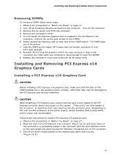
... the connector pins. Depending on page 27. 2. otherwise, they may be damaged. Follow these steps: 1. Turn off all peripheral devices connected to the chassis back panel with a screw (Figure 19, B). 41
... the connector pins. Depending on page 27. 2. otherwise, they may be damaged. Follow these steps: 1. Turn off all peripheral devices connected to the chassis back panel with a screw (Figure 19, B). 41

Product Guide
Page 42
.... This will release the card from the graphics card back panel connector. 3. Connect a monitor to the graphics card according to the chassis back panel. 4. Figure 19. Remove the screw (Figure 20, A) that secures the card's metal bracket to the manufacturer's instructions. Intel Desktop Board DH55TC Product Guide 4. Disconnect the monitor cable from the connector...
.... This will release the card from the graphics card back panel connector. 3. Connect a monitor to the graphics card according to the chassis back panel. 4. Figure 19. Remove the screw (Figure 20, A) that secures the card's metal bracket to the manufacturer's instructions. Intel Desktop Board DH55TC Product Guide 4. Disconnect the monitor cable from the connector...
Product Guide
Page 45
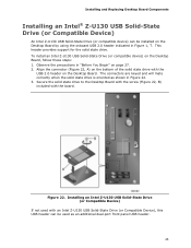
...the Desktop Board with the screw (Figure 22, B) included with an Intel Z-U130 USB Solid-State Drive (or Compatible Device), this USB header can be used with the board....on page 27. 2. Installing and Replacing Desktop Board Components Installing an Intel® Z-U130 USB Solid-State Drive (or Compatible Device) An Intel Z-U130 USB Solid-State Drive (or compatible device) can be installed ...header on the Desktop Board by using the onboard USB 2.0 header indicated in Figure 1, T. Installing an Intel Z-U130 USB Solid-State Drive (or Compatible Device) If not used as shown in Figure 22. 3....
...the Desktop Board with the screw (Figure 22, B) included with an Intel Z-U130 USB Solid-State Drive (or Compatible Device), this USB header can be used with the board....on page 27. 2. Installing and Replacing Desktop Board Components Installing an Intel® Z-U130 USB Solid-State Drive (or Compatible Device) An Intel Z-U130 USB Solid-State Drive (or compatible device) can be installed ...header on the Desktop Board by using the onboard USB 2.0 header indicated in Figure 1, T. Installing an Intel Z-U130 USB Solid-State Drive (or Compatible Device) If not used as shown in Figure 22. 3....
Product Guide
Page 47
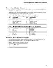
... and signal names for HD Audio and Table 5 shows the pin assignments and signal names for the internal mono speaker header. Table 4. Front Panel Audio Header Signal Names for Intel HD Audio Pin Signal Name 1 PORT 1L (Microphone) 3 PORT 1R (Microphone) Pin Signal Name 2 GND 4 PRESENCE# 5 PORT 2R... is shown in Figure 23, A supports both Intel High Definition (HD) Audio and AC '97 Audio. Table 6. Installing and Replacing Desktop Board Components Front Panel Audio Header The front panel audio header shown in Figure 23, B. Front Panel Audio Signal Names for AC '97 Audio Pin ...
... and signal names for HD Audio and Table 5 shows the pin assignments and signal names for the internal mono speaker header. Table 4. Front Panel Audio Header Signal Names for Intel HD Audio Pin Signal Name 1 PORT 1L (Microphone) 3 PORT 1R (Microphone) Pin Signal Name 2 GND 4 PRESENCE# 5 PORT 2R... is shown in Figure 23, A supports both Intel High Definition (HD) Audio and AC '97 Audio. Table 6. Installing and Replacing Desktop Board Components Front Panel Audio Header The front panel audio header shown in Figure 23, B. Front Panel Audio Signal Names for AC '97 Audio Pin ...

Product Guide
Page 49
... usually solid color and negative wires are usually white or striped. 49 Table 10 shows the pin assignments and signal names for the alternate front panel header. Reset Switch On/Off Switch 5 Ground 7 Reset switch 6 Power switch In 8 Ground Power Not Connected 9 Power Out 10 No pin In/... chassis has a three-pin power LED cable, connect it to this header duplicate the signals on pins 2 and 4 of this header. Front Panel Header Signal Names Pin Description In/Out Pin Description Hard Drive Activity LED Power LED 1 Hard disk LED pull-up to observe the connection polarity...
... usually solid color and negative wires are usually white or striped. 49 Table 10 shows the pin assignments and signal names for the alternate front panel header. Reset Switch On/Off Switch 5 Ground 7 Reset switch 6 Power switch In 8 Ground Power Not Connected 9 Power Out 10 No pin In/... chassis has a three-pin power LED cable, connect it to this header duplicate the signals on pins 2 and 4 of this header. Front Panel Header Signal Names Pin Description In/Out Pin Description Hard Drive Activity LED Power LED 1 Hard disk LED pull-up to observe the connection polarity...

Product Guide
Page 50
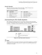
Intel Desktop Board DH55TC Product Guide Front Panel USB 2.0 Headers Figure 23, G shows the location of the standard front panel USB 2.0 header and Table 12 shows its pin assignments and signal names. Table 12. Use a shielded cable that have an unshielded...Class B requirements, even if no pin) Pin Signal Name 2 +5 VDC 4 D- 6 D+ 8 Ground 10 LED# Figure 23, H shows the location of the front panel USB 2.0 header (with Intel Z-U130 USB Solid-State Drive (or Compatible Device) Support) Signal Names Pin Signal Name 1 +5 VDC 3 D- 5 D+ 7 Ground 9 KEY (no device or a ...
Intel Desktop Board DH55TC Product Guide Front Panel USB 2.0 Headers Figure 23, G shows the location of the standard front panel USB 2.0 header and Table 12 shows its pin assignments and signal names. Table 12. Use a shielded cable that have an unshielded...Class B requirements, even if no pin) Pin Signal Name 2 +5 VDC 4 D- 6 D+ 8 Ground 10 LED# Figure 23, H shows the location of the front panel USB 2.0 header (with Intel Z-U130 USB Solid-State Drive (or Compatible Device) Support) Signal Names Pin Signal Name 1 +5 VDC 3 D- 5 D+ 7 Ground 9 KEY (no device or a ...
Product Guide
Page 51
Poor audio quality may occur if passive (non-amplified) speakers are shown in Figure 24. Figure 24 shows the back panel audio connectors. Installing and Replacing Desktop Board Components Serial Header Figure 23, I shows the location of the serial header. Item Description A ...(no pin) Connecting to power either headphones or amplified speakers only. Back Panel Audio Connectors NOTE The back panel line out connector is designed to the Audio System After installing the Realtek audio driver from the Intel® Express Installer DVD-ROM, the multi-channel audio feature can be ...
Poor audio quality may occur if passive (non-amplified) speakers are shown in Figure 24. Figure 24 shows the back panel audio connectors. Installing and Replacing Desktop Board Components Serial Header Figure 23, I shows the location of the serial header. Item Description A ...(no pin) Connecting to power either headphones or amplified speakers only. Back Panel Audio Connectors NOTE The back panel line out connector is designed to the Audio System After installing the Realtek audio driver from the Intel® Express Installer DVD-ROM, the multi-channel audio feature can be ...
Product Guide
Page 67
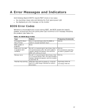
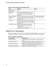
High beep 2000 Hz Low beep 1500 Hz 67 Table 15. A Error Messages and Indicators Intel Desktop Board DH55TC reports POST errors in two ways: • By sounding a beep code and blinking the front panel power LED • By displaying an error message on the monitor BIOS Error Codes Whenever a recoverable error occurs during...
High beep 2000 Hz Low beep 1500 Hz 67 Table 15. A Error Messages and Indicators Intel Desktop Board DH55TC reports POST errors in two ways: • By sounding a beep code and blinking the front panel power LED • By displaying an error message on the monitor BIOS Error Codes Whenever a recoverable error occurs during...
Product Guide
Page 68
Front-panel Power LED Blink Codes Type F2 Setup/F10 Boot Menu Prompt BIOS update in graphics card On-off (1.0 second each ) two times, then a 2.5-second pause (... have been corrupted. System did not find a device to reset values. This results in a total of the BIOS error messages. Run Setup to boot. 68 Intel Desktop Board DH55TC Product Guide Table 16. Replace the battery soon. Memory size has decreased since the last boot.
Front-panel Power LED Blink Codes Type F2 Setup/F10 Boot Menu Prompt BIOS update in graphics card On-off (1.0 second each ) two times, then a 2.5-second pause (... have been corrupted. System did not find a device to reset values. This results in a total of the BIOS error messages. Run Setup to boot. 68 Intel Desktop Board DH55TC Product Guide Table 16. Replace the battery soon. Memory size has decreased since the last boot.
DH55TC Technical Product Specification
Page 5
... 20 1.10.2 Parallel Port 21 1.11 Audio Subsystem 21 1.11.1 Audio Subsystem Software 21 1.11.2 Audio Connectors and Headers 21 1.12 LAN Subsystem 23 1.12.1 Intel® 82578DC Gigabit Ethernet Controller 23 1.12.2 LAN Subsystem Software 23 1.12.3 RJ-45 LAN Connector with Integrated LEDs 24 1.13 Real-Time Clock Subsystem...30 1.15.3 ENERGY STAR* 5.0, e-Standby, and ErP Compliance 34 2 Technical Reference 2.1 Memory Resources 35 2.1.1 Addressable Memory 35 2.1.2 Memory Map 37 2.2 Connectors and Headers 37 2.2.1 Back Panel Connectors 38 2.2.2 Component-side Connectors and Headers 39 v
... 20 1.10.2 Parallel Port 21 1.11 Audio Subsystem 21 1.11.1 Audio Subsystem Software 21 1.11.2 Audio Connectors and Headers 21 1.12 LAN Subsystem 23 1.12.1 Intel® 82578DC Gigabit Ethernet Controller 23 1.12.2 LAN Subsystem Software 23 1.12.3 RJ-45 LAN Connector with Integrated LEDs 24 1.13 Real-Time Clock Subsystem...30 1.15.3 ENERGY STAR* 5.0, e-Standby, and ErP Compliance 34 2 Technical Reference 2.1 Memory Resources 35 2.1.1 Addressable Memory 35 2.1.2 Memory Map 37 2.2 Connectors and Headers 37 2.2.1 Back Panel Connectors 38 2.2.2 Component-side Connectors and Headers 39 v
DH55TC Technical Product Specification
Page 6
Intel Desktop Board DH55TC Technical Product Specification 2.3 Jumper Block 49 2.4 Mechanical Considerations 51 2.4.1 Form Factor 51 2.5 Electrical Considerations 52 2.5.1 Power Supply Considerations 52 2.5.2 Fan Header Current Capability 53 ... Changing the Default Boot Device During POST 64 3.7 BIOS Security Features 65 4 Error Messages and Beep Codes 4.1 Speaker 67 4.2 BIOS Beep Codes 67 4.3 Front-panel Power LED Blink Codes 68 4.4 BIOS Error Messages 68 4.5 Port 80h POST Codes 69 5 Regulatory Compliance and Battery Disposal Information 5.1 Regulatory Compliance 75 5.1.1 Safety ...
Intel Desktop Board DH55TC Technical Product Specification 2.3 Jumper Block 49 2.4 Mechanical Considerations 51 2.4.1 Form Factor 51 2.5 Electrical Considerations 52 2.5.1 Power Supply Considerations 52 2.5.2 Fan Header Current Capability 53 ... Changing the Default Boot Device During POST 64 3.7 BIOS Security Features 65 4 Error Messages and Beep Codes 4.1 Speaker 67 4.2 BIOS Beep Codes 67 4.3 Front-panel Power LED Blink Codes 68 4.4 BIOS Error Messages 68 4.5 Port 80h POST Codes 69 5 Regulatory Compliance and Battery Disposal Information 5.1 Regulatory Compliance 75 5.1.1 Safety ...


