
Product Guide
Page 6
Intel Desktop Board DH55TC Product Guide 2 Installing and Replacing Desktop Board Components Before You Begin 27 Installation Precautions 28 Prevent Power Supply Overload 28 Observe Safety and Regulatory Requirements ... a PCI Express x16 Graphics Card 41 Removing a PCI Express x16 Graphics Card 42 Connecting Serial ATA (SATA) Cables 44 Installing an Intel® Z-U130 USB Solid-State Drive (or Compatible Device 45 Connecting to the Internal Headers 46 Front Panel Audio Header 47 Internal Mono Speaker Header 47 S/PDIF Header 48 Parallel Port Header...
Intel Desktop Board DH55TC Product Guide 2 Installing and Replacing Desktop Board Components Before You Begin 27 Installation Precautions 28 Prevent Power Supply Overload 28 Observe Safety and Regulatory Requirements ... a PCI Express x16 Graphics Card 41 Removing a PCI Express x16 Graphics Card 42 Connecting Serial ATA (SATA) Cables 44 Installing an Intel® Z-U130 USB Solid-State Drive (or Compatible Device 45 Connecting to the Internal Headers 46 Front Panel Audio Header 47 Internal Mono Speaker Header 47 S/PDIF Header 48 Parallel Port Header...
Product Guide
Page 7
... Electromagnetic Compatibility (EMC) Compliance 79 Product Certifications 80 Board-Level Certification Markings 80 Chassis and Component Certifications 81 Figures 1. Intel Desktop Board DH55TC China RoHS Material Self Declaration Table 77 vii Installing the I/O Shield 29 5. Lower the Load Plate 35 12. Example...Board 74 Restriction of the Chassis Fan Headers 52 26. Remove the Socket Cover 33 9. Back Panel Audio Connectors 51 25. Connecting a Serial ATA Cable 44 22. Installing an Intel Z-U130 USB Solid-State Drive (or Compatible Device 45 23. LAN Connector LEDs 17 3. ...
... Electromagnetic Compatibility (EMC) Compliance 79 Product Certifications 80 Board-Level Certification Markings 80 Chassis and Component Certifications 81 Figures 1. Intel Desktop Board DH55TC China RoHS Material Self Declaration Table 77 vii Installing the I/O Shield 29 5. Lower the Load Plate 35 12. Example...Board 74 Restriction of the Chassis Fan Headers 52 26. Remove the Socket Cover 33 9. Back Panel Audio Connectors 51 25. Connecting a Serial ATA Cable 44 22. Installing an Intel Z-U130 USB Solid-State Drive (or Compatible Device 45 23. LAN Connector LEDs 17 3. ...
Product Guide
Page 16
...in card connector. The back panel audio connectors are no monitors ...panel audio connectors • A signal-to the VGA or HDMI connectors. PCI Express* x16 Graphics The Intel Core i7, Intel Core i5, Intel Core i3, and Intel... Pentium processors in an LGA1156 socket support discrete add-in graphics cards via back panel...Intel High Definition Audio through a Realtek ALC888S audio codec as well as through the HDMI interface. Intel Desktop Board DH55TC... for the back panel audio connectors that...audio headers and back panel connectors. 16 The...
...in card connector. The back panel audio connectors are no monitors ...panel audio connectors • A signal-to the VGA or HDMI connectors. PCI Express* x16 Graphics The Intel Core i7, Intel Core i5, Intel Core i3, and Intel... Pentium processors in an LGA1156 socket support discrete add-in graphics cards via back panel...Intel High Definition Audio through a Realtek ALC888S audio codec as well as through the HDMI interface. Intel Desktop Board DH55TC... for the back panel audio connectors that...audio headers and back panel connectors. 16 The...

Product Guide
Page 17
.... The onboard internal mono speaker header allows connection to coaxial or optical adapters for front panel audio connectors) • S/PDIF audio header (1 x 4 pin header) • Internal mono speaker header (1 x 2 pin header) Front panel headphone output is capable of driving a target... software and drivers are configurable through speakers connected to the back panel audio connectors and a headset connected to front panel audio connectors). Two LEDs are available at 1.5 W (rms). LAN Subsystem The LAN subsystem includes: • Intel 82578DC Gigabit (10/100/1000 Mb/s) Ethernet...
.... The onboard internal mono speaker header allows connection to coaxial or optical adapters for front panel audio connectors) • S/PDIF audio header (1 x 4 pin header) • Internal mono speaker header (1 x 2 pin header) Front panel headphone output is capable of driving a target... software and drivers are configurable through speakers connected to the back panel audio connectors and a headset connected to front panel audio connectors). Two LEDs are available at 1.5 W (rms). LAN Subsystem The LAN subsystem includes: • Intel 82578DC Gigabit (10/100/1000 Mb/s) Ethernet...
Product Guide
Page 22
Intel Desktop Board DH55TC Product Guide • All fan headers have a +12 V DC connection (up to 12 V DC when using 3-wire chassis fans. • All fan headers are controlled by the BIOS "S3 State Indicator" option). Instantly Available PC ...Technology CAUTION For Instantly Available PC technology, the 5 V standby line for the power supply must be off (the power supply is off and the front panel...
Intel Desktop Board DH55TC Product Guide • All fan headers have a +12 V DC connection (up to 12 V DC when using 3-wire chassis fans. • All fan headers are controlled by the BIOS "S3 State Indicator" option). Instantly Available PC ...Technology CAUTION For Instantly Available PC technology, the 5 V standby line for the power supply must be off (the power supply is off and the front panel...

Product Guide
Page 27
... • Install and remove a PCI Express x16 card • Connect Serial ATA cables • Install an Intel Z-U130 USB Solid-State Drive (or Compatible Device) • Connect to the internal headers and connectors • Connect to disconnect power, telecommunications links, networks, or modems before you open...damage components. Perform the procedures described in the correct order. • Set up a log to operate even though the front panel power button is off. Follow these guidelines before performing any procedures can result in this chapter only at an ESD workstation using...
... • Install and remove a PCI Express x16 card • Connect Serial ATA cables • Install an Intel Z-U130 USB Solid-State Drive (or Compatible Device) • Connect to the internal headers and connectors • Connect to disconnect power, telecommunications links, networks, or modems before you open...damage components. Perform the procedures described in the correct order. • Set up a log to operate even though the front panel power button is off. Follow these guidelines before performing any procedures can result in this chapter only at an ESD workstation using...
Product Guide
Page 41
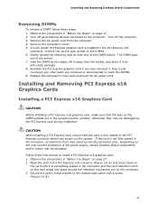
...7. Observe the precautions in the PCI Express x16 connector, remove the card to gain access to the computer. Turn off all peripheral devices connected to the DIMMs. 6. Hold the DIMM by the PCI Express card during installation. Depending on page 27. 2. Remove the computer's cover...an anti-static package. 8. Installing and Replacing Desktop Board Components Removing DIMMs To remove a DIMM, follow these instructions to the chassis back panel with a screw (Figure 19, B). 41 Replace the computer's cover and reconnect the AC power cord. CAUTION When installing a PCI Express...
...7. Observe the precautions in the PCI Express x16 connector, remove the card to gain access to the computer. Turn off all peripheral devices connected to the DIMMs. 6. Hold the DIMM by the PCI Express card during installation. Depending on page 27. 2. Remove the computer's cover...an anti-static package. 8. Installing and Replacing Desktop Board Components Removing DIMMs To remove a DIMM, follow these instructions to the chassis back panel with a screw (Figure 19, B). 41 Replace the computer's cover and reconnect the AC power cord. CAUTION When installing a PCI Express...

Product Guide
Page 42
Intel Desktop Board DH55TC Product Guide 4. Observe the precautions in the notch. Push the card ejector lever down using the tip of a pencil or similar tool (Figure 20, B) in "Before You Begin" on page 27. 2. This will release the card from a connector: 1. Connect a monitor to ...the graphics card according to remove it. 42 Pull the card straight up to the manufacturer's instructions. Figure 19. Installing a PCI Express x16 Graphics Card Removing a PCI Express x16 Graphics Card Follow these instructions to the chassis back panel. 4. Remove ...
Intel Desktop Board DH55TC Product Guide 4. Observe the precautions in the notch. Push the card ejector lever down using the tip of a pencil or similar tool (Figure 20, B) in "Before You Begin" on page 27. 2. This will release the card from a connector: 1. Connect a monitor to ...the graphics card according to remove it. 42 Pull the card straight up to the manufacturer's instructions. Figure 19. Installing a PCI Express x16 Graphics Card Removing a PCI Express x16 Graphics Card Follow these instructions to the chassis back panel. 4. Remove ...

Product Guide
Page 49
...usually white or striped. 49 Table 9 shows the pin assignments for the front panel header. Pins 1 and 3 of the front panel header. Reset Switch On/Off Switch 5 Ground 7 Reset switch 6 Power switch In 8 Ground Power Not Connected 9 Power Out 10 No pin In/Out Out Out In NOTE When... connecting individual wires from your chassis has a three-pin power LED cable, connect it to +5 V Out 3 Hard disk active LED Out 2 Front panel LED+ 4 Front panel LED- Installing and Replacing Desktop Board Components Pin Standard Signal Name ECP ...
...usually white or striped. 49 Table 9 shows the pin assignments for the front panel header. Pins 1 and 3 of the front panel header. Reset Switch On/Off Switch 5 Ground 7 Reset switch 6 Power switch In 8 Ground Power Not Connected 9 Power Out 10 No pin In/Out Out Out In NOTE When... connecting individual wires from your chassis has a three-pin power LED cable, connect it to +5 V Out 3 Hard disk active LED Out 2 Front panel LED+ 4 Front panel LED- Installing and Replacing Desktop Board Components Pin Standard Signal Name ECP ...

Product Guide
Page 50
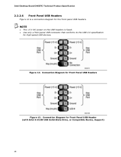
...a low-speed USB device is attached to the cable. Intel Desktop Board DH55TC Product Guide Front Panel USB 2.0 Headers Figure 23, G shows the location of the standard front panel USB 2.0 header and Table 12 shows its pin assignments and... signal names. Table 11. USB 2.0 Header Signal Names Pin Signal Name Pin 1 Power (+5 V) 2 3 D- 4 5 D+ 6 7 Ground 8 9 Key 10 Signal Name Power (+5 V) DD+ Ground No Connection...
...a low-speed USB device is attached to the cable. Intel Desktop Board DH55TC Product Guide Front Panel USB 2.0 Headers Figure 23, G shows the location of the standard front panel USB 2.0 header and Table 12 shows its pin assignments and... signal names. Table 11. USB 2.0 Header Signal Names Pin Signal Name Pin 1 Power (+5 V) 2 3 D- 4 5 D+ 6 7 Ground 8 9 Key 10 Signal Name Power (+5 V) DD+ Ground No Connection...
Product Guide
Page 51
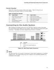
... Terminal Ready) 6 DSR (Data Set Ready) 8 CTS (Clear To Send) 10 Key (no pin) Connecting to power either headphones or amplified speakers only. Figure 24 shows the back panel audio connectors. Poor audio quality may occur if passive (non-amplified) speakers are shown in Figure 24. Table... Line out (front speaker/headphones) C Mic in the table. Back Panel Audio Connectors NOTE The back panel line out connector is designed to the Audio System After installing the Realtek audio driver from the Intel® Express Installer DVD-ROM, the multi-channel audio feature can be...
... Terminal Ready) 6 DSR (Data Set Ready) 8 CTS (Clear To Send) 10 Key (no pin) Connecting to power either headphones or amplified speakers only. Figure 24 shows the back panel audio connectors. Poor audio quality may occur if passive (non-amplified) speakers are shown in Figure 24. Table... Line out (front speaker/headphones) C Mic in the table. Back Panel Audio Connectors NOTE The back panel line out connector is designed to the Audio System After installing the Realtek audio driver from the Intel® Express Installer DVD-ROM, the multi-channel audio feature can be...
DH55TC Technical Product Specification
Page 7
...48 13. Components Shown in Figure 10 40 10. S/PDIF Header 42 13. Internal Mono Speaker Header 42 14. Connection Diagram for Front Panel USB Header (with Intel Z-U130 USB Solid-State Drive, or Compatible Device, Support 43 18. Localized High Temperature Zones 55 Tables 1. System ...Memory Map 37 9. SATA Connectors 43 19. Back Panel Connectors 38 10. LAN Connector LED States 24 5. Processor (4-Pin) Fan Header 43 20. Block Diagram 13 3. Connection Diagram for Intel HD Audio 42 15. Contents Figures 1. Power States and Targeted System Power 28...
...48 13. Components Shown in Figure 10 40 10. S/PDIF Header 42 13. Internal Mono Speaker Header 42 14. Connection Diagram for Front Panel USB Header (with Intel Z-U130 USB Solid-State Drive, or Compatible Device, Support 43 18. Localized High Temperature Zones 55 Tables 1. System ...Memory Map 37 9. SATA Connectors 43 19. Back Panel Connectors 38 10. LAN Connector LED States 24 5. Processor (4-Pin) Fan Header 43 20. Block Diagram 13 3. Connection Diagram for Intel HD Audio 42 15. Contents Figures 1. Power States and Targeted System Power 28...
DH55TC Technical Product Specification
Page 21
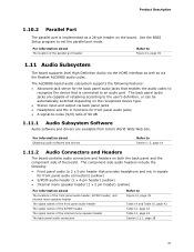
...the parallel port header Refer to Figure 10, page 39 1.11 Audio Subsystem The board supports Intel High Definition Audio via the HDMI interface as well as a 26-pin header on the board. The back panel audio jacks are capable of retasking according to the user's definition, or can be automatically switched... side of the internal mono speaker header The back panel audio connectors Refer to Figure 10, page 39 Table 14 and Table 15, page 42 Table 12, page 42 Table 13, page 42 Section 2.2.1, page 38 21 Product Description 1.10.2 Parallel Port The parallel port is connected to an audio port.
...the parallel port header Refer to Figure 10, page 39 1.11 Audio Subsystem The board supports Intel High Definition Audio via the HDMI interface as well as a 26-pin header on the board. The back panel audio jacks are capable of retasking according to the user's definition, or can be automatically switched... side of the internal mono speaker header The back panel audio connectors Refer to Figure 10, page 39 Table 14 and Table 15, page 42 Table 12, page 42 Table 13, page 42 Section 2.2.1, page 38 21 Product Description 1.10.2 Parallel Port The parallel port is connected to an audio port.

DH55TC Technical Product Specification
Page 22
... load of 8 Ohms at 1 W (rms) or 4 Ohms at 1.5 W (rms). 22 Intel Desktop Board DH55TC Technical Product Specification 1.11.2.1 Analog Audio Connectivity The available configurable back panel audio connectors are configurable through back panel speakers and front panel headset, respectively). 1.11.2.2 SPDIF Connectivity The SPDIF header allows connectivity to coaxial or optical dongles for digital audio output. 1.11.2.3 Internal...
... load of 8 Ohms at 1 W (rms) or 4 Ohms at 1.5 W (rms). 22 Intel Desktop Board DH55TC Technical Product Specification 1.11.2.1 Analog Audio Connectivity The available configurable back panel audio connectors are configurable through back panel speakers and front panel headset, respectively). 1.11.2.2 SPDIF Connectivity The SPDIF header allows connectivity to coaxial or optical dongles for digital audio output. 1.11.2.3 Internal...
DH55TC Technical Product Specification
Page 37
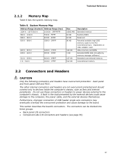
... BIOS Extended BIOS data (movable by the external devices could cause damage to the PCI Conventional bus). Furthermore, improper connection of USB header single wire connectors may eventually overload the overcurrent protection and cause damage to devices inside the computer's ...these groups: • Back panel I/O connectors • Component-side I/O connectors and headers (see page 39) 37 DFFFF 640 K - 800 K 639 K - 640 K 512 K - 639 K 0 K - 512 K A0000 - The other internal connectors and headers are not overcurrent protected and should connect only to the board. C7FFF ...
... BIOS Extended BIOS data (movable by the external devices could cause damage to the PCI Conventional bus). Furthermore, improper connection of USB header single wire connectors may eventually overload the overcurrent protection and cause damage to devices inside the computer's ...these groups: • Back panel I/O connectors • Component-side I/O connectors and headers (see page 39) 37 DFFFF 640 K - 800 K 639 K - 640 K 512 K - 639 K 0 K - 512 K A0000 - The other internal connectors and headers are not overcurrent protected and should connect only to the board. C7FFF ...
DH55TC Technical Product Specification
Page 38
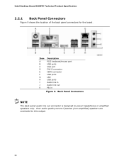
Poor audio quality occurs if passive (non-amplified) speakers are connected to power headphones or amplified speakers only. Intel Desktop Board DH55TC Technical Product Specification 2.2.1 Back Panel Connectors Figure 9 shows the location of the back panel connectors for the board. Back Panel Connectors NOTE The back panel audio line out connector is designed to this output. 38 Item A B C D E F G H I J K Description PS/2 keyboard/mouse port USB ports VGA port DVI-D connector HDMI connector USB ports LAN USB ports Audio line in Audio line out Mic in Figure 9.
Poor audio quality occurs if passive (non-amplified) speakers are connected to power headphones or amplified speakers only. Intel Desktop Board DH55TC Technical Product Specification 2.2.1 Back Panel Connectors Figure 9 shows the location of the back panel connectors for the board. Back Panel Connectors NOTE The back panel audio line out connector is designed to this output. 38 Item A B C D E F G H I J K Description PS/2 keyboard/mouse port USB ports VGA port DVI-D connector HDMI connector USB ports LAN USB ports Audio line in Audio line out Mic in Figure 9.

DH55TC Technical Product Specification
Page 46
... an onboard SATA connector, or the use of the front panel header. Connection Diagram for the front panel header. Intel Desktop Board DH55TC Technical Product Specification 2.2.2.4 Front Panel Header This section describes the functions of an Intel Z-U130 Solid-State Drive (or compatible device). 46 Front Panel Header Pin Signal In/ Out Description Hard Drive Activity LED 1 HD_PWR...
... an onboard SATA connector, or the use of the front panel header. Connection Diagram for the front panel header. Intel Desktop Board DH55TC Technical Product Specification 2.2.2.4 Front Panel Header This section describes the functions of an Intel Z-U130 Solid-State Drive (or compatible device). 46 Front Panel Header Pin Signal In/ Out Description Hard Drive Activity LED 1 HD_PWR...
DH55TC Technical Product Specification
Page 47
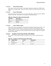
...2.2.2.4.4 Power Switch Header Pins 6 and 8 can be connected to a one- or two-color LED. Table 24 shows the default states for this header duplicate the signals on pins 2 and 4 of the front panel header. Auxiliary Front Panel Power LED Header Pin Signal Name In/Out Description 1 ...FP_LED+ Out 2 Not connected 3 FP_LED− Out FP_LED+ FP_LED− 47 Table 24. More options are available ...
...2.2.2.4.4 Power Switch Header Pins 6 and 8 can be connected to a one- or two-color LED. Table 24 shows the default states for this header duplicate the signals on pins 2 and 4 of the front panel header. Auxiliary Front Panel Power LED Header Pin Signal Name In/Out Description 1 ...FP_LED+ Out 2 Not connected 3 FP_LED− Out FP_LED+ FP_LED− 47 Table 24. More options are available ...
DH55TC Technical Product Specification
Page 48
Connection Diagram for Front Panel USB Header (with Intel Z-U130 USB Solid-State Drive, or Compatible Device, Support) 48 Connection Diagram for Front Panel USB Headers Figure 13. NOTE • The +5 V DC power on the USB headers is a connection diagram for high-speed USB devices. Intel Desktop Board DH55TC Technical Product Specification 2.2.2.6 Front Panel USB Headers Figure 12 is fused. • Use only a front panel USB connector that conforms to the USB 2.0 specification for the front panel USB headers. Figure 12.
Connection Diagram for Front Panel USB Header (with Intel Z-U130 USB Solid-State Drive, or Compatible Device, Support) 48 Connection Diagram for Front Panel USB Headers Figure 13. NOTE • The +5 V DC power on the USB headers is a connection diagram for high-speed USB devices. Intel Desktop Board DH55TC Technical Product Specification 2.2.2.6 Front Panel USB Headers Figure 12 is fused. • Use only a front panel USB connector that conforms to the USB 2.0 specification for the front panel USB headers. Figure 12.
DH55TC Specification Update
Page 7
.... • Three Conventional PCI (rev 2.3 compliant) connectors. 2.2.2.6 Front Panel USB Headers Figure 12 is fused. • Use only a front panel USB connector that has any connection to Pin 10, may cause the HDD LED to the Intel® Desktop Board DH55TC Technical Product Specification (Order Number E81940). 1. Connecting any device to this header, that conforms to...
.... • Three Conventional PCI (rev 2.3 compliant) connectors. 2.2.2.6 Front Panel USB Headers Figure 12 is fused. • Use only a front panel USB connector that has any connection to Pin 10, may cause the HDD LED to the Intel® Desktop Board DH55TC Technical Product Specification (Order Number E81940). 1. Connecting any device to this header, that conforms to...


