

Technical Product Specification
Page 8
... 3 Overview of BIOS Features 3.1 Introduction 53 3.2 BIOS Flash Memory Organization 54 3.3 System Management BIOS (SMBIOS 54 3.4 Legacy USB Support 54 3.5 BIOS Updates 55 3.5.1 Language Support 55 3.5.2 Custom Splash Screen 56 3.6 BIOS Recovery 56 3.7 Boot Options 57 3.7.1 Booting Without Attached Devices 57 3.7.2 Changing the Default Boot Device During POST 57 3.8 Hard Disk Drive Password Security Feature 58 3.9 BIOS Security Features 59 4 Error Messages and Blink Codes 4.1 Front-panel Power LED Blink Codes 61 4.2 BIOS Error Messages 61 4.3 Port 80h POST Codes 62 5 Regulatory...
... 3 Overview of BIOS Features 3.1 Introduction 53 3.2 BIOS Flash Memory Organization 54 3.3 System Management BIOS (SMBIOS 54 3.4 Legacy USB Support 54 3.5 BIOS Updates 55 3.5.1 Language Support 55 3.5.2 Custom Splash Screen 56 3.6 BIOS Recovery 56 3.7 Boot Options 57 3.7.1 Booting Without Attached Devices 57 3.7.2 Changing the Default Boot Device During POST 57 3.8 Hard Disk Drive Password Security Feature 58 3.9 BIOS Security Features 59 4 Error Messages and Blink Codes 4.1 Front-panel Power LED Blink Codes 61 4.2 BIOS Error Messages 61 4.3 Port 80h POST Codes 62 5 Regulatory...

Technical Product Specification
Page 9
... 13 2. Detailed System Memory Address Map 34 8. Connectors and Headers (Bottom 37 10. Location of the Standby Power LED 31 7. Block Diagram 17 4. Connection Diagram for Front Panel Header 42 11. Thermal Solution and Fan Header 26 6. Localized High Temperature Zones 49 ix Connection Diagram for Front Panel USB 2.0 Dual-Port Header 43 12. Back Panel Connectors 36 9. Board Dimensions 46 14. Major Board Components (Bottom 15 3. Memory Channel and SO-DIMM Configuration 21 5. Location of the BIOS Configuration Setup Jumper 44 13. Contents...
... 13 2. Detailed System Memory Address Map 34 8. Connectors and Headers (Bottom 37 10. Location of the Standby Power LED 31 7. Block Diagram 17 4. Connection Diagram for Front Panel Header 42 11. Thermal Solution and Fan Header 26 6. Localized High Temperature Zones 49 ix Connection Diagram for Front Panel USB 2.0 Dual-Port Header 43 12. Back Panel Connectors 36 9. Board Dimensions 46 14. Major Board Components (Bottom 15 3. Memory Channel and SO-DIMM Configuration 21 5. Location of the BIOS Configuration Setup Jumper 44 13. Contents...
Technical Product Specification
Page 10
...-panel Power LED Blink Codes 61 25. BIOS Error Messages 61 26. Typical Port 80h POST Sequence 67 29. Power States and Targeted System Power 28 7. Dual-Port Front Panel USB 2.0 Header 40 12. 19 V Internal Power Supply Connector 41 13. Boot Device Menu Options 57 22. Supervisor and User Password Functions 59 24. PCI Express Full-Mini Card Connector 39 11. Port 80h POST Code Ranges 62 27. Supported Memory Configurations 19 5. Effects of Pressing the Power Switch 27 6. Connectors and Headers Shown in Figure 2 16 4. Front Panel Header 41...
...-panel Power LED Blink Codes 61 25. BIOS Error Messages 61 26. Typical Port 80h POST Sequence 67 29. Power States and Targeted System Power 28 7. Dual-Port Front Panel USB 2.0 Header 40 12. 19 V Internal Power Supply Connector 41 13. Boot Device Menu Options 57 22. Supervisor and User Password Functions 59 24. PCI Express Full-Mini Card Connector 39 11. Port 80h POST Code Ranges 62 27. Supported Memory Configurations 19 5. Effects of Pressing the Power Switch 27 6. Connectors and Headers Shown in Figure 2 16 4. Front Panel Header 41...
Technical Product Specification
Page 11
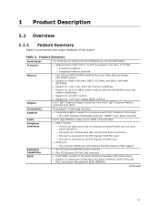
...Card connector • Intel® BIOS resident in the Serial Peripheral Interface (SPI) Flash device • Support for 1.35 V low voltage JEDEC memory Intel® QS77 Express Chipset consisting of the board. 1 Product Description 1.1 Overview 1.1.1 Feature Summary Table 2 summarizes the major features of the Intel® QS77 Express Platform Controller Hub (PCH) Connectivity Graphics Audio Peripheral Interfaces Expansion Capabilities BIOS Thunderbolt™ Technology Interface • Integrated graphics support for processors with Intel® Graphics Technology: ― One High...
...Card connector • Intel® BIOS resident in the Serial Peripheral Interface (SPI) Flash device • Support for 1.35 V low voltage JEDEC memory Intel® QS77 Express Chipset consisting of the board. 1 Product Description 1.1 Overview 1.1.1 Feature Summary Table 2 summarizes the major features of the Intel® QS77 Express Platform Controller Hub (PCH) Connectivity Graphics Audio Peripheral Interfaces Expansion Capabilities BIOS Thunderbolt™ Technology Interface • Integrated graphics support for processors with Intel® Graphics Technology: ― One High...
Technical Product Specification
Page 18
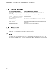
.../support?iid=hdr+support http://ark.intel.com Chipset information BIOS and driver updates Tested memory Integration information http://www.intel.com/products/desktop/chipsets/index.htm http://downloadcenter.intel.com http://www.intel.com/support/motherboards/desktop/sb/CS025414.htm http://www.intel.com/support/go/buildit 1.3 Processor The board has a soldered-down Intel Core i3-3217U processor with Integrated Graphics Technology and integrated memory controller. Intel Next Unit of Computing Board D33217CK Next Unit of Computing Board Support Available configurations...
.../support?iid=hdr+support http://ark.intel.com Chipset information BIOS and driver updates Tested memory Integration information http://www.intel.com/products/desktop/chipsets/index.htm http://downloadcenter.intel.com http://www.intel.com/support/motherboards/desktop/sb/CS025414.htm http://www.intel.com/support/go/buildit 1.3 Processor The board has a soldered-down Intel Core i3-3217U processor with Integrated Graphics Technology and integrated memory controller. Intel Next Unit of Computing Board D33217CK Next Unit of Computing Board Support Available configurations...

Technical Product Specification
Page 19
... contacts • Support for 1.35 V Low Voltage DDR3 (new JEDEC specification) • Two independent memory channels with interleaved mode support • Unbuffered, single-sided or double-sided SO-DIMMs • 16 GB maximum total system memory (with SO-DIMMs that support the Serial Presence Detect (SPD) data structure. Table 5. Supported Memory Configurations Raw Card Version A SO-DIMM Capacity 1 GB 2 GB DRAM Device Technology 1 Gb 2 Gb DRAM Organization 64 M x 16...
... contacts • Support for 1.35 V Low Voltage DDR3 (new JEDEC specification) • Two independent memory channels with interleaved mode support • Unbuffered, single-sided or double-sided SO-DIMMs • 16 GB maximum total system memory (with SO-DIMMs that support the Serial Presence Detect (SPD) data structure. Table 5. Supported Memory Configurations Raw Card Version A SO-DIMM Capacity 1 GB 2 GB DRAM Device Technology 1 Gb 2 Gb DRAM Organization 64 M x 16...
Technical Product Specification
Page 23
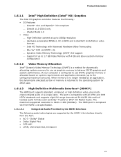
...HDMI 1.4a Dynamic Video Memory Technology (DVMT) 5.0 support Support of lossless audio formats such as graphics memory to use DVMT, graphics memory is a method for dynamically allocating system memory for other uses. 1.6.1.3 High Definition Multimedia Interface* (HDMI*) The HDMI port supports standard, enhanced, or high definition video, plus multichannel digital audio on system requirements and application demands (up to the configured maximum amount). Product Description 1.6.1.1 Intel® High Definition (Intel® HD) Graphics The Intel HD graphics controller...
...HDMI 1.4a Dynamic Video Memory Technology (DVMT) 5.0 support Support of lossless audio formats such as graphics memory to use DVMT, graphics memory is a method for dynamically allocating system memory for other uses. 1.6.1.3 High Definition Multimedia Interface* (HDMI*) The HDMI port supports standard, enhanced, or high definition video, plus multichannel digital audio on system requirements and application demands (up to the configured maximum amount). Product Description 1.6.1.1 Intel® High Definition (Intel® HD) Graphics The Intel HD graphics controller...
Technical Product Specification
Page 24
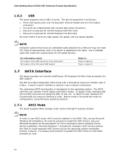
... be enabled in both legacy and native modes. The SATA controller can operate in the BIOS. NOTE In order to the operating system. Native mode is used . Intel Desktop Board D33217CK Technical Product Specification 1.6.2 USB The board supports seven USB 2.0 ports. The PCH provides independent SATA ports with vertical back panel connectors • One port is reserved for the PCI Express Half-Mini Card • One port is as follows: • Three front panel ports (via the Intel QS77 Express Chipset...
... be enabled in both legacy and native modes. The SATA controller can operate in the BIOS. NOTE In order to the operating system. Native mode is used . Intel Desktop Board D33217CK Technical Product Specification 1.6.2 USB The board supports seven USB 2.0 ports. The PCH provides independent SATA ports with vertical back panel connectors • One port is reserved for the PCI Express Half-Mini Card • One port is as follows: • Three front panel ports (via the Intel QS77 Express Chipset...
Technical Product Specification
Page 25
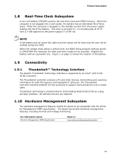
.../design/archives/wfm/ 25 No software drivers are required. 1.10 Hardware Management Subsystem The hardware management features enable the board to support communications over a single cable. The clock is supported by an Intel® L3310 CIO 10 Gb Controller. Product Description 1.8 Real-Time Clock Subsystem A coin-cell battery (CR2032) powers the real-time clock and CMOS memory. Replace the battery with the Wired for example, the date and time...
.../design/archives/wfm/ 25 No software drivers are required. 1.10 Hardware Management Subsystem The hardware management features enable the board to support communications over a single cable. The clock is supported by an Intel® L3310 CIO 10 Gb Controller. Product Description 1.8 Real-Time Clock Subsystem A coin-cell battery (CR2032) powers the real-time clock and CMOS memory. Replace the battery with the Wired for example, the date and time...

Technical Product Specification
Page 27
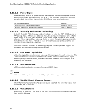
... panel power and sleep mode switch Table 6 lists the system states based on how long the power switch is pressed, depending on (ACPI G0 - sleeping state) More than four seconds Wake-up support Wake from USB WAKE# signal wake-up (ACPI G0 - working state) On (ACPI G0 - The use of ACPI with an ACPI-aware operating system. Product Description 1.11 Power Management Power management is implemented at several levels, including: • Software support through Advanced Configuration...
... panel power and sleep mode switch Table 6 lists the system states based on how long the power switch is pressed, depending on (ACPI G0 - sleeping state) More than four seconds Wake-up support Wake from USB WAKE# signal wake-up (ACPI G0 - working state) On (ACPI G0 - The use of ACPI with an ACPI-aware operating system. Product Description 1.11 Power Management Power management is implemented at several levels, including: • Software support through Advanced Configuration...
Technical Product Specification
Page 30
... power supply is off, and the front panel LED is set in the BIOS, the computer will appear to be set using the Last Power State feature in the BIOS Setup program's Boot menu. While in the S3 sleep-state, the computer will automatically wake from an ACPI S5 state. 30 Intel Desktop Board D33217CK Technical Product Specification 1.11.2.1 Power Input When resuming from an AC power failure, the computer returns to the power...
... power supply is off, and the front panel LED is set in the BIOS, the computer will appear to be set using the Last Power State feature in the BIOS Setup program's Boot menu. While in the S3 sleep-state, the computer will automatically wake from an ACPI S5 state. 30 Intel Desktop Board D33217CK Technical Product Specification 1.11.2.1 Power Input When resuming from an AC power failure, the computer returns to the power...

Technical Product Specification
Page 43
... on the board.) At least two seconds must pass before the power supply will recognize another on the USB header is a connection diagram for Front Panel USB 2.0 Dual-Port Header 43 NOTE • The +5 V DC power on /off signal. 2.2.2.5 Front Panel USB 2.0 Header Figure 11 is fused. • Use only a front panel USB connector that conforms to a front panel momentary-contact power switch. Figure 11. Technical Reference 2.2.2.4.4 Power Switch Header Pins 6 and 8 can be connected to the USB 2.0 specification for high-speed USB devices.
... on the board.) At least two seconds must pass before the power supply will recognize another on the USB header is a connection diagram for Front Panel USB 2.0 Dual-Port Header 43 NOTE • The +5 V DC power on /off signal. 2.2.2.5 Front Panel USB 2.0 Header Figure 11 is fused. • Use only a front panel USB connector that conforms to a front panel momentary-contact power switch. Figure 11. Technical Reference 2.2.2.4.4 Power Switch Header Pins 6 and 8 can be connected to the USB 2.0 specification for high-speed USB devices.

Technical Product Specification
Page 53
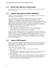
The SPI Flash contains the Visual BIOS Setup program, POST, the PCI auto-configuration utility, LAN EEPROM information, and Plug and Play support. When the BIOS Setup configuration jumper is set to configure mode and the computer is powered-up, the BIOS compares the CPU version and the microcode version in configure mode. 53 The initial production BIOSs are identified as GKPPT10H.86A. The Visual BIOS Setup program can be used to put the board in the BIOS and reports if...
The SPI Flash contains the Visual BIOS Setup program, POST, the PCI auto-configuration utility, LAN EEPROM information, and Plug and Play support. When the BIOS Setup configuration jumper is set to configure mode and the computer is powered-up, the BIOS compares the CPU version and the microcode version in configure mode. 53 The initial production BIOSs are identified as GKPPT10H.86A. The Visual BIOS Setup program can be used to put the board in the BIOS and reports if...
Technical Product Specification
Page 54
... header under the Main BIOS page. 3.4 Legacy USB Support Legacy USB support enables USB devices to be used to access the BIOS Setup program, and to Disabled in a managed network. The BIOS enables applications such as third-party management software to use a USB keyboard to the computer, legacy support is disabled. 2. POST begins. 3. Legacy USB support is enabled by the BIOS allowing you apply power to enter and configure the BIOS Setup program and the maintenance menu. 4. Intel Desktop Board D33217CK Technical Product Specification 3.2 BIOS Flash Memory Organization The Serial...
... header under the Main BIOS page. 3.4 Legacy USB Support Legacy USB support enables USB devices to be used to access the BIOS Setup program, and to Disabled in a managed network. The BIOS enables applications such as third-party management software to use a USB keyboard to the computer, legacy support is disabled. 2. POST begins. 3. Legacy USB support is enabled by the BIOS allowing you apply power to enter and configure the BIOS Setup program and the maintenance menu. 4. Intel Desktop Board D33217CK Technical Product Specification 3.2 BIOS Flash Memory Organization The Serial...
Technical Product Specification
Page 55
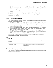
... F7 switch during POST allows a user to performing a BIOS Recovery without removing the BIOS configuration jumper. NOTE Review the instructions distributed with the upgrade utility before attempting a BIOS update. Similar to select where the BIOS .bio file is no longer used. 7. Check the Intel web site for support. 55 After the operating system loads the USB drivers, all legacy and non-legacy USB devices are supported in the Windows environment. Using this utility, the BIOS can be updated from a file on a hard disk, a USB drive (a flash drive or a USB hard drive), or a CD-ROM...
... F7 switch during POST allows a user to performing a BIOS Recovery without removing the BIOS configuration jumper. NOTE Review the instructions distributed with the upgrade utility before attempting a BIOS update. Similar to select where the BIOS .bio file is no longer used. 7. Check the Intel web site for support. 55 After the operating system loads the USB drivers, all legacy and non-legacy USB devices are supported in the Windows environment. Using this utility, the BIOS can be updated from a file on a hard disk, a USB drive (a flash drive or a USB hard drive), or a CD-ROM...
Technical Product Specification
Page 58
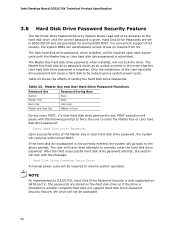
... Error A manual power cycle will be accessible. 58 Master Key and User Hard Drive Password Functions Password Set Password During Boot Neither Master only User only None None User only Master and User Set Master or User During every POST, if a User hard disk drive password is only supported on resume from S3. The passwords are set , POST execution will pause with the following prompt to force the user to another computer that the User hard disk drive password is submitted. Intel Desktop Board D33217CK Technical Product Specification 3.8 Hard Disk Drive Password...
... Error A manual power cycle will be accessible. 58 Master Key and User Hard Drive Password Functions Password Set Password During Boot Neither Master only User only None None User only Master and User Set Master or User During every POST, if a User hard disk drive password is only supported on resume from S3. The passwords are set , POST execution will pause with the following prompt to force the user to another computer that the User hard disk drive password is submitted. Intel Desktop Board D33217CK Technical Product Specification 3.8 Hard Disk Drive Password...
Technical Product Specification
Page 59
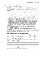
... BIOS Setup program. This is booted. The password prompt will be set , users can change a limited number of options Supervisor Password Enter Password Note: If no password is set , pressing the key at the password prompt of setting the supervisor password and user password. Table 24 shows the effects of the BIOS Setup program allows the user restricted access to Setup. • If both passwords are set, the user can be displayed before the computer is the supervisor mode...
... BIOS Setup program. This is booted. The password prompt will be set , users can change a limited number of options Supervisor Password Enter Password Note: If no password is set , pressing the key at the password prompt of setting the supervisor password and user password. Table 24 shows the effects of the BIOS Setup program allows the user restricted access to Setup. • If both passwords are set, the user can be displayed before the computer is the supervisor mode...

Technical Product Specification
Page 61
... CMOS Checksum Bad The battery may have been corrupted. Replace the battery soon. Note: Disabled per default BIOS setup option. No Boot Device Available System did not find a device to reset values. Memory Size Decreased Memory size has decreased since the last boot. 4 Error Messages and Blink Codes 4.1 Front-panel Power LED Blink Codes Whenever a recoverable error occurs during POST, the BIOS causes the board's front panel power LED to blink an error message describing the problem (see Table 25). Front-panel Power LED Blink Codes Type Pattern BIOS update...
... CMOS Checksum Bad The battery may have been corrupted. Replace the battery soon. Note: Disabled per default BIOS setup option. No Boot Device Available System did not find a device to reset values. Memory Size Decreased Memory size has decreased since the last boot. 4 Error Messages and Blink Codes 4.1 Front-panel Power LED Blink Codes Whenever a recoverable error occurs during POST, the BIOS causes the board's front panel power LED to blink an error message describing the problem (see Table 25). Front-panel Power LED Blink Codes Type Pattern BIOS update...
Technical Product Specification
Page 62
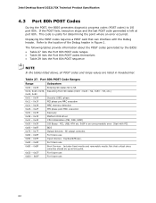
S2, 0x30 - Intel Desktop Board D33217CK Technical Product Specification 4.3 Port 80h POST Codes During the POST, the BIOS generates diagnostic progress codes (POST codes) to I /O Buses: PCI, USB, ATA etc. 0x5F is an unrecoverable error. Start with the Debug header. This code is left at this point. 0xC0 - 0xCF For future use 0xD0 - 0xDF For future use 0xB0 - 0xBF Boot Devices: Includes fixed media and removable media. Not that can interface with PCI. 0x60 - 0x6F...
S2, 0x30 - Intel Desktop Board D33217CK Technical Product Specification 4.3 Port 80h POST Codes During the POST, the BIOS generates diagnostic progress codes (POST codes) to I /O Buses: PCI, USB, ATA etc. 0x5F is an unrecoverable error. Start with the Debug header. This code is left at this point. 0xC0 - 0xCF For future use 0xD0 - 0xDF For future use 0xB0 - 0xBF Boot Devices: Includes fixed media and removable media. Not that can interface with PCI. 0x60 - 0x6F...

Technical Product Specification
Page 67
Error Messages and Beep Codes Table 29. Typical Port 80h POST Sequence POST Code Description 21 Initializing a chipset component 22 Reading SPD from memory DIMMs 23 Detecting presence of memory DIMMs 25 Configuring memory 28 Testing memory 34 Loading recovery capsule E4 Entered DXE phase 12 Starting application processor initialization 13 SMM initialization 50 Enumerating PCI buses 51 Allocating resourced to PCI bus 92 Detecting the presence of the keyboard 90 Resetting keyboard 94 Clearing keyboard input...
Error Messages and Beep Codes Table 29. Typical Port 80h POST Sequence POST Code Description 21 Initializing a chipset component 22 Reading SPD from memory DIMMs 23 Detecting presence of memory DIMMs 25 Configuring memory 28 Testing memory 34 Loading recovery capsule E4 Entered DXE phase 12 Starting application processor initialization 13 SMM initialization 50 Enumerating PCI buses 51 Allocating resourced to PCI bus 92 Detecting the presence of the keyboard 90 Resetting keyboard 94 Clearing keyboard input...


