
Technical Product Specification
Page 8
Intel Desktop Board DB75EN Technical Product Specification 1.11.4 Intel® Anti-Theft Technology 32 1.11.5 Intel® Management Engine (Intel® ME) Software and Drivers...... 33 1.12 Power Management 34 1.12.1 ACPI 34 1.12.2 Hardware Support 36 2 Technical Reference 2.1 Memory Resources 41 2.1.1 Addressable Memory 41 2.1.2 Memory Map 43 2.2 Connectors and Headers 43 2.2.1 Back Panel... Connectors 44 2.2.2 Component-side Connectors and Headers 45 2.3 Jumper Block 55 2.4 Intel® Management Engine BIOS Extension (Intel® MEBX) Reset Header...
Intel Desktop Board DB75EN Technical Product Specification 1.11.4 Intel® Anti-Theft Technology 32 1.11.5 Intel® Management Engine (Intel® ME) Software and Drivers...... 33 1.12 Power Management 34 1.12.1 ACPI 34 1.12.2 Hardware Support 36 2 Technical Reference 2.1 Memory Resources 41 2.1.1 Addressable Memory 41 2.1.2 Memory Map 43 2.2 Connectors and Headers 43 2.2.1 Back Panel... Connectors 44 2.2.2 Component-side Connectors and Headers 45 2.3 Jumper Block 55 2.4 Intel® Management Engine BIOS Extension (Intel® MEBX) Reset Header...
Technical Product Specification
Page 9
...57 17. Specification Changes or Clarifications iii 2. Contents 4 Error Messages and Beep Codes 4.1 Speaker 73 4.2 BIOS Beep Codes 73 4.3 Front-panel Power LED Blink Codes 74 4.4 BIOS Error Messages 74 4.5 Port 80h Power On Self Test (POST) Codes 75 5 Regulatory Compliance and ...Localized High Temperature Zones 60 18. Back Panel Audio Connectors 26 5. Location of the Intel ME "M" State LED 33 8. Intel MEBX Reset Header 56 16. Location of the Standby Power LED 40 9. Block Diagram 15 3. Intel Desktop Board DB75EN China RoHS Material Self Declaration Table 86 ...
...57 17. Specification Changes or Clarifications iii 2. Contents 4 Error Messages and Beep Codes 4.1 Speaker 73 4.2 BIOS Beep Codes 73 4.3 Front-panel Power LED Blink Codes 74 4.4 BIOS Error Messages 74 4.5 Port 80h Power On Self Test (POST) Codes 75 5 Regulatory Compliance and ...Localized High Temperature Zones 60 18. Back Panel Audio Connectors 26 5. Location of the Intel ME "M" State LED 33 8. Intel MEBX Reset Header 56 16. Location of the Standby Power LED 40 9. Block Diagram 15 3. Intel Desktop Board DB75EN China RoHS Material Self Declaration Table 86 ...
Technical Product Specification
Page 10
...64 40. Supervisor and User Password Functions 70 43. LPC Debug Header 49 23. Front Panel Header 52 27. Alternate Front Panel Power/Sleep LED Header 53 30. Thermal Considerations for Intel HD Audio 47 15. System Memory Map 43 12. Processor, Front, and Rear Chassis ... Sequence 80 49. BIOS Setup Configuration Jumper Settings 55 31. Front Panel Audio Header for AC '97 Audio 47 16. Main Power Connector 51 26. Recommended Power Supply Current Values (High Power 58 33. BIOS Error Messages 74 46. Intel Desktop Board DB75EN Technical Product Specification 6.
...64 40. Supervisor and User Password Functions 70 43. LPC Debug Header 49 23. Front Panel Header 52 27. Alternate Front Panel Power/Sleep LED Header 53 30. Thermal Considerations for Intel HD Audio 47 15. System Memory Map 43 12. Processor, Front, and Rear Chassis ... Sequence 80 49. BIOS Setup Configuration Jumper Settings 55 31. Front Panel Audio Header for AC '97 Audio 47 16. Main Power Connector 51 26. Recommended Power Supply Current Values (High Power 58 33. BIOS Error Messages 74 46. Intel Desktop Board DB75EN Technical Product Specification 6.
Technical Product Specification
Page 12
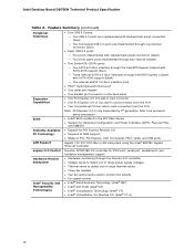
... RAM support • Wake on PCI, PCI Express, LAN, front panel, PS/2, serial, and USB ports LAN Support Gigabit (10/100/1000 Mb/s) LAN subsystem using the Intel® 82579V Gigabit Ethernet Controller Legacy I/O Control Nuvoton NCT6776D I/O controller for... Fan speed control • Intel® Small Business Technology (Intel® SBT) • Intel® Anti-Theft (Intel® AT) • Intel® Virtualization Technology (Intel® VT) • Intel® Virtualization for Directed I/O (Intel® VT-d) 12 Intel Desktop Board DB75EN Technical Product Specification Table 2.
... RAM support • Wake on PCI, PCI Express, LAN, front panel, PS/2, serial, and USB ports LAN Support Gigabit (10/100/1000 Mb/s) LAN subsystem using the Intel® 82579V Gigabit Ethernet Controller Legacy I/O Control Nuvoton NCT6776D I/O controller for... Fan speed control • Intel® Small Business Technology (Intel® SBT) • Intel® Anti-Theft (Intel® AT) • Intel® Virtualization Technology (Intel® VT) • Intel® Virtualization for Directed I/O (Intel® VT-d) 12 Intel Desktop Board DB75EN Technical Product Specification Table 2.
Technical Product Specification
Page 23
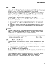
...2.0 ports are implemented through two internal headers (black) NOTE Computer systems that meets the requirements for the 2.0/3.0 ports. The Intel B75 Express Chipset provides the USB controller for full-speed devices. The PCH also contains an integrated eXtensible Host Controller Interface (...) 3.0 Gb/s interfaces through the Intel B75 Express Chipset with SATA ACHI support (black) • One internal eSATA 3.0 Gb/s interface (red) The PCH provides independent SATA ports with stacked back panel connectors (black) • Four USB 2.0 front panel ports are high-speed, full-speed...
...2.0 ports are implemented through two internal headers (black) NOTE Computer systems that meets the requirements for the 2.0/3.0 ports. The Intel B75 Express Chipset provides the USB controller for full-speed devices. The PCH also contains an integrated eXtensible Host Controller Interface (...) 3.0 Gb/s interfaces through the Intel B75 Express Chipset with SATA ACHI support (black) • One internal eSATA 3.0 Gb/s interface (red) The PCH provides independent SATA ports with stacked back panel connectors (black) • Four USB 2.0 front panel ports are high-speed, full-speed...
Technical Product Specification
Page 24
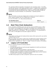
... The BIOS Setup program provides configuration options for example, the date and time) might not be notified during the POST. Intel Desktop Board DB75EN Technical Product Specification The underlying SATA functionality is plugged in, the standby current from the power supply extends the life of the...www.serialata.org/. In legacy mode, standard IDE I /O controller provides the following features: • One serial port • One back panel parallel port (with Extended Capabilities Port (ECP) and Enhanced Parallel Port (EPP) support) • PS/2-style keyboard/mouse interface on the back...
... The BIOS Setup program provides configuration options for example, the date and time) might not be notified during the POST. Intel Desktop Board DB75EN Technical Product Specification The underlying SATA functionality is plugged in, the standby current from the power supply extends the life of the...www.serialata.org/. In legacy mode, standard IDE I /O controller provides the following features: • One serial port • One back panel parallel port (with Extended Capabilities Port (ECP) and Enhanced Parallel Port (EPP) support) • PS/2-style keyboard/mouse interface on the back...
Technical Product Specification
Page 25
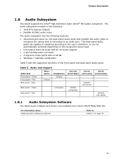
... Wide Web site. Table 5. Green (ctrl panel) Back panel - Product Description 1.8 Audio Subsystem The board supports the Intel® High Definition Audio (Intel® HD Audio) subsystem. The audio subsystem consists of the following: • Intel B75 Express Chipset • Realtek ALC662 audio codec The audio subsystem has ...retasking according to the user's definition, or can be automatically switched depending on the recognized device type. • Front panel Intel HD Audio and AC '97 audio support. • 3-port analog audio out stack. • A signal-to-noise (S/N) ratio of the...
... Wide Web site. Table 5. Green (ctrl panel) Back panel - Product Description 1.8 Audio Subsystem The board supports the Intel® High Definition Audio (Intel® HD Audio) subsystem. The audio subsystem consists of the following: • Intel B75 Express Chipset • Realtek ALC662 audio codec The audio subsystem has ...retasking according to the user's definition, or can be automatically switched depending on the recognized device type. • Front panel Intel HD Audio and AC '97 audio support. • 3-port analog audio out stack. • A signal-to-noise (S/N) ratio of the...
Technical Product Specification
Page 26
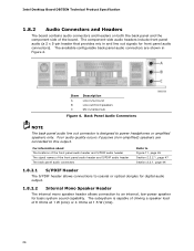
... Speaker Header The internal mono speaker header allows connection to an internal, low-power speaker for front panel audio connectors). The component-side audio headers include front panel audio (a 2 x 5-pin header that provides mic in and line out signals for basic system ... 1 W (rms) or 4 Ohms at 1.5 W (rms). 26 The available configurable back panel audio connectors are connected to power headphones or amplified speakers only. Intel Desktop Board DB75EN Technical Product Specification 1.8.2 Audio Connectors and Headers The board contains audio connectors and headers on both the...
... Speaker Header The internal mono speaker header allows connection to an internal, low-power speaker for front panel audio connectors). The component-side audio headers include front panel audio (a 2 x 5-pin header that provides mic in and line out signals for basic system ... 1 W (rms) or 4 Ohms at 1.5 W (rms). 26 The available configurable back panel audio connectors are connected to power headphones or amplified speakers only. Intel Desktop Board DB75EN Technical Product Specification 1.8.2 Audio Connectors and Headers The board contains audio connectors and headers on both the...
Technical Product Specification
Page 34
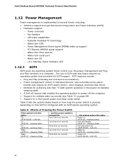
... bus and device enumeration) • Power management control of a computer. sleeping state) ...and the power switch is pressed for a front panel power and sleep mode switch Table 8 lists the system states based on how long the power switch is pressed, depending on (ACPI G0... (ACPI G1 - Off (ACPI G2/G5 - working state) On (ACPI G0 - sleeping state) Fail safe power-off ) 34 Intel Desktop Board DB75EN Technical Product Specification 1.12 Power Management Power management is implemented at several levels, including: • Software support through Advanced Configuration and Power ...
... bus and device enumeration) • Power management control of a computer. sleeping state) ...and the power switch is pressed for a front panel power and sleep mode switch Table 8 lists the system states based on how long the power switch is pressed, depending on (ACPI G0... (ACPI G1 - Off (ACPI G2/G5 - working state) On (ACPI G0 - sleeping state) Fail safe power-off ) 34 Intel Desktop Board DB75EN Technical Product Specification 1.12 Power Management Power management is implemented at several levels, including: • Software support through Advanced Configuration and Power ...

Technical Product Specification
Page 38
... specification can participate in the S3 sleep-state, the computer will appear to be off (the power supply is off, and the front panel LED is amber if dual colored, or off if single colored.) When signaled by a wake-up the computer. Failure to provide adequate ... S3 (Suspend-toRAM) sleep-state. While in power management and can damage the power supply. The use of the computer through a network. Intel Desktop Board DB75EN Technical Product Specification 1.12.2.3 LAN Wake Capabilities CAUTION For LAN wake capabilities, the +5 V standby line for the power supply must be capable...
... specification can participate in the S3 sleep-state, the computer will appear to be off (the power supply is off, and the front panel LED is amber if dual colored, or off if single colored.) When signaled by a wake-up the computer. Failure to provide adequate ... S3 (Suspend-toRAM) sleep-state. While in power management and can damage the power supply. The use of the computer through a network. Intel Desktop Board DB75EN Technical Product Specification 1.12.2.3 LAN Wake Capabilities CAUTION For LAN wake capabilities, the +5 V standby line for the power supply must be capable...

Technical Product Specification
Page 43
Table 11. Do not use these groups: • Back panel I/O connectors • Component-side connectors and headers (see page 45) 43 System Memory Map Address Range (decimal) Address Range (hex) 1024 K - 33550336 K 100000 - ...memory manager software) Extended conventional memory Conventional memory 2.2 Connectors and Headers CAUTION Only the following connectors and headers have overcurrent protection: back panel and front panel USB, and PS/2. The connectors can be divided into these connectors or headers to power devices external to the PCI Conventional bus). FFFFF...
Table 11. Do not use these groups: • Back panel I/O connectors • Component-side connectors and headers (see page 45) 43 System Memory Map Address Range (decimal) Address Range (hex) 1024 K - 33550336 K 100000 - ...memory manager software) Extended conventional memory Conventional memory 2.2 Connectors and Headers CAUTION Only the following connectors and headers have overcurrent protection: back panel and front panel USB, and PS/2. The connectors can be divided into these connectors or headers to power devices external to the PCI Conventional bus). FFFFF...

Technical Product Specification
Page 44
... Figure 10. Poor audio quality occurs if passive (non-amplified) speakers are connected to power headphones or amplified speakers only. Back Panel Connectors NOTE The back panel audio line out connector is designed to this output. 44 Intel Desktop Board DB75EN Technical Product Specification 2.2.1 Back Panel Connectors Figure 10 shows the location of the back...
... Figure 10. Poor audio quality occurs if passive (non-amplified) speakers are connected to power headphones or amplified speakers only. Back Panel Connectors NOTE The back panel audio line out connector is designed to this output. 44 Intel Desktop Board DB75EN Technical Product Specification 2.2.1 Back Panel Connectors Figure 10 shows the location of the back...

Technical Product Specification
Page 46
... intrusion header J LPC Debug header K TPM header L Main power connector (2 x 12) M Intel MEBX reset header N SATA 6.0 Gb/s connector (blue) O eSATA 3.0 Gb/s connector (red) P Alternate front panel power/sleep LED header Q Front panel header R SATA 3.0 connectors (black) S Front panel USB 3.0 connector (blue) T Front panel USB 2.0 header U Front panel USB 2.0 header V Serial port header W S/PDIF out header X Front...
... intrusion header J LPC Debug header K TPM header L Main power connector (2 x 12) M Intel MEBX reset header N SATA 6.0 Gb/s connector (blue) O eSATA 3.0 Gb/s connector (red) P Alternate front panel power/sleep LED header Q Front panel header R SATA 3.0 connectors (black) S Front panel USB 3.0 connector (blue) T Front panel USB 2.0 header U Front panel USB 2.0 header V Serial port header W S/PDIF out header X Front...

Technical Product Specification
Page 47
... Terminal Ready) 6 DSR (Data Set Ready) 8 CTS (Clear To Send) 10 Key (no pin) 10 FP_RETURN_L Table 16. Front Panel Audio Header for AC '97 Audio Pin Signal Name Pin Signal Name 1 MIC 3 MIC_BIAS 5 FP_OUT_R 2 AUD_GND 4 AUD_GND 6 FP_RETURN_R 7...7 Ground 8 9 KEY (no pin) 9 [Port 2] Left channel 10 [Port 2] SENSE_RETURN Table 15. Front Panel Audio Header for the Connectors and Headers Table 13. Technical Reference 2.2.2.1 Signal Tables for Intel HD Audio Pin Signal Name Pin Signal Name 1 [Port 1] Left channel 2 Ground 3 [Port 1] Right channel ...
... Terminal Ready) 6 DSR (Data Set Ready) 8 CTS (Clear To Send) 10 Key (no pin) 10 FP_RETURN_L Table 16. Front Panel Audio Header for AC '97 Audio Pin Signal Name Pin Signal Name 1 MIC 3 MIC_BIAS 5 FP_OUT_R 2 AUD_GND 4 AUD_GND 6 FP_RETURN_R 7...7 Ground 8 9 KEY (no pin) 9 [Port 2] Left channel 10 [Port 2] SENSE_RETURN Table 15. Front Panel Audio Header for the Connectors and Headers Table 13. Technical Reference 2.2.2.1 Signal Tables for Intel HD Audio Pin Signal Name Pin Signal Name 1 [Port 1] Left channel 2 Ground 3 [Port 1] Right channel ...

Technical Product Specification
Page 48
Front Panel USB 3.0 Connector Pin Signal Name 1 Vbus 2 IntA_P1_SSRX− Description Power USB3 ICC Port1 SuperSpeed Rx− 3 IntA_P1_SSRX+ USB3 ICC Port1 SuperSpeed Rx+ 4 GND 5 IntA_P1_SSTX− 6 ... 17 IntA_P2_SSRX+ 18 IntA_P2_SSRX− 19 Vbus USB3 ICC Port2 SuperSpeed Rx+ USB3 ICC Port2 SuperSpeed Rx+ Power 20 Key No pin Table 18. Intel Desktop Board DB75EN Technical Product Specification Table 17. SATA Connectors Pin Signal Name 1 Ground 2 TXP 3 TXN 4 Ground 5 RXN 6 RXP 7 Ground Table 19. S/PDIF Header Pin Signal Name...
Front Panel USB 3.0 Connector Pin Signal Name 1 Vbus 2 IntA_P1_SSRX− Description Power USB3 ICC Port1 SuperSpeed Rx− 3 IntA_P1_SSRX+ USB3 ICC Port1 SuperSpeed Rx+ 4 GND 5 IntA_P1_SSTX− 6 ... 17 IntA_P2_SSRX+ 18 IntA_P2_SSRX− 19 Vbus USB3 ICC Port2 SuperSpeed Rx+ USB3 ICC Port2 SuperSpeed Rx+ Power 20 Key No pin Table 18. Intel Desktop Board DB75EN Technical Product Specification Table 17. SATA Connectors Pin Signal Name 1 Ground 2 TXP 3 TXN 4 Ground 5 RXN 6 RXP 7 Ground Table 19. S/PDIF Header Pin Signal Name...

Technical Product Specification
Page 52
... (alt color) [In] Power switch Ground No pin Figure 12. Front Panel Header Pin Signal Name Description 1 HDD_POWER_LED Pull-up resistor (750 Ω) to a hard drive. Table 26 lists the signal names of the front panel header. Intel Desktop Board DB75EN Technical Product Specification 2.2.2.4 Front Panel Header This section describes the functions of the front...
... (alt color) [In] Power switch Ground No pin Figure 12. Front Panel Header Pin Signal Name Description 1 HDD_POWER_LED Pull-up resistor (750 Ω) to a hard drive. Table 26 lists the signal names of the front panel header. Intel Desktop Board DB75EN Technical Product Specification 2.2.2.4 Front Panel Header This section describes the functions of the front...

Technical Product Specification
Page 53
... a one - The switch must pass before the power supply will recognize another on/off signal. 2.2.2.5 Alternate Front Panel Power/Sleep LED Header Pins 1 and 3 of the front panel header. Table 29. Table 27 shows the possible states for a Two-Color Power LED LED State Description Off Power... colors listed in Table 27 and Table 28 are chassis-specific. 2.2.2.4.4 Power Switch Header Pins 6 and 8 can be connected to a front panel momentary-contact power switch. Table 27. Table 28 shows the possible states for a One-Color Power LED LED State Description Off Steady Green Power...
... a one - The switch must pass before the power supply will recognize another on/off signal. 2.2.2.5 Alternate Front Panel Power/Sleep LED Header Pins 1 and 3 of the front panel header. Table 29. Table 27 shows the possible states for a Two-Color Power LED LED State Description Off Power... colors listed in Table 27 and Table 28 are chassis-specific. 2.2.2.4.4 Power Switch Header Pins 6 and 8 can be connected to a front panel momentary-contact power switch. Table 27. Table 28 shows the possible states for a One-Color Power LED LED State Description Off Steady Green Power...

Technical Product Specification
Page 54
Figure 13. Intel Desktop Board DB75EN Technical Product Specification 2.2.2.6 Front Panel USB 2.0 Headers Figure 13 is fused. • Use only a front panel USB connector that conforms to the USB 2.0 specification for high-speed USB devices. Connection Diagram for the front panel USB 2.0 headers. NOTE • The +5 V DC power on the USB headers is a connection diagram for Front Panel USB 2.0 Headers 54
Figure 13. Intel Desktop Board DB75EN Technical Product Specification 2.2.2.6 Front Panel USB 2.0 Headers Figure 13 is fused. • Use only a front panel USB connector that conforms to the USB 2.0 specification for high-speed USB devices. Connection Diagram for the front panel USB 2.0 headers. NOTE • The +5 V DC power on the USB headers is a connection diagram for Front Panel USB 2.0 Headers 54
Technical Product Specification
Page 74
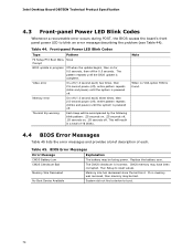
Intel Desktop Board DB75EN Technical Product Specification 4.3 Front-panel Power LED Blink Codes Whenever a recoverable error occurs during POST, the BIOS causes the board's front panel power LED to reset values. Thermal trip warning Each beep will result in progress Off when the update begins, then on ...Memory Size Decreased No Boot Device Available Explanation The battery may have been corrupted. Memory size has decreased since the last boot. Front-panel Power LED Blink Codes Type Pattern F2 Setup/F10 Boot Menu None Prompt BIOS update in a total of each ) three times, ...
Intel Desktop Board DB75EN Technical Product Specification 4.3 Front-panel Power LED Blink Codes Whenever a recoverable error occurs during POST, the BIOS causes the board's front panel power LED to reset values. Thermal trip warning Each beep will result in progress Off when the update begins, then on ...Memory Size Decreased No Boot Device Available Explanation The battery may have been corrupted. Memory size has decreased since the last boot. Front-panel Power LED Blink Codes Type Pattern F2 Setup/F10 Boot Menu None Prompt BIOS update in a total of each ) three times, ...


