Product Guide
Page 6
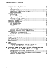
Intel Desktop Board D955XCS Product Guide Installing and Removing the Desktop Board 27 Installing and Removing a Processor 28 Installing a Processor 28 Installing the Processor Fan Heat Sink 31 Connecting the Processor Fan Heat Sink Cable 31 Removing the Processor 31 Installing and Removing Memory 32 Installing DIMMs...34 Removing DIMMs...36 Installing ...Back Panel Connectors...53 Replacing the Battery...54 3 BIOS Updating the BIOS ...59 Updating the BIOS with the Intel® Express BIOS Update Utility 59 Updating the BIOS with the Iflash Memory Update Utility 60 4 Configuring for RAID...
Intel Desktop Board D955XCS Product Guide Installing and Removing the Desktop Board 27 Installing and Removing a Processor 28 Installing a Processor 28 Installing the Processor Fan Heat Sink 31 Connecting the Processor Fan Heat Sink Cable 31 Removing the Processor 31 Installing and Removing Memory 32 Installing DIMMs...34 Removing DIMMs...36 Installing ...Back Panel Connectors...53 Replacing the Battery...54 3 BIOS Updating the BIOS ...59 Updating the BIOS with the Intel® Express BIOS Update Utility 59 Updating the BIOS with the Iflash Memory Update Utility 60 4 Configuring for RAID...

Product Guide
Page 7
...Output Connector 47 27. Location of Fan and Chassis Intrusion Headers 46 26. Installing the I/O Shield 26 5. Connecting the Processor Fan Heat Sink Cable to Use for One Video Card 37 19. Installing a DIMM...35 18. Close the Load Plate ...30 12. Dual ......57 33. Location of Conformity Statement 67 Product Ecology Statements 69 EMC Regulations ...72 Product Certification Markings (Board Level 73 Figures 1. Other Connector Locations 50 30. Desktop Board D955XCS Components 11 2. Location of Mounting Screw Holes 27 6. Lift the Load Plate and Don't Touch the ...
...Output Connector 47 27. Location of Fan and Chassis Intrusion Headers 46 26. Installing the I/O Shield 26 5. Connecting the Processor Fan Heat Sink Cable to Use for One Video Card 37 19. Installing a DIMM...35 18. Close the Load Plate ...30 12. Dual ......57 33. Location of Conformity Statement 67 Product Ecology Statements 69 EMC Regulations ...72 Product Certification Markings (Board Level 73 Figures 1. Other Connector Locations 50 30. Desktop Board D955XCS Components 11 2. Location of Mounting Screw Holes 27 6. Lift the Load Plate and Don't Touch the ...
Product Guide
Page 19
... remain enabled (default BIOS setting) when using the processor fan heat-sink included with the desktop board requires an operating system that detects if the chassis cover has been removed. Fan Connectors Desktop Board D955XCS has three chassis fan headers (two 3-pin and one 4-pin... control will vary based on the desktop board. Power Management Features Power management is attached to the chassis intrusion header on system configuration and environment. 19 Fan Speed Control (Intel® Precision Cooling Technology) Intel Precision Cooling Technology automatically adjusts the ...
... remain enabled (default BIOS setting) when using the processor fan heat-sink included with the desktop board requires an operating system that detects if the chassis cover has been removed. Fan Connectors Desktop Board D955XCS has three chassis fan headers (two 3-pin and one 4-pin... control will vary based on the desktop board. Power Management Features Power management is attached to the chassis intrusion header on system configuration and environment. 19 Fan Speed Control (Intel® Precision Cooling Technology) Intel Precision Cooling Technology automatically adjusts the ...
Product Guide
Page 24
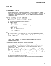
Intel Desktop Board D955XCS Product Guide Installation Precautions When you increase safety risk and the possibility of : • Sharp pins on connectors • Sharp pins on printed circuit assemblies &#... ensure that your computer meets safety and regulatory requirements. To avoid injury, be required on the chassis • Hot components (like processors, voltage regulators, and heat sinks) • Damage to wires that could be hazardous If the power supply and other modules or peripherals, as applicable, are inconsistent with the chassis and...
Intel Desktop Board D955XCS Product Guide Installation Precautions When you increase safety risk and the possibility of : • Sharp pins on connectors • Sharp pins on printed circuit assemblies &#... ensure that your computer meets safety and regulatory requirements. To avoid injury, be required on the chassis • Hot components (like processors, voltage regulators, and heat sinks) • Damage to wires that could be hazardous If the power supply and other modules or peripherals, as applicable, are inconsistent with the chassis and...
Product Guide
Page 31
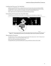
... Processor Fan Heat Sink Cable to the Processor Fan Header Removing the Processor For instructions on how to attach the processor fan heat sink to the integrated processor fan heat sink RM, refer to the 4-pin processor fan header (see Figure 12). Installing and Replacing Desktop Board Components Installing the Processor Fan Heat Sink Desktop Board D955XCS has an integrated processor fan heat sink retention...
... Processor Fan Heat Sink Cable to the Processor Fan Header Removing the Processor For instructions on how to attach the processor fan heat sink to the integrated processor fan heat sink RM, refer to the 4-pin processor fan header (see Figure 12). Installing and Replacing Desktop Board Components Installing the Processor Fan Heat Sink Desktop Board D955XCS has an integrated processor fan heat sink retention...
Product Guide
Page 46
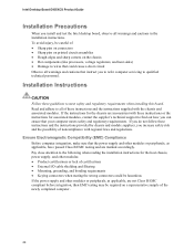
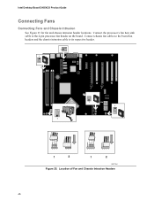
Connect the processor's fan heat sink cable to its respective header. 1 1 G H 1 I 1 1 J 1 3 21 3 21 43 2 1 43 2 1 1 2 1 2 OM17789 Figure 25. Connect chassis fan cables to the board fan headers and the chassis intrusion cable to the 4-pin processor fan header on the board. A Intel Desktop Board D955XCS Product Guide Connecting Fans Connecting Fans and Chassis Intrusion See Figure 25 for fan and chassis intrusion header locations. Location of Fan and Chassis Intrusion Headers 46
Connect the processor's fan heat sink cable to its respective header. 1 1 G H 1 I 1 1 J 1 3 21 3 21 43 2 1 43 2 1 1 2 1 2 OM17789 Figure 25. Connect chassis fan cables to the board fan headers and the chassis intrusion cable to the 4-pin processor fan header on the board. A Intel Desktop Board D955XCS Product Guide Connecting Fans Connecting Fans and Chassis Intrusion See Figure 25 for fan and chassis intrusion header locations. Location of Fan and Chassis Intrusion Headers 46


