Product Guide
Page 3
... Storage Technology) Requires Microsoft Windows* XP or 2000 and SATA Hard Drive(s): information about BIOS error messages and beep codes. NOTE Notes call attention to important information. Preface This Product Guide gives information about how to prevent damage to hardware or loss of data. Intended Uses All Intel desktop boards are arranged as follows: 1 Desktop Board Features: a summary of product features. 2 Installing and Replacing Desktop Board Components: instructions on how to install the desktop board...
... Storage Technology) Requires Microsoft Windows* XP or 2000 and SATA Hard Drive(s): information about BIOS error messages and beep codes. NOTE Notes call attention to important information. Preface This Product Guide gives information about how to prevent damage to hardware or loss of data. Intended Uses All Intel desktop boards are arranged as follows: 1 Desktop Board Features: a summary of product features. 2 Installing and Replacing Desktop Board Components: instructions on how to install the desktop board...
Product Guide
Page 4
... some common terms used in blue text) • Back panel audio covers • Quick Reference poster • Integration Guide poster • Printed Product Guide • Configuration and battery caution statement label • Game flier iv Intel Desktop Board D955XCS Product Guide Terminology The table below gives descriptions to 2x4 power adapter • Intel® Express Installer driver CD-ROM • Intel Express Installer Extreme Series software DVD-ROM • One Intel® Matrix Storage Technology RAID Driver floppy disk (in black text...
... some common terms used in blue text) • Back panel audio covers • Quick Reference poster • Integration Guide poster • Printed Product Guide • Configuration and battery caution statement label • Game flier iv Intel Desktop Board D955XCS Product Guide Terminology The table below gives descriptions to 2x4 power adapter • Intel® Express Installer driver CD-ROM • Intel Express Installer Extreme Series software DVD-ROM • One Intel® Matrix Storage Technology RAID Driver floppy disk (in black text...
Product Guide
Page 5
... Serial ATA and IDE Auto Configuration 18 PCI and PCI Express* Auto Configuration 18 Security Passwords...18 Chassis Intrusion...19 Power Management Features 19 ACPI...19 Fan Connectors...19 Fan Speed Control (Intel® Precision Cooling Technology 19 Suspend to RAM (Instantly Available PC Technology 20 Resume on Ring ...21 Wake from USB ...21 Wake from PS/2* Keyboard/Mouse 21 PME# Wakeup Support 21 Speaker...21 Battery...21 Real-Time Clock...21 2 Installing and Replacing Desktop Board Components Before You Begin ...23 Installation Precautions ...24 Installation Instructions...
... Serial ATA and IDE Auto Configuration 18 PCI and PCI Express* Auto Configuration 18 Security Passwords...18 Chassis Intrusion...19 Power Management Features 19 ACPI...19 Fan Connectors...19 Fan Speed Control (Intel® Precision Cooling Technology 19 Suspend to RAM (Instantly Available PC Technology 20 Resume on Ring ...21 Wake from USB ...21 Wake from PS/2* Keyboard/Mouse 21 PME# Wakeup Support 21 Speaker...21 Battery...21 Real-Time Clock...21 2 Installing and Replacing Desktop Board Components Before You Begin ...23 Installation Precautions ...24 Installation Instructions...
Product Guide
Page 6
... Cables...48 Other Connectors...50 Setting the BIOS Configuration Jumper 51 Clearing Passwords ...52 Back Panel Connectors...53 Replacing the Battery...54 3 BIOS Updating the BIOS ...59 Updating the BIOS with the Intel® Express BIOS Update Utility 59 Updating the BIOS with the Iflash Memory Update Utility 60 4 Configuring for RAID (Intel® Matrix Storage Technology) Requires Microsoft Windows* XP or 2000 and SATA Hard Drive(s) Configuring the BIOS for Intel Matrix Storage Technology 63 Creating Your RAID Set 63 Loading the Intel Matrix Storage Technology RAID Drivers and Software...
... Cables...48 Other Connectors...50 Setting the BIOS Configuration Jumper 51 Clearing Passwords ...52 Back Panel Connectors...53 Replacing the Battery...54 3 BIOS Updating the BIOS ...59 Updating the BIOS with the Intel® Express BIOS Update Utility 59 Updating the BIOS with the Iflash Memory Update Utility 60 4 Configuring for RAID (Intel® Matrix Storage Technology) Requires Microsoft Windows* XP or 2000 and SATA Hard Drive(s) Configuring the BIOS for Intel Matrix Storage Technology 63 Creating Your RAID Set 63 Loading the Intel Matrix Storage Technology RAID Drivers and Software...

Product Guide
Page 7
... Panel Connectors 53 32. F2 Key ...59 vii Installing the I/O Shield 26 5. Remove the Processor from the Protective Processor Cover/Do Not Touch 29 10. Use DDR2 DIMMs ...34 17. Auxiliary Power Output Connector 47 27. Install the Processor ...30 11. Dual Configuration Example 3 33 16. Dual Configuration Example 2 32 15. Other Connector Locations 50 30. Removing the PCI Express x16 Card 38 20. Connecting 2x12 Power Supply Cables 49 29. Desktop Board D955XCS Components 11 2. Back Panel LAN Port LED Locations 16 3. Removing the Battery...
... Panel Connectors 53 32. F2 Key ...59 vii Installing the I/O Shield 26 5. Remove the Processor from the Protective Processor Cover/Do Not Touch 29 10. Use DDR2 DIMMs ...34 17. Auxiliary Power Output Connector 47 27. Install the Processor ...30 11. Dual Configuration Example 3 33 16. Dual Configuration Example 2 32 15. Other Connector Locations 50 30. Removing the PCI Express x16 Card 38 20. Connecting 2x12 Power Supply Cables 49 29. Desktop Board D955XCS Components 11 2. Back Panel LAN Port LED Locations 16 3. Removing the Battery...
Product Guide
Page 9
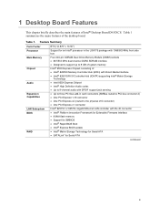
...; Intel® 82801GR I/O Controller Hub (ICH7R) supporting Intel® Matrix Storage Technology • Intel 955X Express Chipset • Intel® High Definition Audio codec • Up to 8-channel audio with SPDIF support jack sensing • Up to three PCI bus add-in card connectors (SMBus routed to PCI bus connector 2) • One PCI Express* x16 connector • One PCI Express x4 (routed to 8 GB of system memory Intel® 955X Express Chipset consisting of Intel® Desktop Board D955XCS. Table 1 summarizes the major features of the desktop board.
...; Intel® 82801GR I/O Controller Hub (ICH7R) supporting Intel® Matrix Storage Technology • Intel 955X Express Chipset • Intel® High Definition Audio codec • Up to 8-channel audio with SPDIF support jack sensing • Up to three PCI bus add-in card connectors (SMBus routed to PCI bus connector 2) • One PCI Express* x16 connector • One PCI Express x4 (routed to 8 GB of system memory Intel® 955X Express Chipset consisting of Intel® Desktop Board D955XCS. Table 1 summarizes the major features of the desktop board.
Product Guide
Page 10
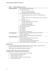
... to RAM (STR) • Wake on USB, PCI, PCI Express, PS/2, LAN, and front panel Hardware monitor with: • Four fan sensing inputs used to monitor fan activity • Remote diode temperature sensing • Intel® Precision Cooling Technology fan speed control • Voltage sensing to detect out of range values Related Links For more information about Intel Desktop Board D955XCS, including the Technical Product Specification (TPS), BIOS updates, and device drivers, go to eight Serial ATA channels (one device per channel) - Intel Desktop Board D955XCS Product Guide...
... to RAM (STR) • Wake on USB, PCI, PCI Express, PS/2, LAN, and front panel Hardware monitor with: • Four fan sensing inputs used to monitor fan activity • Remote diode temperature sensing • Intel® Precision Cooling Technology fan speed control • Voltage sensing to detect out of range values Related Links For more information about Intel Desktop Board D955XCS, including the Technical Product Specification (TPS), BIOS updates, and device drivers, go to eight Serial ATA channels (one device per channel) - Intel Desktop Board D955XCS Product Guide...
Product Guide
Page 12
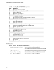
... connector PCI Express x4 connector (routed to a physical x16 connector) PCI bus add-in card connectors (four) Auxiliary power output header IEEE 1394a header (blue) IEEE 1394b header (pink) Serial ATA connectors (four, blue, Silicon Image) Auxiliary front chassis fan header (4-pin, fan speed control) Alternate power LED header Front panel header Front chassis fan (fan speed control) Diskette drive connector BIOS configuration jumper Alternate power connector (1x4) Processor socket (LGA775) 12 V power connector (2x4) Processor fan header (4-pin, fan speed control) Rear chassis fan header (fan...
... connector PCI Express x4 connector (routed to a physical x16 connector) PCI bus add-in card connectors (four) Auxiliary power output header IEEE 1394a header (blue) IEEE 1394b header (pink) Serial ATA connectors (four, blue, Silicon Image) Auxiliary front chassis fan header (4-pin, fan speed control) Alternate power LED header Front panel header Front chassis fan (fan speed control) Diskette drive connector BIOS configuration jumper Alternate power connector (1x4) Processor socket (LGA775) 12 V power connector (2x4) Processor fan header (4-pin, fan speed control) Rear chassis fan header (fan...
Product Guide
Page 14
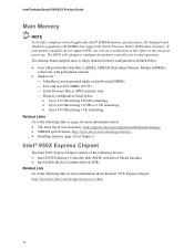
... attempt to this effect on the screen at power up. The desktop board supports dual or single channel memory configurations defined below: • Four 240-pin Double Data Rate 2 (DDR2) SDRAM Dual Inline Memory Module (DIMMs) connectors with DIMMs that support the Serial Presence Detect (SPD) data structure. Intel Desktop Board D955XCS Product Guide Main Memory NOTE To be fully compliant with all applicable Intel® SDRAM memory specifications, the desktop board should be populated with gold...
... attempt to this effect on the screen at power up. The desktop board supports dual or single channel memory configurations defined below: • Four 240-pin Double Data Rate 2 (DDR2) SDRAM Dual Inline Memory Module (DIMMs) connectors with DIMMs that support the Serial Presence Detect (SPD) data structure. Intel Desktop Board D955XCS Product Guide Main Memory NOTE To be fully compliant with all applicable Intel® SDRAM memory specifications, the desktop board should be populated with gold...
Product Guide
Page 16
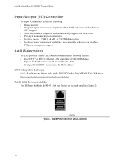
... 2. Back Panel LAN Port LED Locations 16 Intel Desktop Board D955XCS Product Guide Input/Output (I/O) Controller The super I/O controller features the following: • One serial port • One parallel port with Extended Capabilities Port (ECP) and Enhanced Parallel Port (EPP) support • Serial IRQ interface compatible with serialized IRQ support for PCI systems • PS/2-style mouse and keyboard interfaces • Interface for one 1.2 MB, 1.44 MB, or 2.88 MB diskette drive • Intelligent power management...
... 2. Back Panel LAN Port LED Locations 16 Intel Desktop Board D955XCS Product Guide Input/Output (I/O) Controller The super I/O controller features the following: • One serial port • One parallel port with Extended Capabilities Port (ECP) and Enhanced Parallel Port (EPP) support • Serial IRQ interface compatible with serialized IRQ support for PCI systems • PS/2-style mouse and keyboard interfaces • Interface for one 1.2 MB, 1.44 MB, or 2.88 MB diskette drive • Intelligent power management...
Product Guide
Page 18
... Power-On Self-Test (POST), the BIOS Setup program, the PCI and IDE auto-configuration utilities, and the video BIOS. The password prompt is displayed before the computer is set , you must enter either password to the physical x16 connector) • One PCI Express x1 add-in card • Four PCI bus add-in Chapter 2. When booting from a Serial ATA device, Serial ATA connector 0 is the first boot device and Serial ATA connector 3 is set, pressing at the password prompt of Setup gives the user...
... Power-On Self-Test (POST), the BIOS Setup program, the PCI and IDE auto-configuration utilities, and the video BIOS. The password prompt is displayed before the computer is set , you must enter either password to the physical x16 connector) • One PCI Express x1 add-in card • Four PCI bus add-in Chapter 2. When booting from a Serial ATA device, Serial ATA connector 0 is the first boot device and Serial ATA connector 3 is set, pressing at the password prompt of Setup gives the user...
Product Guide
Page 19
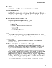
Fan Connectors Desktop Board D955XCS has three chassis fan headers (two 3-pin and one 4-pin) and one processor fan header (4-pin). It is not a self controlled fan. Desktop Board Features Related Links: For instructions on resetting the password, see Clearing Passwords on page 46 for the location of the chassis intrusion header. The processor and chassis fan speed control features can be connected to the chassis intrusion header on the desktop board. The overall system noise reduction will result in chassis fans always operating at the minimum necessary speeds. See...
Fan Connectors Desktop Board D955XCS has three chassis fan headers (two 3-pin and one 4-pin) and one processor fan header (4-pin). It is not a self controlled fan. Desktop Board Features Related Links: For instructions on resetting the password, see Clearing Passwords on page 46 for the location of the chassis intrusion header. The processor and chassis fan speed control features can be connected to the chassis intrusion header on the desktop board. The overall system noise reduction will result in chassis fans always operating at the minimum necessary speeds. See...
Product Guide
Page 20
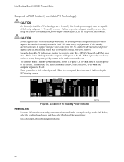
... signaled by the LED turning amber. This includes the memory modules and PCI bus connectors, even when the computer appears to be capable of the Standby Power Indicator OM17779 Related Links For more information on the front panel, the sleep state is standby power to support multiple wake events from the PCI and/or USB buses exceeds power supply capacity, the desktop board may lose register settings stored in...
... signaled by the LED turning amber. This includes the memory modules and PCI bus connectors, even when the computer appears to be capable of the Standby Power Indicator OM17779 Related Links For more information on the front panel, the sleep state is standby power to support multiple wake events from the PCI and/or USB buses exceeds power supply capacity, the desktop board may lose register settings stored in...
Product Guide
Page 23
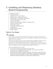
...front panel power button is not available, you how to: • Install the I/O shield • Install and remove the desktop board • Install and remove a processor and memory • Install and remove a PCI Express x16 add-in card • Connect the IDE and Serial ATA cables • Connect internal headers • Install the rear and front panel USB/IEEE 1394/audio solutions • Connect fan and power cables • Identify other connectors • Set the BIOS configuration jumper • Clear passwords • Identify back panel connectors • Replace the battery Before...
...front panel power button is not available, you how to: • Install the I/O shield • Install and remove the desktop board • Install and remove a processor and memory • Install and remove a PCI Express x16 add-in card • Connect the IDE and Serial ATA cables • Connect internal headers • Install the rear and front panel USB/IEEE 1394/audio solutions • Connect fan and power cables • Identify other connectors • Set the BIOS configuration jumper • Clear passwords • Identify back panel connectors • Replace the battery Before...
Product Guide
Page 51
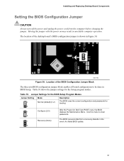
... Setup program modes. Use this menu to be done in unreliable computer operation. The location of the desktop board's BIOS configuration jumper is shown in the 1 Recovery (None) event of the BIOS Configuration Jumper Block The three-pin BIOS configuration jumper block enables all board configurations to clear passwords. 3 The BIOS recovers data from the computer before changing the jumper. Location of a failed BIOS update. 3 51 Moving the jumper with the power on may result in BIOS Setup. Table 10. Installing and Replacing Desktop Board Components Setting the BIOS...
... Setup program modes. Use this menu to be done in unreliable computer operation. The location of the desktop board's BIOS configuration jumper is shown in the 1 Recovery (None) event of the BIOS Configuration Jumper Block The three-pin BIOS configuration jumper block enables all board configurations to clear passwords. 3 The BIOS recovers data from the computer before changing the jumper. Location of a failed BIOS update. 3 51 Moving the jumper with the power on may result in BIOS Setup. Table 10. Installing and Replacing Desktop Board Components Setting the BIOS...
Product Guide
Page 52
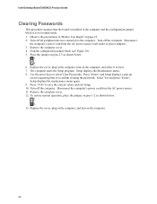
... . Remove the computer cover. 12. Use the arrow keys to save the current values and exit Setup. 10. Place the jumper on pins 1-2 as shown below . 1 3 13. Setup displays the Maintenance menu. 8. Intel Desktop Board D955XCS Product Guide Clearing Passwords This procedure assumes that you confirm clearing the password. Disconnect the computer's power cord from the AC power source. 11. Replace the cover, plug in the computer and the configuration jumper block is installed in...
... . Remove the computer cover. 12. Use the arrow keys to save the current values and exit Setup. 10. Place the jumper on pins 1-2 as shown below . 1 3 13. Setup displays the Maintenance menu. 8. Intel Desktop Board D955XCS Product Guide Clearing Passwords This procedure assumes that you confirm clearing the password. Disconnect the computer's power cord from the AC power source. 11. Replace the cover, plug in the computer and the configuration jumper block is installed in...
Product Guide
Page 53
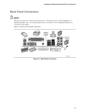
Poor audio quality may occur if passive (non-amplified) speakers are connected to power either headphones or amplified speakers only. Back Panel Connectors OM17797 53 Installing and Replacing Desktop Board Components Back Panel Connectors NOTE The line out connector, located on the back panel, is designed to this output. IEEE 1394a Line In Coaxial Line Out Optical Line Out (Toslink) Figure 31. Figure 31 shows the back panel connectors.
Poor audio quality may occur if passive (non-amplified) speakers are connected to power either headphones or amplified speakers only. Back Panel Connectors OM17797 53 Installing and Replacing Desktop Board Components Back Panel Connectors NOTE The line out connector, located on the back panel, is designed to this output. IEEE 1394a Line In Coaxial Line Out Optical Line Out (Toslink) Figure 31. Figure 31 shows the back panel connectors.
Product Guide
Page 60
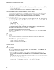
....intel.com/support/motherboards/desktop Navigate to make sure the update was saved. Obtaining the BIOS Update File You can obtain the BIOS update file through your computer supplier or by using the BIOS update file. NOTE Review the instructions distributed with the update files will automatically update your hard drive where it was successful. The BIOS update file is complete, the monitor will display a message telling you to complete the BIOS update. The BIOS update file contains: • New BIOS files • BIOS recovery files • Intel Flash Memory Update Utility...
....intel.com/support/motherboards/desktop Navigate to make sure the update was saved. Obtaining the BIOS Update File You can obtain the BIOS update file through your computer supplier or by using the BIOS update file. NOTE Review the instructions distributed with the update files will automatically update your hard drive where it was successful. The BIOS update file is complete, the monitor will display a message telling you to complete the BIOS update. The BIOS update file contains: • New BIOS files • BIOS recovery files • Intel Flash Memory Update Utility...
Product Guide
Page 63
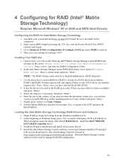
... the Option ROM user interface by booting from the Internet at http://support.intel.com/support/motherboards/desktop/. Begin Windows Setup by pressing or going to enter the RAID Configuration Utility. Install the Intel Matrix Storage Console software via the Intel Express Installer CD included with your desktop board or after the Power-On-Self-Test (POST) memory tests begin. 3. Go to Create Volume. 8. Use the arrow keys to select RAID 0 or RAID 1 (if only two SATA drives are available), RAID 5 and RAID 10 (these options...
... the Option ROM user interface by booting from the Internet at http://support.intel.com/support/motherboards/desktop/. Begin Windows Setup by pressing or going to enter the RAID Configuration Utility. Install the Intel Matrix Storage Console software via the Intel Express Installer CD included with your desktop board or after the Power-On-Self-Test (POST) memory tests begin. 3. Go to Create Volume. 8. Use the arrow keys to select RAID 0 or RAID 1 (if only two SATA drives are available), RAID 5 and RAID 10 (these options...

Product Guide
Page 64
Intel Desktop Board D955XCS Product Guide Setting Up a "RAID Ready" System The Intel Matrix Storage Technology Console software offers the flexibility to upgrade from this section: "Configuring the BIOS for Intel Matrix Storage Technology" and "Loading the Intel Matrix Storage Technology RAID Drivers and Software". Once additional SATA drives have been added, open the Intel Matrix Storage Technology Console Software and follow the directions to update to the system. Follow the steps described in the headings from a single Serial ATA drive to RAID without reinstalling...
Intel Desktop Board D955XCS Product Guide Setting Up a "RAID Ready" System The Intel Matrix Storage Technology Console software offers the flexibility to upgrade from this section: "Configuring the BIOS for Intel Matrix Storage Technology" and "Loading the Intel Matrix Storage Technology RAID Drivers and Software". Once additional SATA drives have been added, open the Intel Matrix Storage Technology Console Software and follow the directions to update to the system. Follow the steps described in the headings from a single Serial ATA drive to RAID without reinstalling...


