

Product Specification
Page 7
...; Rapid BIOS Boot 86 3.7.1 Peripheral Selection and Configuration 86 3.7.2 Intel Rapid BIOS Boot 86 3.8 BIOS Security Features 87 4 Error Messages and Beep Codes 4.1 Speaker ...89 4.2 BIOS Beep Codes...89 4.3 BIOS Error Messages 89 4.4 Port 80h POST Codes 90 Figures 1. Detailed System Memory Address Map 46 17. Manufacturing Options 11 3. Components Shown in Figure 1 13 4. Board Dimensions...68 25. Example of a Processor Heatsink for 6-Channel (5.1) Audio Subsystem 55 19. LAN Connector LED Locations 31 14. Desktop Board Components 12 2. Back Panel Connectors for...
...; Rapid BIOS Boot 86 3.7.1 Peripheral Selection and Configuration 86 3.7.2 Intel Rapid BIOS Boot 86 3.8 BIOS Security Features 87 4 Error Messages and Beep Codes 4.1 Speaker ...89 4.2 BIOS Beep Codes...89 4.3 BIOS Error Messages 89 4.4 Port 80h POST Codes 90 Figures 1. Detailed System Memory Address Map 46 17. Manufacturing Options 11 3. Components Shown in Figure 1 13 4. Board Dimensions...68 25. Example of a Processor Heatsink for 6-Channel (5.1) Audio Subsystem 55 19. LAN Connector LED Locations 31 14. Desktop Board Components 12 2. Back Panel Connectors for...

Product Specification
Page 8
... 41. BIOS Setup Program Function Keys 82 44. Supervisor and User Password Functions 87 46. Intel Desktop Board D955XBK Technical Product Specification 5. DMA Channels ...47 11. ATAPI CD-ROM Connector (Optional 58 19. Main Power Connector 61 27. States for Components 75 38. Boot Device Menu Options 85 45. Wake-up Devices and Events 39 9. Interrupts ...50 14. Back Panel Connectors Shown in Figure 17 54 16. Chassis Intrusion Connector 59 23. Processor Power Connector (2 x 2 Pin 61 29. Auxiliary Front Panel Power/Sleep LED Connector 62...
... 41. BIOS Setup Program Function Keys 82 44. Supervisor and User Password Functions 87 46. Intel Desktop Board D955XBK Technical Product Specification 5. DMA Channels ...47 11. ATAPI CD-ROM Connector (Optional 58 19. Main Power Connector 61 27. States for Components 75 38. Boot Device Menu Options 85 45. Wake-up Devices and Events 39 9. Interrupts ...50 14. Back Panel Connectors Shown in Figure 17 54 16. Chassis Intrusion Connector 59 23. Processor Power Connector (2 x 2 Pin 61 29. Auxiliary Front Panel Power/Sleep LED Connector 62...
Product Specification
Page 10
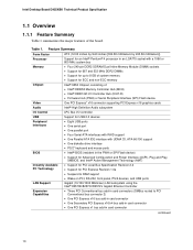
...) Flash device One PCI Express* x16 connector supporting PCI Express x16 graphics cards Intel® High Definition Audio subsystem I/O Control USB Peripheral Interfaces BIOS Instantly Available PC Technology LAN Support Expansion Capabilities LPC Bus I/O controller Support for USB 2.0 devices • Eight USB ports • One serial port • One parallel port • Four Serial ATA interfaces with RAID support • One Parallel ATA IDE interface with a 1066 or 800 MHz system bus Memory Chipset Video Audio • Four 240-pin DDR2 SDRAM Dual Inline Memory Module (DIMM) sockets...
...) Flash device One PCI Express* x16 connector supporting PCI Express x16 graphics cards Intel® High Definition Audio subsystem I/O Control USB Peripheral Interfaces BIOS Instantly Available PC Technology LAN Support Expansion Capabilities LPC Bus I/O controller Support for USB 2.0 devices • Eight USB ports • One serial port • One parallel port • Four Serial ATA interfaces with RAID support • One Parallel ATA IDE interface with a 1066 or 800 MHz system bus Memory Chipset Video Audio • Four 240-pin DDR2 SDRAM Dual Inline Memory Module (DIMM) sockets...

Product Specification
Page 11
... PCI Express x16/x4 bus add-in card connectors ATAPI CD-ROM connector A 1 x 4-pin ATAPI-style connector for connecting an internal ATAPI CD-ROM drive to the audio mixer Audio Subsystem Intel High Definition Audio subsystem in one of the following connectors for providing +12 V power to the processor voltage regulator: • 2 x 4-pin (requires a power supply with three analog audio outputs using the Sigmatel 9221 audio codec • 6-channel (5.1) audio subsystem with a dual-rail 2 x 4 power cable) • 2 x 2-pin SCSI Hard Drive Activity LED Connector Allows add-in hard drive...
... PCI Express x16/x4 bus add-in card connectors ATAPI CD-ROM connector A 1 x 4-pin ATAPI-style connector for connecting an internal ATAPI CD-ROM drive to the audio mixer Audio Subsystem Intel High Definition Audio subsystem in one of the following connectors for providing +12 V power to the processor voltage regulator: • 2 x 4-pin (requires a power supply with three analog audio outputs using the Sigmatel 9221 audio codec • 6-channel (5.1) audio subsystem with a dual-rail 2 x 4 power cable) • 2 x 2-pin SCSI Hard Drive Activity LED Connector Allows add-in hard drive...

Product Specification
Page 14
...-R) Firmware Hub (FWH) -- Intel Desktop Board D955XBK Technical Product Specification 1.1.4 Block Diagram Figure 2 is a block diagram of the major functional areas of the board. or -SPI Flash Device Intel 955X Chipset LPC Bus SMBus Channel A DIMMs (2) Dual-Channel Memory Bus SMBus TPM Component (Optional) High Definition Audio Link Channel B DIMMs (2) SATA IDE Interface SATA IDE Connectors (4) IEEE-1394a/b Connectors (Optional) IEEE-1394a/b Controller (Optional) PCI Bus Front Panel Mic In Front Panel Line Out SATA RAID Connectors (4) (Optional) PCI Slot 1 Discrete SATA RAID...
...-R) Firmware Hub (FWH) -- Intel Desktop Board D955XBK Technical Product Specification 1.1.4 Block Diagram Figure 2 is a block diagram of the major functional areas of the board. or -SPI Flash Device Intel 955X Chipset LPC Bus SMBus Channel A DIMMs (2) Dual-Channel Memory Bus SMBus TPM Component (Optional) High Definition Audio Link Channel B DIMMs (2) SATA IDE Interface SATA IDE Connectors (4) IEEE-1394a/b Connectors (Optional) IEEE-1394a/b Controller (Optional) PCI Bus Front Panel Mic In Front Panel Line Out SATA RAID Connectors (4) (Optional) PCI Slot 1 Discrete SATA RAID...

Product Specification
Page 23
... hard drive controller to , either the add-in hard drive controller or the onboard IDE controller (Parallel ATA or Serial ATA). This provides the highest performance with data striping (RAID 0) into CMOS RAM at power-on separate disk drives. distributed parity. RAID 5 requires the use of three years. When the computer is not plugged into a wall socket, the battery has an estimated life of three or four drives. 1.5.2.4 SCSI Hard Drive Activity LED Connector (Optional) The SCSI hard drive...
... hard drive controller to , either the add-in hard drive controller or the onboard IDE controller (Parallel ATA or Serial ATA). This provides the highest performance with data striping (RAID 0) into CMOS RAM at power-on separate disk drives. distributed parity. RAID 5 requires the use of three years. When the computer is not plugged into a wall socket, the battery has an estimated life of three or four drives. 1.5.2.4 SCSI Hard Drive Activity LED Connector (Optional) The SCSI hard drive...

Product Specification
Page 53
... fans and internal peripherals. A fault in the load presented by the external devices could cause damage to the computer's chassis. This section describes the board's connectors. The connectors can be divided into these connectors to power devices external to the computer, the power cable, and the external devices themselves. Technical Reference 2.7 Connectors CAUTION Only the following connectors have overcurrent protection: back panel USB, front panel USB, and PS/2. Do not use...
... fans and internal peripherals. A fault in the load presented by the external devices could cause damage to the computer's chassis. This section describes the board's connectors. The connectors can be divided into these connectors to power devices external to the computer, the power cable, and the external devices themselves. Technical Reference 2.7 Connectors CAUTION Only the following connectors have overcurrent protection: back panel USB, front panel USB, and PS/2. Do not use...

Product Specification
Page 81
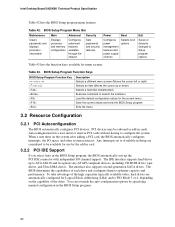
... PCI auto-configuration utility, and Plug and Play support. When the BIOS Setup configuration jumper is set to configure mode and the computer is poweredup, the BIOS compares the CPU version and the microcode version in either a Firmware Hub (FWH) or a Serial Peripheral Interface (SPI) Flash device and can be updated using a disk-based program. The BIOS Setup program can be used to put the board in configure mode. The menu bar is accessed by pressing the key after the Power-On Self-Test (POST) memory...
... PCI auto-configuration utility, and Plug and Play support. When the BIOS Setup configuration jumper is set to configure mode and the computer is poweredup, the BIOS compares the CPU version and the microcode version in either a Firmware Hub (FWH) or a Serial Peripheral Interface (SPI) Flash device and can be updated using a disk-based program. The BIOS Setup program can be used to put the board in configure mode. The menu bar is accessed by pressing the key after the Power-On Self-Test (POST) memory...
Product Specification
Page 82
... of the drive. BIOS Setup Program Menu Bar Maintenance Main Advanced Security Clears passwords and displays processor information Displays processor and memory configuration Configures advanced features available through the chipset Sets passwords and security features Power Boot Configures power management features and power supply controls Selects boot options Exit Saves or discards changes to PIO Mode 3 or 4, depending on the system after adding a PCI card, the BIOS automatically configures interrupts, the I /O channel support. When a user turns on the capability of the high...
... of the drive. BIOS Setup Program Menu Bar Maintenance Main Advanced Security Clears passwords and displays processor information Displays processor and memory configuration Configures advanced features available through the chipset Sets passwords and security features Power Boot Configures power management features and power supply controls Selects boot options Exit Saves or discards changes to PIO Mode 3 or 4, depending on the system after adding a PCI card, the BIOS automatically configures interrupts, the I /O channel support. When a user turns on the capability of the high...

Product Specification
Page 86
...; Disable Quiet Boot, which enables the system to boot more quickly, which eliminates display of the logo splash screen. This feature bypasses memory count and the search for a system to complete boot process: • Selecting and configuring peripherals properly • Using an optimized BIOS, such as "power-up to four seconds of option ROM boot time. Some monitors initialize and communicate with the BIOS more quickly. 3.7.2 Intel Rapid BIOS Boot Use...
...; Disable Quiet Boot, which enables the system to boot more quickly, which eliminates display of the logo splash screen. This feature bypasses memory count and the search for a system to complete boot process: • Selecting and configuring peripherals properly • Using an optimized BIOS, such as "power-up to four seconds of option ROM boot time. Some monitors initialize and communicate with the BIOS more quickly. 3.7.2 Intel Rapid BIOS Boot Use...

Product Specification
Page 90
... unrecoverable CPU error. Recovery: 3F indicated recovery failure. Start with PCI. FF: FF processor exception. Reserved for future use (new input console codes). See Table 49. Host Processors: 1F is no memory detected or no useful memory detected. Output Devices: All output consoles. 7F is useful for future use . AF B0 - The following tables provide information about the POST codes generated by any PEIM/driver for future use . Intel Desktop Board D955XBK Technical Product Specification 4.4 Port 80h POST Codes...
... unrecoverable CPU error. Recovery: 3F indicated recovery failure. Start with PCI. FF: FF processor exception. Reserved for future use (new input console codes). See Table 49. Host Processors: 1F is no memory detected or no useful memory detected. Output Devices: All output consoles. 7F is useful for future use . AF B0 - The following tables provide information about the POST codes generated by any PEIM/driver for future use . Intel Desktop Board D955XBK Technical Product Specification 4.4 Port 80h POST Codes...

Product Specification
Page 91
... memory settings Initializing memory, such as ECC init Testing memory PCI Bus Enumerating PCI busses Allocating resources to PCI bus Hot Plug PCI controller initialization Reserved for PCI Bus USB Resetting USB bus Reserved for USB ATA/ATAPI/SATA Resetting PATA/SATA bus and all devices Reserved for ATA SMBus Resetting SMBUS Reserved for SMBUS Local Console Resetting the VGA controller Disabling the VGA controller Enabling the VGA controller Remote Console Resetting the console controller Disabling the console controller Enabling the console controller continued 91 Error Messages and Beep...
... memory settings Initializing memory, such as ECC init Testing memory PCI Bus Enumerating PCI busses Allocating resources to PCI bus Hot Plug PCI controller initialization Reserved for PCI Bus USB Resetting USB bus Reserved for USB ATA/ATAPI/SATA Resetting PATA/SATA bus and all devices Reserved for ATA SMBus Resetting SMBUS Reserved for SMBUS Local Console Resetting the VGA controller Disabling the VGA controller Enabling the VGA controller Remote Console Resetting the console controller Disabling the console controller Enabling the console controller continued 91 Error Messages and Beep...

English Product Guide
Page 3
... BIOS error messages and beep codes. • B Regulatory Compliance: safety and EMC regulations, product certification. NOTE Notes call attention to hardware or loss of product features. • 2 Installing and Replacing Desktop Board Components: instructions on how to update the BIOS. • 4 Configuring for RAID (Intel® Matrix Storage Technology) Requires Microsoft Windows* XP or 2000 and SATA Hard Drive(s): information about how to prevent damage to important information. Intended Uses All Intel desktop boards...
... BIOS error messages and beep codes. • B Regulatory Compliance: safety and EMC regulations, product certification. NOTE Notes call attention to hardware or loss of product features. • 2 Installing and Replacing Desktop Board Components: instructions on how to update the BIOS. • 4 Configuring for RAID (Intel® Matrix Storage Technology) Requires Microsoft Windows* XP or 2000 and SATA Hard Drive(s): information about how to prevent damage to important information. Intended Uses All Intel desktop boards...

English Product Guide
Page 4
Intel Desktop Board D955XBK Product Guide Terminology The table below gives descriptions to 2x4 power adapter • Intel® Express Installer driver CD-ROM • Intel Express Installer software DVD-ROM • Digital Home DVD • Game flier • Two floppy disk with RAID driver • Back panel audio covers • Quick Reference poster • Integration Guide poster • Printed Product Guide • Configuration and battery caution statement label iv Term GB GHz KB MB Mbit MHz Description Gigabyte...
Intel Desktop Board D955XBK Product Guide Terminology The table below gives descriptions to 2x4 power adapter • Intel® Express Installer driver CD-ROM • Intel Express Installer software DVD-ROM • Digital Home DVD • Game flier • Two floppy disk with RAID driver • Back panel audio covers • Quick Reference poster • Integration Guide poster • Printed Product Guide • Configuration and battery caution statement label iv Term GB GHz KB MB Mbit MHz Description Gigabyte...

English Product Guide
Page 6
... Cables...48 Other Connectors...50 Setting the BIOS Configuration Jumper 51 Clearing Passwords ...52 Back Panel Connectors...53 Replacing the Battery...54 3 BIOS Updating the BIOS ...59 Updating the BIOS with the Intel® Express BIOS Update Utility 59 Updating the BIOS with the Iflash Memory Update Utility 60 4 Configuring for RAID (Intel® Matrix Storage Technology) Requires Microsoft Windows* XP or 2000 and SATA Hard Drive(s) Configuring the BIOS for Intel Matrix Storage Technology 63 Creating Your RAID Set 63 Loading the Intel Matrix Storage Technology RAID Drivers and Software...
... Cables...48 Other Connectors...50 Setting the BIOS Configuration Jumper 51 Clearing Passwords ...52 Back Panel Connectors...53 Replacing the Battery...54 3 BIOS Updating the BIOS ...59 Updating the BIOS with the Intel® Express BIOS Update Utility 59 Updating the BIOS with the Iflash Memory Update Utility 60 4 Configuring for RAID (Intel® Matrix Storage Technology) Requires Microsoft Windows* XP or 2000 and SATA Hard Drive(s) Configuring the BIOS for Intel Matrix Storage Technology 63 Creating Your RAID Set 63 Loading the Intel Matrix Storage Technology RAID Drivers and Software...

English Product Guide
Page 12
...power connector (2x12) Diskette drive connector IDE connector Front chassis fan header (fan speed control) BIOS configuration jumper Chassis intrusion header Serial ATA connectors (four, black) Alternate power LED header Front panel header USB 2.0 headers (two) Auxiliary power output header Serial ATA connectors (four, blue) IEEE 1394b header (pink) IEEE 1394a header (blue) PCI Express x1 connector Related Links Go to the following links for more information about: • Intel Desktop Board D955XBK http://www.intel.com/design/motherbd http://support.intel.com/support/motherboards/desktop...
...power connector (2x12) Diskette drive connector IDE connector Front chassis fan header (fan speed control) BIOS configuration jumper Chassis intrusion header Serial ATA connectors (four, black) Alternate power LED header Front panel header USB 2.0 headers (two) Auxiliary power output header Serial ATA connectors (four, blue) IEEE 1394b header (pink) IEEE 1394a header (blue) PCI Express x1 connector Related Links Go to the following links for more information about: • Intel Desktop Board D955XBK http://www.intel.com/design/motherbd http://support.intel.com/support/motherboards/desktop...

English Product Guide
Page 17
... PCI Express x16 card, see page 36 in cards Related Links For information about the BIOS. When booting from a Serial ATA device, Serial ATA connector 0 is the first boot device and Serial ATA connector 3 is the last boot device by specifying manual configuration in either a RAID or non-RAID configuration. The interface supports: • Up to run the BIOS Setup program after installing a Serial ATA or IDE device. BIOS The BIOS provides the Power-On Self-Test (POST), the BIOS Setup program, the PCI and IDE auto-configuration utilities...
... PCI Express x16 card, see page 36 in cards Related Links For information about the BIOS. When booting from a Serial ATA device, Serial ATA connector 0 is the first boot device and Serial ATA connector 3 is the last boot device by specifying manual configuration in either a RAID or non-RAID configuration. The interface supports: • Up to run the BIOS Setup program after installing a Serial ATA or IDE device. BIOS The BIOS provides the Power-On Self-Test (POST), the BIOS Setup program, the PCI and IDE auto-configuration utilities...

English Product Guide
Page 52
Intel Desktop Board D955XBK Product Guide Clearing Passwords This procedure assumes that you confirm clearing the password. Turn off the computer. Turn off all peripheral devices connected to the computer. The computer starts the Setup program. Use the arrow keys to save the current values and exit Setup. 10. Press and Setup displays a pop-up screen requesting that the board is set to boot. 7. Press to select Clear Passwords. Remove the computer cover. 4. Find the configuration jumper block (see Figure...
Intel Desktop Board D955XBK Product Guide Clearing Passwords This procedure assumes that you confirm clearing the password. Turn off the computer. Turn off all peripheral devices connected to the computer. The computer starts the Setup program. Use the arrow keys to save the current values and exit Setup. 10. Press and Setup displays a pop-up screen requesting that the board is set to boot. 7. Press to select Clear Passwords. Remove the computer cover. 4. Find the configuration jumper block (see Figure...

English Product Guide
Page 63
...support/motherboards/desktop/. Finish the Windows installation and install all necessary drivers. 4. Press and enter the RAID Configuration Utility. 2. In the Intel Matrix Storage Manager option ROM Main Menu, select option #1: Create RAID Volume. Use the arrow keys to select RAID 0 or RAID 1 (if only two SATA drives are available), RAID 5 and RAID 10 (these options will see the following Intel® Matrix Storage Manager option ROM status message on the remaining portion of Windows Setup, press to enter the RAID Configuration Utility. Creating Your RAID Set 1. Loading...
...support/motherboards/desktop/. Finish the Windows installation and install all necessary drivers. 4. Press and enter the RAID Configuration Utility. 2. In the Intel Matrix Storage Manager option ROM Main Menu, select option #1: Create RAID Volume. Use the arrow keys to select RAID 0 or RAID 1 (if only two SATA drives are available), RAID 5 and RAID 10 (these options will see the following Intel® Matrix Storage Manager option ROM status message on the remaining portion of Windows Setup, press to enter the RAID Configuration Utility. Creating Your RAID Set 1. Loading...

English Product Guide
Page 64
... follow the directions to update to the system. Follow the steps described in the headings from a single Serial ATA drive to RAID without reinstalling the operating system, when a second SATA hard drive is added to a RAID setup. 64 Intel Desktop Board D955XBK Product Guide Setting Up a "RAID Ready" System The Intel Matrix Storage Technology Console software offers the flexibility to upgrade from this section: "Configuring the BIOS for Intel Matrix Storage Technology" and "Loading the Intel Matrix Storage Technology RAID Drivers and Software".
... follow the directions to update to the system. Follow the steps described in the headings from a single Serial ATA drive to RAID without reinstalling the operating system, when a second SATA hard drive is added to a RAID setup. 64 Intel Desktop Board D955XBK Product Guide Setting Up a "RAID Ready" System The Intel Matrix Storage Technology Console software offers the flexibility to upgrade from this section: "Configuring the BIOS for Intel Matrix Storage Technology" and "Loading the Intel Matrix Storage Technology RAID Drivers and Software".


