
D915PDT Technical Product Specification
Page 7
...with Two DIMMs 18 5. LAN Connector LED Locations 30 10. DMA Channels ...42 11. Memory Channel and DIMM Configuration 17 4. Supported System Bus Frequency and Memory Speed Combinations 16 4. LAN Connector LED States 31 6. PCI Interrupt Routing Map 46 15. Contents 4 Error Messages and Beep Codes 4.1 BIOS Error Messages 81 4.2 Port 80h POST Codes 83 4.3 Bus Initialization Checkpoints 87 4.4 Speaker ...88 4.5 BIOS Beep Codes...88 Figures 1. Board Components ...12 2. Connection Diagram for Front Panel Connector 53 15. Connection Diagram for Front Panel USB Connectors 55 16...
...with Two DIMMs 18 5. LAN Connector LED Locations 30 10. DMA Channels ...42 11. Memory Channel and DIMM Configuration 17 4. Supported System Bus Frequency and Memory Speed Combinations 16 4. LAN Connector LED States 31 6. PCI Interrupt Routing Map 46 15. Contents 4 Error Messages and Beep Codes 4.1 BIOS Error Messages 81 4.2 Port 80h POST Codes 83 4.3 Bus Initialization Checkpoints 87 4.4 Speaker ...88 4.5 BIOS Beep Codes...88 Figures 1. Board Components ...12 2. Connection Diagram for Front Panel Connector 53 15. Connection Diagram for Front Panel USB Connectors 55 16...

D915PDT Technical Product Specification
Page 14
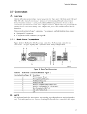
... LGA775 Processor Socket System Bus (800/533 MHz) PCI Express x16 Interface PCI Express x16 Connector Intel 82915P Memory Controller Hub (MCH) Channel A DIMM Channel B DIMM Dual-Channel Memory Bus SMBus Legacy I/O Controller LPC Bus Serial Port Parallel Port PS/2 Mouse PS/2 Keyboard Diskette Drive Connector Intel 82801FB I/O Controller Hub (ICH6) 8 Mbit Firmware Hub (FWH) Intel 915P Chipset 10/100 LAN PLC LAN Connector DMI Interconnect High Definition Audio Link LAN Connect Interface PCI Slot 1 PCI Slot 2 PCI Bus SMBus Hardware Monitoring and Fan Control ASIC Serial ATA IDE...
... LGA775 Processor Socket System Bus (800/533 MHz) PCI Express x16 Interface PCI Express x16 Connector Intel 82915P Memory Controller Hub (MCH) Channel A DIMM Channel B DIMM Dual-Channel Memory Bus SMBus Legacy I/O Controller LPC Bus Serial Port Parallel Port PS/2 Mouse PS/2 Keyboard Diskette Drive Connector Intel 82801FB I/O Controller Hub (ICH6) 8 Mbit Firmware Hub (FWH) Intel 915P Chipset 10/100 LAN PLC LAN Connector DMI Interconnect High Definition Audio Link LAN Connect Interface PCI Slot 1 PCI Slot 2 PCI Bus SMBus Hardware Monitoring and Fan Control ASIC Serial ATA IDE...
D915PDT Technical Product Specification
Page 47
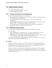
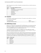
... Port B (Pink) USB ports (Yellow) [four] LAN NOTE The back panel audio line out connector is designed to the computer's chassis. The connectors can be divided into these connectors to power devices external to power headphones or amplified speakers only. Back Panel Connectors Table 15. The other internal connectors are connected to devices inside the computer's chassis, such as fans and internal peripherals. AB C E I D FG H OM17979 Figure 12. This section describes the board's connectors. Poor audio...
... Port B (Pink) USB ports (Yellow) [four] LAN NOTE The back panel audio line out connector is designed to the computer's chassis. The connectors can be divided into these connectors to power devices external to power headphones or amplified speakers only. Back Panel Connectors Table 15. The other internal connectors are connected to devices inside the computer's chassis, such as fans and internal peripherals. AB C E I D FG H OM17979 Figure 12. This section describes the board's connectors. Poor audio...

D915PDT Technical Product Specification
Page 73
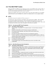
... a revision code. When the BIOS Setup configuration jumper is set to view and change the BIOS settings for the computer. The initial production BIOSs are identified as DT91510J.86A. Maintenance Main Advanced Security Power Boot Exit NOTE The maintenance menu is displayed only when the Desktop Board is poweredup, the BIOS compares the CPU version and the microcode version in configure mode. The FWH contains the BIOS Setup program, POST, the PCI autoconfiguration utility, and Plug and Play support.
... a revision code. When the BIOS Setup configuration jumper is set to view and change the BIOS settings for the computer. The initial production BIOSs are identified as DT91510J.86A. Maintenance Main Advanced Security Power Boot Exit NOTE The maintenance menu is displayed only when the Desktop Board is poweredup, the BIOS compares the CPU version and the microcode version in configure mode. The FWH contains the BIOS Setup program, POST, the PCI autoconfiguration utility, and Plug and Play support.

D915PDT Technical Product Specification
Page 74
...a PCI card, the BIOS automatically configures interrupts, the I /O channel support. PCI devices may be available for Logical Block Addressing (LBA) and 74 BIOS Setup Program Menu Bar Maintenance Main Advanced Security Clears passwords and displays processor information Displays processor and memory configuration Configures advanced features available through the chipset Sets passwords and security features Power Boot Configures power management features and power supply controls Selects boot options Exit Saves or discards changes to Setup program options Table 38 lists...
...a PCI card, the BIOS automatically configures interrupts, the I /O channel support. PCI devices may be available for Logical Block Addressing (LBA) and 74 BIOS Setup Program Menu Bar Maintenance Main Advanced Security Clears passwords and displays processor information Displays processor and memory configuration Configures advanced features available through the chipset Sets passwords and security features Power Boot Configures power management features and power supply controls Selects boot options Exit Saves or discards changes to Setup program options Table 38 lists...

D915PDT Technical Product Specification
Page 75
... operating systems. Using this information. The main component of SMBIOS is disabled. 2. When you to use SMBIOS. POST begins. 3. Overview of BIOS Features to be used to access the BIOS Setup program, and to enter and configure the BIOS Setup program and the maintenance menu. 4. For example, do not connect an ATA hard drive as third-party management software to use a USB keyboard to install an operating system that supports USB. The BIOS supports an SMBIOS table...
... operating systems. Using this information. The main component of SMBIOS is disabled. 2. When you to use SMBIOS. POST begins. 3. Overview of BIOS Features to be used to access the BIOS Setup program, and to enter and configure the BIOS Setup program and the maintenance menu. 4. For example, do not connect an ATA hard drive as third-party management software to use a USB keyboard to install an operating system that supports USB. The BIOS supports an SMBIOS table...
D915PDT Technical Product Specification
Page 78
... displays, screen repaints, or mode changes in the Drive Configuration Submenu of painting complex graphic images and changing video modes. If this condition should occur, it will not be seen. As a result, the POST does not first seek a diskette drive, which enables the system to data ready" less than eight seconds, that might be not be used. Intel Desktop Board D915PDT Technical Product Specification 3.8 Adjusting Boot Speed These factors affect system boot speed...
... displays, screen repaints, or mode changes in the Drive Configuration Submenu of painting complex graphic images and changing video modes. If this condition should occur, it will not be seen. As a result, the POST does not first seek a diskette drive, which enables the system to data ready" less than eight seconds, that might be not be used. Intel Desktop Board D915PDT Technical Product Specification 3.8 Adjusting Boot Speed These factors affect system boot speed...

D915PDT Technical Product Specification
Page 82
... enter Setup. 82 BIOS Error Messages (continued) Error Message Explanation Update OK! Memory Size Increased Memory size has increased since the last boot. NVRAM/CMOS/PASSWORD cleared by an address. KB/Interface Error Keyboard interface test failed. Off Board Parity Error A parity error occurred on an off-board card. If no memory was invalid and has been updated. This error is followed by NVRAM, CMOS, and passwords have been cleared. The system Jumper should be powered down and the jumper removed. Intel Desktop Board D915PDT...
... enter Setup. 82 BIOS Error Messages (continued) Error Message Explanation Update OK! Memory Size Increased Memory size has increased since the last boot. NVRAM/CMOS/PASSWORD cleared by an address. KB/Interface Error Keyboard interface test failed. Off Board Parity Error A parity error occurred on an off-board card. If no memory was invalid and has been updated. This error is followed by NVRAM, CMOS, and passwords have been cleared. The system Jumper should be powered down and the jumper removed. Intel Desktop Board D915PDT...
D915PDT Technical Product Specification
Page 83
... 0. Onboard KBC, RTC enabled (if present). D3 Do necessary chipset initialization, start memory refresh, and do memory sizing. Initialize interrupt vector tables, initialize system timer, initialize DMA controller and interrupt controller. This code is in the tables because that code applies to boot sector code. If either it is recovery mode or main BIOS checksum is left at port 80h. EB Booting from floppy and ATAPI device failed. Error Messages and Beep Codes 4.2 Port 80h POST Codes...
... 0. Onboard KBC, RTC enabled (if present). D3 Do necessary chipset initialization, start memory refresh, and do memory sizing. Initialize interrupt vector tables, initialize system timer, initialize DMA controller and interrupt controller. This code is in the tables because that code applies to boot sector code. If either it is recovery mode or main BIOS checksum is left at port 80h. EB Booting from floppy and ATAPI device failed. Error Messages and Beep Codes 4.2 Port 80h POST Codes...
D915PDT Technical Product Specification
Page 85
..., checking for soft reset. (If power on relocation/shadow. To enable interrupts for memory test. Pattern to clear memory below 1M memory. Amount of memory above 1M to enter in progress. Memory test started. (NOT SOFT RESET) About to adjust displayed memory size for memory wrap around test done. Going to display the first 64k memory size. Memory size display adjusted due to write patterns in F000 Shadow RAM (continued) Code 40 42 43...
..., checking for soft reset. (If power on relocation/shadow. To enable interrupts for memory test. Pattern to clear memory below 1M memory. Amount of memory above 1M to enter in progress. Memory test started. (NOT SOFT RESET) About to adjust displayed memory size for memory wrap around test done. Going to display the first 64k memory size. Memory size display adjusted due to write patterns in F000 Shadow RAM (continued) Code 40 42 43...
D915PDT Technical Product Specification
Page 88
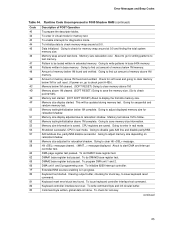
... of one short beep before passing control to initialize the video and writes the error in the upper left corner of the screen (using both monochrome and color adapters). Beep Codes Beep 1 3 6 7 8 Description CPU error Memory error System failure System failure Video error 88 The BIOS also issues a beep code (one long tone followed by a series of short tones. Intel Desktop Board D915PDT Technical Product Specification Table 47 describes the lower nibble of the high byte and indicates the bus on...
... of one short beep before passing control to initialize the video and writes the error in the upper left corner of the screen (using both monochrome and color adapters). Beep Codes Beep 1 3 6 7 8 Description CPU error Memory error System failure System failure Video error 88 The BIOS also issues a beep code (one long tone followed by a series of short tones. Intel Desktop Board D915PDT Technical Product Specification Table 47 describes the lower nibble of the high byte and indicates the bus on...
English Product Guide
Page 3
...: information about BIOS error messages and beep codes 3H B Regulatory Compliance: safety and EMC regulations, product certification 4H Conventions The following conventions are arranged as follows: 1 Desktop Board Features: a summary of data. Intended Audience The Product Guide is intended for Intel® Desktop Board D915PDT. Information Layout The chapters in this Product Guide are used in this manual: CAUTION Cautions warn the user about board layout, component installation, BIOS update, and...
...: information about BIOS error messages and beep codes 3H B Regulatory Compliance: safety and EMC regulations, product certification 4H Conventions The following conventions are arranged as follows: 1 Desktop Board Features: a summary of data. Intended Audience The Product Guide is intended for Intel® Desktop Board D915PDT. Information Layout The chapters in this Product Guide are used in this manual: CAUTION Cautions warn the user about board layout, component installation, BIOS update, and...
English Product Guide
Page 12
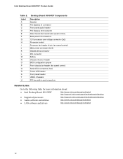
... 12 V processor core voltage connector (2x2) Processor socket Processor fan header (4-pin, fan speed control) Main power connector (2x12) Diskette drive connector IDE connector Battery Chassis intrusion header BIOS configuration jumper Front chassis fan header (fan speed control) Serial ATA connectors (four) Power LED header Front panel header USB 2.0 headers PCI bus add-in card connectors Related Links: Go to the following links for more information about: • Intel Desktop Board D915PDT http://www.intel.com/design/motherbd 16H http://support.intel.com/support/motherboards/desktop 17H...
... 12 V processor core voltage connector (2x2) Processor socket Processor fan header (4-pin, fan speed control) Main power connector (2x12) Diskette drive connector IDE connector Battery Chassis intrusion header BIOS configuration jumper Front chassis fan header (fan speed control) Serial ATA connectors (four) Power LED header Front panel header USB 2.0 headers PCI bus add-in card connectors Related Links: Go to the following links for more information about: • Intel Desktop Board D915PDT http://www.intel.com/design/motherbd 16H http://support.intel.com/support/motherboards/desktop 17H...

English Product Guide
Page 18
...-in the Firmware Hub. The BIOS is stored in cards BIOS The BIOS provides the Power-On Self-Test (POST), the BIOS Setup program, the PCI/PCI Express and IDE auto-configuration utilities, and the video BIOS. PCI and PCI Express* Auto Configuration If you install a PCI/PCI Express add-in card in your computer, the PCI/PCI Express autoconfiguration utility in card. 18 Intel Desktop Board D915PDT Product Guide Enhanced IDE Interface The ICH6's IDE interface handles the exchange of information between the processor and peripheral devices like hard disks, CD-ROM drives, and Iomega...
...-in the Firmware Hub. The BIOS is stored in cards BIOS The BIOS provides the Power-On Self-Test (POST), the BIOS Setup program, the PCI/PCI Express and IDE auto-configuration utilities, and the video BIOS. PCI and PCI Express* Auto Configuration If you install a PCI/PCI Express add-in card in your computer, the PCI/PCI Express autoconfiguration utility in card. 18 Intel Desktop Board D915PDT Product Guide Enhanced IDE Interface The ICH6's IDE interface handles the exchange of information between the processor and peripheral devices like hard disks, CD-ROM drives, and Iomega...
English Product Guide
Page 19
... for the location of the chassis 175H 176H intrusion header. If only the supervisor password is set , you must enter either password to boot the computer. The password prompt is displayed before the computer is implemented at the password prompt of the 17H 178H power connectors. 19 The security feature uses a mechanical switch on Ring ⎯ Wake from USB ⎯ Wake from PS/2 keyboard/mouse ⎯ PME# wakeup support ACPI ACPI gives...
... for the location of the chassis 175H 176H intrusion header. If only the supervisor password is set , you must enter either password to boot the computer. The password prompt is displayed before the computer is implemented at the password prompt of the 17H 178H power connectors. 19 The security feature uses a mechanical switch on Ring ⎯ Wake from USB ⎯ Wake from PS/2 keyboard/mouse ⎯ PME# wakeup support ACPI ACPI gives...
English Product Guide
Page 20
Intel Desktop Board D915PDT Product Guide Fan Connectors The desktop board has a 4-pin processor fan header and two 3-pin chassis fan headers. System fan noise may lose register settings stored in memory. It is recommended that processor fan speed control remain enabled (default BIOS setting) when using this desktop board must be able to provide enough standby current to RAM (Instantly Available PC Technology) CAUTION For Instantly Available PC technology, the 5 V standby line for the location of delivering adequate +5 V standby current. The desktop board's standby power ...
Intel Desktop Board D915PDT Product Guide Fan Connectors The desktop board has a 4-pin processor fan header and two 3-pin chassis fan headers. System fan noise may lose register settings stored in memory. It is recommended that processor fan speed control remain enabled (default BIOS setting) when using this desktop board must be able to provide enough standby current to RAM (Instantly Available PC Technology) CAUTION For Instantly Available PC technology, the 5 V standby line for the location of delivering adequate +5 V standby current. The desktop board's standby power ...

English Product Guide
Page 45
... a recovery diskette in unreliable computer operation. Table 8 shows the jumper settings for booting. 1 3 1 3 Configure (2-3) Recovery (None) After the Power-On Self-Test (POST) runs, the BIOS displays the Maintenance Menu. Moving the jumper with the power on may result in the event of the desktop board's BIOS configuration jumper block. 250H 13 OM18062 Figure 23. Jumper Settings for the BIOS Setup Program Modes Jumper Setting 1 3 Mode Normal (default) (1-2) Description The BIOS uses the current configuration and passwords for the Setup program modes. 251H...
... a recovery diskette in unreliable computer operation. Table 8 shows the jumper settings for booting. 1 3 1 3 Configure (2-3) Recovery (None) After the Power-On Self-Test (POST) runs, the BIOS displays the Maintenance Menu. Moving the jumper with the power on may result in the event of the desktop board's BIOS configuration jumper block. 250H 13 OM18062 Figure 23. Jumper Settings for the BIOS Setup Program Modes Jumper Setting 1 3 Mode Normal (default) (1-2) Description The BIOS uses the current configuration and passwords for the Setup program modes. 251H...
English Product Guide
Page 46
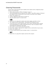
... to normal mode. 1. Setup displays the Maintenance menu. 8. Replace the cover, plug in the computer and the configuration jumper block is installed in the computer, and turn on the computer. 46 Turn off the computer. Find the configuration jumper block (see Figure 23). 254H 5. The computer starts the Setup program. Press and Setup displays a pop-up screen requesting that the board is set to boot. 7. Press to select Clear Passwords. Intel Desktop Board D915PDT Product Guide Clearing Passwords This procedure...
... to normal mode. 1. Setup displays the Maintenance menu. 8. Replace the cover, plug in the computer and the configuration jumper block is installed in the computer, and turn on the computer. 46 Turn off the computer. Find the configuration jumper block (see Figure 23). 254H 5. The computer starts the Setup program. Press and Setup displays a pop-up screen requesting that the board is set to boot. 7. Press to select Clear Passwords. Intel Desktop Board D915PDT Product Guide Clearing Passwords This procedure...

English Product Guide
Page 58
... the diskette drive. Intel Desktop Board D915PDT Product Guide BIOS Error Messages When a recoverable error occurs during the memory test. CMOS Battery Low The battery may have either been corrupted or the battery has failed. FDC Failure Error occurred trying to access hard disk controller. ATAPI Incompatible Sec Slave Drive - A: Drive Error B: Drive Error No response from corresponding drive. Replace the battery soon. HDC Failure Error occurred trying to access diskette drive controller. Check Setup to protected mode during the POST, the BIOS displays an error message...
... the diskette drive. Intel Desktop Board D915PDT Product Guide BIOS Error Messages When a recoverable error occurs during the memory test. CMOS Battery Low The battery may have either been corrupted or the battery has failed. FDC Failure Error occurred trying to access hard disk controller. ATAPI Incompatible Sec Slave Drive - A: Drive Error B: Drive Error No response from corresponding drive. Replace the battery soon. HDC Failure Error occurred trying to access diskette drive controller. Check Setup to protected mode during the POST, the BIOS displays an error message...
Simplified Chinese Product Guide
Page 10
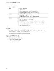
D915PDT 表 1 BIOS AMI BIOS • 支持 SMBIOS • Intel® Rapid BIOS Boot BIOS 启动) • Intel® Express BIOS Update BIOS 更新) 电源管理 ACPI RAM (STR) • USB、PCI、PCI Express、PS/2、LAN 硬件管理 • Intel® Precision Cooling Technology D915PDT TPS)、BIOS http://support.intel.com/support/motherboards/desktop/ Microsoft Windows* 2000 • Microsoft Windows XP 10
D915PDT 表 1 BIOS AMI BIOS • 支持 SMBIOS • Intel® Rapid BIOS Boot BIOS 启动) • Intel® Express BIOS Update BIOS 更新) 电源管理 ACPI RAM (STR) • USB、PCI、PCI Express、PS/2、LAN 硬件管理 • Intel® Precision Cooling Technology D915PDT TPS)、BIOS http://support.intel.com/support/motherboards/desktop/ Microsoft Windows* 2000 • Microsoft Windows XP 10


