
Product Specification
Page 2
... any time, without notice. Date September 2004 October 2004 This product specification applies to deviate from published specifications. Intel® desktop boards may cause the product to only standard Intel® Desktop Board D915GVWB with BIOS identifier WB91X10J.86A. Current characterized errata are registered trademarks of documents which may contain design defects or errors...
... any time, without notice. Date September 2004 October 2004 This product specification applies to deviate from published specifications. Intel® desktop boards may cause the product to only standard Intel® Desktop Board D915GVWB with BIOS identifier WB91X10J.86A. Current characterized errata are registered trademarks of documents which may contain design defects or errors...
Product Specification
Page 3
... not intended for the Intel® Desktop Board D915GVWB. CAUTION Cautions are used to call attention to important information. # INTEGRATOR'S NOTES Integrator's notes are included to provide detailed, technical information about the conventions used on the Desktop Board D915GVWB A map of the... resources of the Desktop Board The features supported by the BIOS Setup program A description of this specification. WARNING Warnings indicate conditions, which if not ...
... not intended for the Intel® Desktop Board D915GVWB. CAUTION Cautions are used to call attention to important information. # INTEGRATOR'S NOTES Integrator's notes are included to provide detailed, technical information about the conventions used on the Desktop Board D915GVWB A map of the... resources of the Desktop Board The features supported by the BIOS Setup program A description of this specification. WARNING Warnings indicate conditions, which if not ...
Product Specification
Page 6
Intel Desktop Board D915GVWB Technical Product Specification 2.3 DMA Channels ...41 2.4 Fixed I/O Map...42 2.5 PCI Configuration Space Map 43 2.6 Interrupts ...44 2.7 PCI Conventional Interrupt Routing Map 45 2.8 Connectors...46 2.8.1 Back ... ...73 3.7.1 CD-ROM Boot 73 3.7.2 Network Boot 73 3.7.3 Booting Without Attached Devices 73 3.7.4 Changing the Default Boot Device During POST 73 3.8 Fast Booting Systems with Intel® Rapid BIOS Boot 74 3.8.1 Peripheral Selection and Configuration 74 3.8.2 Intel Rapid BIOS Boot 74 3.9 BIOS Security Features 75 vi
Intel Desktop Board D915GVWB Technical Product Specification 2.3 DMA Channels ...41 2.4 Fixed I/O Map...42 2.5 PCI Configuration Space Map 43 2.6 Interrupts ...44 2.7 PCI Conventional Interrupt Routing Map 45 2.8 Connectors...46 2.8.1 Back ... ...73 3.7.1 CD-ROM Boot 73 3.7.2 Network Boot 73 3.7.3 Booting Without Attached Devices 73 3.7.4 Changing the Default Boot Device During POST 73 3.8 Fast Booting Systems with Intel® Rapid BIOS Boot 74 3.8.1 Peripheral Selection and Configuration 74 3.8.2 Intel Rapid BIOS Boot 74 3.9 BIOS Security Features 75 vi
Product Specification
Page 7
.... Block Diagram...14 3. Supported System Bus Frequency and Memory Speed Combinations 16 5. Contents 4 Error Messages and Beep Codes 4.1 BIOS Error Messages 77 4.2 Port 80h POST Codes 79 4.3 Bus Initialization Checkpoints 83 4.4 Speaker ...84 4.5 BIOS Beep Codes...84 Figures 1. Board Components ...12 2. Single Channel (Asymmetric) Mode Configuration with One DIMM 20 8. Back Panel...
.... Block Diagram...14 3. Supported System Bus Frequency and Memory Speed Combinations 16 5. Contents 4 Error Messages and Beep Codes 4.1 BIOS Error Messages 77 4.2 Port 80h POST Codes 79 4.3 Bus Initialization Checkpoints 83 4.4 Speaker ...84 4.5 BIOS Beep Codes...84 Figures 1. Board Components ...12 2. Single Channel (Asymmetric) Mode Configuration with One DIMM 20 8. Back Panel...
Product Specification
Page 8
...62 33. Safety Regulations ...64 35. Product Certification Markings 67 37. BIOS Setup Program Menu Bar 70 38. Boot Block Recovery Code Checkpoints 79 44. Lower Nibble High Byte Functions 84 48. Intel Desktop Board D915GVWB Technical Product Specification 14. Chassis Intrusion Connector 50 22. Serial ATA Connectors...RAM 80 45. States for a Two-Color Power LED 53 29. EMC Regulations ...64 36. Upper Nibble High Byte Functions 83 47. BIOS Error Messages 77 42. Front Chassis Fan and Rear Chassis Fan Connectors 50 20. Interrupts ...44 15. Supervisor and User Password Functions 75...
...62 33. Safety Regulations ...64 35. Product Certification Markings 67 37. BIOS Setup Program Menu Bar 70 38. Boot Block Recovery Code Checkpoints 79 44. Lower Nibble High Byte Functions 84 48. Intel Desktop Board D915GVWB Technical Product Specification 14. Chassis Intrusion Connector 50 22. Serial ATA Connectors...RAM 80 45. States for a Two-Color Power LED 53 29. EMC Regulations ...64 36. Upper Nibble High Byte Functions 83 47. BIOS Error Messages 77 42. Front Chassis Fan and Rear Chassis Fan Connectors 50 20. Interrupts ...44 15. Supervisor and User Password Functions 75...
Product Specification
Page 10
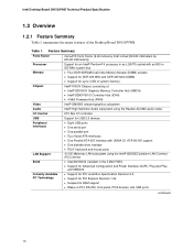
...GB of system memory Intel® 915GV Chipset, consisting of the Desktop Board D915GVWB. Table 1. Intel Desktop Board D915GVWB Technical Product Specification 1.2 Overview 1.2.1 Feature Summary Table 1 summarizes the major features of : • Intel® 82915GV Graphics Memory Controller Hub (GMCH) • Intel® 82801FB I/O ...interface • PS/2* keyboard and mouse ports 10/100 Mbits/sec LAN subsystem using the Intel® 82562EZ platform LAN Connect (PLC) device • Intel/AMI BIOS (resident in the 4 Mbit FWH) • Support for Advanced Configuration and Power Interface...
...GB of system memory Intel® 915GV Chipset, consisting of the Desktop Board D915GVWB. Table 1. Intel Desktop Board D915GVWB Technical Product Specification 1.2 Overview 1.2.1 Feature Summary Table 1 summarizes the major features of : • Intel® 82915GV Graphics Memory Controller Hub (GMCH) • Intel® 82801FB I/O ...interface • PS/2* keyboard and mouse ports 10/100 Mbits/sec LAN subsystem using the Intel® 82562EZ platform LAN Connect (PLC) device • Intel/AMI BIOS (resident in the 4 Mbit FWH) • Support for Advanced Configuration and Power Interface...

Product Specification
Page 13
...connectors +12V power connector (ATX12V) LGA775 processor socket Hardware monitoring and fan control ASIC Processor fan connector Intel 82915GV GMCH DIMM Channel A sockets DIMM Channel B sockets I/O controller Power connector Diskette drive connector Parallel ATE IDE connector Battery... Chassis intrusion connector BIOS Setup configuration jumper block 4 Mbit Firmware Hub (FWH) Front chassis fan connector Serial ATA connectors (4) Auxiliary front panel power LED connector Front panel connector Front panel USB connectors Intel 82801FB I/O Controller Hub (ICH6) Front...
...connectors +12V power connector (ATX12V) LGA775 processor socket Hardware monitoring and fan control ASIC Processor fan connector Intel 82915GV GMCH DIMM Channel A sockets DIMM Channel B sockets I/O controller Power connector Diskette drive connector Parallel ATE IDE connector Battery... Chassis intrusion connector BIOS Setup configuration jumper block 4 Mbit Firmware Hub (FWH) Front chassis fan connector Serial ATA connectors (4) Auxiliary front panel power LED connector Front panel connector Front panel USB connectors Intel 82801FB I/O Controller Hub (ICH6) Front...

Product Specification
Page 16
...is available. Table 4. Supported System Bus Frequency and Memory Speed Combinations To use this type of address space is installed, the BIOS will attempt to Section 2.2.1, on page 39 for additional information on available memory. 16 This minimizes system latencies to accurately configure ... configure the memory settings, but performance and reliability may be impacted or the DIMMs may not function under the determined frequency. Intel Desktop Board D915GVWB Technical Product Specification • Non-ECC DIMMs • Serial Presence Detect • DDR 400 MHz and DDR 333 MHz ...
...is available. Table 4. Supported System Bus Frequency and Memory Speed Combinations To use this type of address space is installed, the BIOS will attempt to Section 2.2.1, on page 39 for additional information on available memory. 16 This minimizes system latencies to accurately configure ... configure the memory settings, but performance and reliability may be impacted or the DIMMs may not function under the determined frequency. Intel Desktop Board D915GVWB Technical Product Specification • Non-ECC DIMMs • Serial Presence Detect • DDR 400 MHz and DDR 333 MHz ...
Product Specification
Page 21
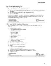
... to http://developer.intel.com/ Chapter 2 1.6.1 Intel 915GV Graphics Subsystem The Intel GMA900 graphics controller (contained within the 82915GV GMCH) features the following devices: • Intel 82915GV Graphics Memory Controller Hub (GMCH) with Direct Media Interface (DMI) interconnect • Intel 82801FB I /O ...controller for software MPEG2 decode • Dynamic Video Memory Technology (DVMT) support up to 224 MB • Intel® Zoom Utility For information about DVMT Obtaining graphics software and utilities Refer to Section 1.6.1.1, page 22 Section 1.3, page 15...
... to http://developer.intel.com/ Chapter 2 1.6.1 Intel 915GV Graphics Subsystem The Intel GMA900 graphics controller (contained within the 82915GV GMCH) features the following devices: • Intel 82915GV Graphics Memory Controller Hub (GMCH) with Direct Media Interface (DMI) interconnect • Intel 82801FB I /O ...controller for software MPEG2 decode • Dynamic Video Memory Technology (DVMT) support up to 224 MB • Intel® Zoom Utility For information about DVMT Obtaining graphics software and utilities Refer to Section 1.6.1.1, page 22 Section 1.3, page 15...
Product Specification
Page 22
...use a minimal fixed portion of system memory is as follows: • Four ports are routed to the graphics buffer as set in the BIOS Setup program) for maximum 2-D/3-D graphics performance. DVMT returns system memory back to eight USB 2.0 ports, supports UHCI and EHCI, and uses ...DVMT when less than 512 MB of system memory can be allocated to Figure 15, page 46 Figure 16, page 48 22 Intel Desktop Board D915GVWB Technical Product Specification 1.6.1.1 Dynamic Video Memory Technology (DVMT) DVMT enables enhanced graphics and memory performance through Direct AGP, and highly ...
...use a minimal fixed portion of system memory is as follows: • Four ports are routed to the graphics buffer as set in the BIOS Setup program) for maximum 2-D/3-D graphics performance. DVMT returns system memory back to eight USB 2.0 ports, supports UHCI and EHCI, and uses ...DVMT when less than 512 MB of system memory can be allocated to Figure 15, page 46 Figure 16, page 48 22 Intel Desktop Board D915GVWB Technical Product Specification 1.6.1.1 Dynamic Video Memory Technology (DVMT) DVMT enables enhanced graphics and memory performance through Direct AGP, and highly ...

Product Specification
Page 23
... ATA IDE interface also supports ATAPI devices (such as a boot device by setting the BIOS Setup program's Boot menu to device connections, unlike Parallel ATA IDE which supports a master...NOTE ATA-66 and ATA-100 are faster timings and require a specialized cable to the BIOS. The ICH6's ATA-100 logic can be configured as CD-ROM drives) and ATA devices using the transfer modes.... The BIOS supports Logical Block Addressing (LBA) and Extended Cylinder Head Sector (ECHS) translation modes. The board ...
... ATA IDE interface also supports ATAPI devices (such as a boot device by setting the BIOS Setup program's Boot menu to device connections, unlike Parallel ATA IDE which supports a master...NOTE ATA-66 and ATA-100 are faster timings and require a specialized cable to the BIOS. The ICH6's ATA-100 logic can be configured as CD-ROM drives) and ATA devices using the transfer modes.... The BIOS supports Logical Block Addressing (LBA) and Extended Cylinder Head Sector (ECHS) translation modes. The board ...

Product Specification
Page 25
...15, page 46 1.8.3 Diskette Drive Controller The I /O controller. 1.8.1 Serial Port The Desktop Board provides one diskette drive. Use the BIOS Setup program to set the parallel port mode. Product Description 1.8 I/O Controller The I/O controller provides the following features: • One ... • Intelligent power management, including a programmable wake-up event interface • PCI Conventional bus power management support The BIOS Setup program provides configuration options for the I /O controller supports one serial port, located on the back panel. For information...
...15, page 46 1.8.3 Diskette Drive Controller The I /O controller. 1.8.1 Serial Port The Desktop Board provides one diskette drive. Use the BIOS Setup program to set the parallel port mode. Product Description 1.8 I/O Controller The I/O controller provides the following features: • One ... • Intelligent power management, including a programmable wake-up event interface • PCI Conventional bus power management support The BIOS Setup program provides configuration options for the I /O controller supports one serial port, located on the back panel. For information...
Product Specification
Page 29
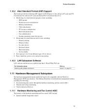
...• Reset, shutdown, power cycle, and power up options 1.10.3 LAN Subsystem Software LAN software and drivers are available from Intel's World Wide Web site. Product Description 1.10.2 Alert Standard Format (ASF) Support The boards provide the following : • Fan... bus add-in LAN cards installed in PCI Conventional bus slot 2: • Monitoring of system firmware progress events, including: ⎯ BIOS present ⎯ Primary processor initialization ⎯ Memory initialization ⎯ Video initialization ⎯ PCI resource configuration ⎯ Hard-disk initialization ...
...• Reset, shutdown, power cycle, and power up options 1.10.3 LAN Subsystem Software LAN software and drivers are available from Intel's World Wide Web site. Product Description 1.10.2 Alert Standard Format (ASF) Support The boards provide the following : • Fan... bus add-in LAN cards installed in PCI Conventional bus slot 2: • Monitoring of system firmware progress events, including: ⎯ BIOS present ⎯ Primary processor initialization ⎯ Memory initialization ⎯ Video initialization ⎯ PCI resource configuration ⎯ Hard-disk initialization ...
Product Specification
Page 31
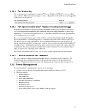
... the processor fan speed control will vary based on the chassis that processor fan speed control remain enabled (default BIOS setting) when using Intel® Desktop Utilities, LANDesk* software, or thirdparty software. Disabling the chassis fan speed control results in the ...functions of monitoring and control is recommended that attaches to Section 1.12.2.2, page 35 1.11.4 Fan Speed Control (Intel® Precision Cooling Technology) Intel® Precision Cooling Technology automatically adjusts the processor fan speed based on the processor thermal diode temperature and adjusts the...
... the processor fan speed control will vary based on the chassis that processor fan speed control remain enabled (default BIOS setting) when using Intel® Desktop Utilities, LANDesk* software, or thirdparty software. Disabling the chassis fan speed control results in the ...functions of monitoring and control is recommended that attaches to Section 1.12.2.2, page 35 1.11.4 Fan Speed Control (Intel® Precision Cooling Technology) Intel® Precision Cooling Technology automatically adjusts the processor fan speed based on the processor thermal diode temperature and adjusts the...
Product Specification
Page 33
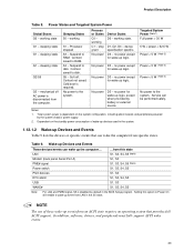
... power D1, D2, D3 - sleeping state S4 - no power except for wake-up logic. mechanical off . Dependent on the system configuration, including add-in the BIOS Setup program. Wake-up Devices and Events These devices/events can be performed safely. Product Description Table 8. working state. No power D3 - Cold boot is...
... power D1, D2, D3 - sleeping state S4 - no power except for wake-up logic. mechanical off . Dependent on the system configuration, including add-in the BIOS Setup program. Wake-up Devices and Events These devices/events can be performed safely. Product Description Table 8. working state. No power D3 - Cold boot is...
Product Specification
Page 34
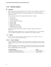
Intel Desktop Board D915GVWB Technical Product Specification 1.12.2 Hardware Support CAUTION Ensure that provides full ACPI support. 1.12.2.1 Power Connector ATX12V-compliant power supplies can turn off ). The board ... options. The total amount of telephony device (external or internal). When resuming from the +5 V standby line. Failure to the power state it is in the BIOS Setup program's Boot menu.
Intel Desktop Board D915GVWB Technical Product Specification 1.12.2 Hardware Support CAUTION Ensure that provides full ACPI support. 1.12.2.1 Power Connector ATX12V-compliant power supplies can turn off ). The board ... options. The total amount of telephony device (external or internal). When resuming from the +5 V standby line. Failure to the power state it is in the BIOS Setup program's Boot menu.

Product Specification
Page 36
... Wake from USB requires the use of Instantly Available PC technology requires operating system support and PCI 2.2 compliant add-in cards, PCI Express add-in BIOS). 1.12.2.9 WAKE# Signal Wake-up Support When the PME# signal on the PCI Conventional bus is asserted, the computer wakes from an ACPI S1, S3... shows the location of Resume on the PCI Express bus is still lit, disconnect the power cord before installing or removing any attached devices. 36 Intel Desktop Board D915GVWB Technical Product Specification The board supports the PCI Bus Power Management Interface Specification.
... Wake from USB requires the use of Instantly Available PC technology requires operating system support and PCI 2.2 compliant add-in cards, PCI Express add-in BIOS). 1.12.2.9 WAKE# Signal Wake-up Support When the PME# signal on the PCI Conventional bus is asserted, the computer wakes from an ACPI S1, S3... shows the location of Resume on the PCI Express bus is still lit, disconnect the power cord before installing or removing any attached devices. 36 Intel Desktop Board D915GVWB Technical Product Specification The board supports the PCI Bus Power Management Interface Specification.

Product Specification
Page 39
......41 2.4 Fixed I /O map, Table 13 defines the PCI Conventional bus configuration space map, and Table 14 describes the interrupts. These functions include the following: • BIOS/firmware hub (2 MB) • Local APIC (19 MB) • Digital Media Interface (40 MB) • Front side bus interrupts (17 MB) • PCI.... 2.2 Memory Resources 2.2.1 Addressable Memory The board utilizes 4 GB of DRAM (total system memory). The remaining sections in cards, PCI Express configuration space, BIOS (firmware hub), and chipset overhead resides above the top of addressable system memory.
......41 2.4 Fixed I /O map, Table 13 defines the PCI Conventional bus configuration space map, and Table 14 describes the interrupts. These functions include the following: • BIOS/firmware hub (2 MB) • Local APIC (19 MB) • Digital Media Interface (40 MB) • Front side bus interrupts (17 MB) • PCI.... 2.2 Memory Resources 2.2.1 Addressable Memory The board utilizes 4 GB of DRAM (total system memory). The remaining sections in cards, PCI Express configuration space, BIOS (firmware hub), and chipset overhead resides above the top of addressable system memory.

Product Specification
Page 40
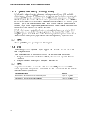
... based on add-in Card BIOS and Buffer area (128 KB; 16 KB x 8) Standard PCI/ ISA Video Memory (SMM Memory) 128 KB DOS area (640 KB) 1 MB 960 KB 896 KB 768 KB 640 KB 0 KB OM17140 Figure 14. Detailed System Memory Address Map 40 Intel Desktop Board D915GVWB Technical Product Specification The... a schematic of usable DRAM (memory visible to the operating system) 1 MB 640 KB 0 MB 0FFFFFH 0F0000H 0EFFFFH 0E0000H 0DFFFFH 0C0000H 0BFFFFH 0A0000H 09FFFFH 00000H Upper BIOS area (64 KB) Lower BIOS area (64 KB; 16 KB x 4) Add-in cards and...
... based on add-in Card BIOS and Buffer area (128 KB; 16 KB x 8) Standard PCI/ ISA Video Memory (SMM Memory) 128 KB DOS area (640 KB) 1 MB 960 KB 896 KB 768 KB 640 KB 0 KB OM17140 Figure 14. Detailed System Memory Address Map 40 Intel Desktop Board D915GVWB Technical Product Specification The... a schematic of usable DRAM (memory visible to the operating system) 1 MB 640 KB 0 MB 0FFFFFH 0F0000H 0EFFFFH 0E0000H 0DFFFFH 0C0000H 0BFFFFH 0A0000H 09FFFFH 00000H Upper BIOS area (64 KB) Lower BIOS area (64 KB; 16 KB x 4) Add-in cards and...
Product Specification
Page 41
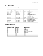
... port Diskette drive Parallel port (for ECP or EPP) DMA controller Open Open Open 41 EFFFF C8000 - Dependent on video adapter used. Video memory and BIOS Extended BIOS data (movable by memory manager software) Extended conventional memory Conventional memory 2.3 DMA Channels Table 11. Technical Reference 2.2.2 Memory Map Table 10 lists the system... - 9FFFF 80000 - 9FBFF 00000 - 7FFFF Size 4095 MB 64 KB 64 KB 96 KB 160 KB 1 KB 127 KB 512 KB Description Extended memory Runtime BIOS Reserved Potential available high DOS memory (open to the PCI Conventional bus).
... port Diskette drive Parallel port (for ECP or EPP) DMA controller Open Open Open 41 EFFFF C8000 - Dependent on video adapter used. Video memory and BIOS Extended BIOS data (movable by memory manager software) Extended conventional memory Conventional memory 2.3 DMA Channels Table 11. Technical Reference 2.2.2 Memory Map Table 10 lists the system... - 9FFFF 80000 - 9FBFF 00000 - 7FFFF Size 4095 MB 64 KB 64 KB 96 KB 160 KB 1 KB 127 KB 512 KB Description Extended memory Runtime BIOS Reserved Potential available high DOS memory (open to the PCI Conventional bus).


