User Manual
Page 6
Intel Desktop Board D915GEV/D915GUX/D915GAV/D915GAG Product Guide Installing and Removing the Desktop Board 31 Installing and Removing a Processor 32 Installing a Processor 32 Installing the Processor Fan Heat Sink 34 Connecting the Processor Fan Heat Sink Cable 35... Connecting the IDE Cable...42 Connecting the Serial ATA (SATA) Cable 43 Connecting Internal Headers 44 Installing a Front Panel Audio Solution 45 Connecting USB 2.0 Headers 46 Connecting the Front Panel Header 46 Setting Up the Flexible 6-Channel Audio with Jack Re-tasking 47 Connecting Fan and Power Cables 48 Connecting...
Intel Desktop Board D915GEV/D915GUX/D915GAV/D915GAG Product Guide Installing and Removing the Desktop Board 31 Installing and Removing a Processor 32 Installing a Processor 32 Installing the Processor Fan Heat Sink 34 Connecting the Processor Fan Heat Sink Cable 35... Connecting the IDE Cable...42 Connecting the Serial ATA (SATA) Cable 43 Connecting Internal Headers 44 Installing a Front Panel Audio Solution 45 Connecting USB 2.0 Headers 46 Connecting the Front Panel Header 46 Setting Up the Flexible 6-Channel Audio with Jack Re-tasking 47 Connecting Fan and Power Cables 48 Connecting...
User Manual
Page 7
Intel Desktop Boards D915GUX and D915GAG Components 14 3. Dual Configuration Example 3 37 17. Connecting 2x12 Power Supply Cables 50 27. Location of the PCI Bus and PCI Express Add-in Card, and Peripheral Interface Connectors for Flexible 6-Channel Audio System 47 24. Desktop Boards D915GAV and D915GEV Components 12 2. Back Panel LAN Connector LED Locations 20 4. Desktop Boards D915GEV...Lever...32 8. Connecting the Serial ATA Cable 43 22. Back Panel Audio Connectors for Desktop Boards D915GAV and D915GEV 51 28. Location of Standby Power Indicator 25 5. Location of...
Intel Desktop Boards D915GUX and D915GAG Components 14 3. Dual Configuration Example 3 37 17. Connecting 2x12 Power Supply Cables 50 27. Location of the PCI Bus and PCI Express Add-in Card, and Peripheral Interface Connectors for Flexible 6-Channel Audio System 47 24. Desktop Boards D915GAV and D915GEV Components 12 2. Back Panel LAN Connector LED Locations 20 4. Desktop Boards D915GEV...Lever...32 8. Connecting the Serial ATA Cable 43 22. Back Panel Audio Connectors for Desktop Boards D915GAV and D915GEV 51 28. Location of Standby Power Indicator 25 5. Location of...
User Manual
Page 8
...Memory Map...71 14. EMC Regulations...79 20. Product Certification Markings 80 viii Desktop Board D915GEV/D915GUX Memory Configurations 18 7. USB 2.0 Header Signal Names 46 11. DMA...Desktop Board D915GAV/D915GAG Memory Configurations 17 6. Interrupts ...72 16. Desktop Boards D915GAG and D915GUX Components 15 5. Safety Regulations ...77 19. RJ-45 10/100 Ethernet LAN Connector LEDs 21 8. Manufacturing Options 11 3. Front Panel Header Signal Names 46 12. Intel Desktop Board D915GEV/D915GUX/D915GAV/D915GAG Product Guide Tables 1. Desktop Boards D915GAV and D915GEV...
...Memory Map...71 14. EMC Regulations...79 20. Product Certification Markings 80 viii Desktop Board D915GEV/D915GUX Memory Configurations 18 7. USB 2.0 Header Signal Names 46 11. DMA...Desktop Board D915GAV/D915GAG Memory Configurations 17 6. Interrupts ...72 16. Desktop Boards D915GAG and D915GUX Components 15 5. Safety Regulations ...77 19. RJ-45 10/100 Ethernet LAN Connector LEDs 21 8. Manufacturing Options 11 3. Front Panel Header Signal Names 46 12. Intel Desktop Board D915GEV/D915GUX/D915GAV/D915GAG Product Guide Tables 1. Desktop Boards D915GAV and D915GEV...
User Manual
Page 10
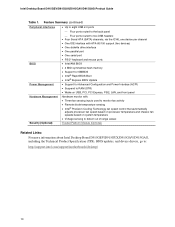
... (continued) Peripheral Interfaces • Up to eight USB 2.0 ports ⎯ Four ports routed to the back panel ⎯ Four ports routed to two USB headers • Four Serial ATA (SATA) channels, via the ICH6... Security (Optional) Trusted Platform Module (Optional) Related Links: For more information about Intel Desktop Board D915GEV/D915GUX/D915GAV/D915GAG, including the Technical Product Specification (TPS), BIOS updates, and device drivers, go to: http://support.intel.com/support/motherboards/desktop/ 10 Intel Desktop Board D915GEV/D915GUX/D915GAV/D915GAG Product Guide Table 1.
... (continued) Peripheral Interfaces • Up to eight USB 2.0 ports ⎯ Four ports routed to the back panel ⎯ Four ports routed to two USB headers • Four Serial ATA (SATA) channels, via the ICH6... Security (Optional) Trusted Platform Module (Optional) Related Links: For more information about Intel Desktop Board D915GEV/D915GUX/D915GAV/D915GAG, including the Technical Product Specification (TPS), BIOS updates, and device drivers, go to: http://support.intel.com/support/motherboards/desktop/ 10 Intel Desktop Board D915GEV/D915GUX/D915GAV/D915GAG Product Guide Table 1.
User Manual
Page 13
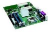
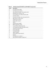
Label A B C D E F G H I J K L M N O P Q R S T U V W Desktop Boards D915GAV and D915GEV Components Description Front panel audio header PCI Express x16 connector Rear chassis fan header 1 (fan speed control) Alternate power connector (1x4) 12 V processor core voltage connector... jumper Trusted Platform Module (optional) Front chassis fan header (fan speed control) Serial ATA connectors (four) Power LED header Front panel header USB 2.0 headers PCI bus add-in card connectors Speaker PCI Express x1 connectors Rear chassis fan header 2 (always on) 13 Desktop Board Features Table 3.
Label A B C D E F G H I J K L M N O P Q R S T U V W Desktop Boards D915GAV and D915GEV Components Description Front panel audio header PCI Express x16 connector Rear chassis fan header 1 (fan speed control) Alternate power connector (1x4) 12 V processor core voltage connector... jumper Trusted Platform Module (optional) Front chassis fan header (fan speed control) Serial ATA connectors (four) Power LED header Front panel header USB 2.0 headers PCI bus add-in card connectors Speaker PCI Express x1 connectors Rear chassis fan header 2 (always on) 13 Desktop Board Features Table 3.
User Manual
Page 15
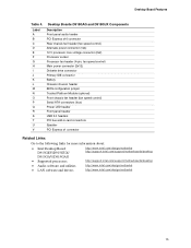
... LED header Front panel header USB 2.0 headers PCI bus add-in card connectors Speaker PCI Express x1 connector Related Links: Go to the following links for more information about: • Intel Desktop Board D915GEV/D915GUX/ D915GAV/D915GAG • Supported processors http://www.intel.com/design/motherbd http://support.intel.com/support/motherboards/desktop http://support.intel.com/support/motherboards/desktop • Audio...
... LED header Front panel header USB 2.0 headers PCI bus add-in card connectors Speaker PCI Express x1 connector Related Links: Go to the following links for more information about: • Intel Desktop Board D915GEV/D915GUX/ D915GAV/D915GAG • Supported processors http://www.intel.com/design/motherbd http://support.intel.com/support/motherboards/desktop http://support.intel.com/support/motherboards/desktop • Audio...
User Manual
Page 19
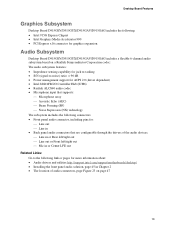
Desktop Board Features Graphics Subsystem Desktop Board D915GEV/D915GUX/D915GAV/D915GAG includes the following: • Intel 915G Express Chipset • Intel Graphics Media Accelerator 900 • PCI Express x16 connector for graphics expansion Audio Subsystem Desktop Board D915GEV/D915GUX/D915GAV/D915GAG includes a flexible 6-channel audio ...link or pages for more information about: • Audio drivers and utilities http://support.intel.com/support/motherboards/desktop/ • Installing the front panel audio solution, page 45 in Chapter 2 • The location of audio connectors, ...
Desktop Board Features Graphics Subsystem Desktop Board D915GEV/D915GUX/D915GAV/D915GAG includes the following: • Intel 915G Express Chipset • Intel Graphics Media Accelerator 900 • PCI Express x16 connector for graphics expansion Audio Subsystem Desktop Board D915GEV/D915GUX/D915GAV/D915GAG includes a flexible 6-channel audio ...link or pages for more information about: • Audio drivers and utilities http://support.intel.com/support/motherboards/desktop/ • Installing the front panel audio solution, page 45 in Chapter 2 • The location of audio connectors, ...
User Manual
Page 20
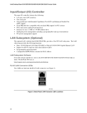
... PS/2-style mouse and keyboard interfaces • Interface for RJ-45 connector with the Intel 82801FB (ICH6), provides a Fast PCI LAN subsystem. Back Panel LAN Connector LED Locations 20 Intel Desktop Board D915GEV/D915GUX/D915GAV/D915GAG Product Guide Input/Output (I/O) Controller The super I/O controller features the following... MAC address LAN Subsystem Software For LAN software and drivers, refer to the D915GEV/D915GUX/D915GAV/D915GAG link on Intel's World Wide Web site at: http://support.intel.com/support/motherboards/desktop RJ-45 LAN Connector LEDs Two LEDs are built into the RJ-45 LAN...
... PS/2-style mouse and keyboard interfaces • Interface for RJ-45 connector with the Intel 82801FB (ICH6), provides a Fast PCI LAN subsystem. Back Panel LAN Connector LED Locations 20 Intel Desktop Board D915GEV/D915GUX/D915GAV/D915GAG Product Guide Input/Output (I/O) Controller The super I/O controller features the following... MAC address LAN Subsystem Software For LAN software and drivers, refer to the D915GEV/D915GUX/D915GAV/D915GAG link on Intel's World Wide Web site at: http://support.intel.com/support/motherboards/desktop RJ-45 LAN Connector LEDs Two LEDs are built into the RJ-45 LAN...

User Manual
Page 21
Table 8 describes the LED states when the board is powered up to eight USB 2.0 ports via ICH6; LAN link is not established. USB 1.1 devices will ... 2.0 ports to two internal USB 2.0 headers. The desktop board supports up and the 10/100/1000 Gigabit Ethernet LAN subsystem is communicating with USB 1.1 devices. Desktop Board Features Table 7 describes the LED states when the board is powered up and the 10/100 Ethernet LAN subsystem... if no device or a low-speed USB device is selected. Table 7. four ports routed to the back panel and four routed to USB 1.1 operation.
Table 8 describes the LED states when the board is powered up to eight USB 2.0 ports via ICH6; LAN link is not established. USB 1.1 devices will ... 2.0 ports to two internal USB 2.0 headers. The desktop board supports up and the 10/100/1000 Gigabit Ethernet LAN subsystem is communicating with USB 1.1 devices. Desktop Board Features Table 7 describes the LED states when the board is powered up and the 10/100 Ethernet LAN subsystem... if no device or a low-speed USB device is selected. Table 7. four ports routed to the back panel and four routed to USB 1.1 operation.
User Manual
Page 25
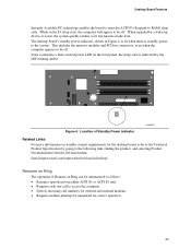
... front panel, the sleep state is standby power to access the computer • Detects incoming call to the system. This includes the memory modules and PCI bus connectors, even when the computer appears to -RAM) sleep state. Desktop Board Features... Instantly Available PC technology enables the board to enter the ACPI S3 (Suspend-to be off . While in Figure 4, is lit when there is indicated by going to the following link, finding the product, and selecting Product Documentation from the left-hand menu: http://support.intel.com/support/motherboards/desktop...
... front panel, the sleep state is standby power to access the computer • Detects incoming call to the system. This includes the memory modules and PCI bus connectors, even when the computer appears to -RAM) sleep state. Desktop Board Features... Instantly Available PC technology enables the board to enter the ACPI S3 (Suspend-to be off . While in Figure 4, is lit when there is indicated by going to the following link, finding the product, and selecting Product Documentation from the left-hand menu: http://support.intel.com/support/motherboards/desktop...
User Manual
Page 27
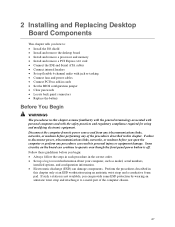
...8226; Clear passwords • Locate back panel connectors • Replace the battery Before You Begin WARNINGS The procedures in this chapter only at an ESD workstation using and modifying electronic equipment. 2 Installing and Replacing Desktop Board Components This chapter tells you how to...: • Install the I/O shield • Install and remove the desktop board • Install and remove a processor and memory • Install and...
...8226; Clear passwords • Locate back panel connectors • Replace the battery Before You Begin WARNINGS The procedures in this chapter only at an ESD workstation using and modifying electronic equipment. 2 Installing and Replacing Desktop Board Components This chapter tells you how to...: • Install the I/O shield • Install and remove the desktop board • Install and remove a processor and memory • Install and...
User Manual
Page 41
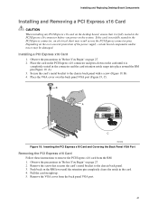
...19, A). 3. Installing and Replacing Desktop Board Components Installing and Removing a PCI Express x16 Card CAUTION When installing any PCI Express x16 card on the desktop board, ensure that secures the card's metal bracket to remove the PCI Express x16 card from the back panel VGA port. 41 Secure the card...'s metal bracket to the chassis back panel with a screw (Figure 19, B). 4. Remove ...
...19, A). 3. Installing and Replacing Desktop Board Components Installing and Removing a PCI Express x16 Card CAUTION When installing any PCI Express x16 card on the desktop board, ensure that secures the card's metal bracket to remove the PCI Express x16 card from the back panel VGA port. 41 Secure the card...'s metal bracket to the chassis back panel with a screw (Figure 19, B). 4. Remove ...
User Manual
Page 44
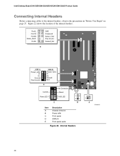
... On/Off 87 65 Reset Power LED 43 HD LED 3 21 1 C B Item A B C D E Description Chassis intrusion Power LED Front panel USB 2.0 Front panel audio Figure 22. Figure 22 shows the location of the internal headers. Intel Desktop Board D915GEV/D915GUX/D915GAV/D915GAG Product Guide Connecting Internal Headers Before connecting cables to the internal headers, observe the precautions...
... On/Off 87 65 Reset Power LED 43 HD LED 3 21 1 C B Item A B C D E Description Chassis intrusion Power LED Front panel USB 2.0 Front panel audio Figure 22. Figure 22 shows the location of the internal headers. Intel Desktop Board D915GEV/D915GUX/D915GAV/D915GAG Product Guide Connecting Internal Headers Before connecting cables to the internal headers, observe the precautions...
User Manual
Page 45
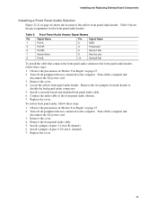
... cover. 4. Connect the audio cable to disable the back panel audio connectors. 5. Observe the precautions in "Before You Begin" on pins 5-6 (rear R channel). 6. Locate the yellow front panel audio header. To restore back panel audio, follow these steps: 1. Installing and Replacing Desktop Board Components Installing a Front Panel Audio Solution Figure 22, E on pins 9-10 (rear L channel...
... cover. 4. Connect the audio cable to disable the back panel audio connectors. 5. Observe the precautions in "Before You Begin" on pins 5-6 (rear R channel). 6. Locate the yellow front panel audio header. To restore back panel audio, follow these steps: 1. Installing and Replacing Desktop Board Components Installing a Front Panel Audio Solution Figure 22, E on pins 9-10 (rear L channel...
User Manual
Page 46
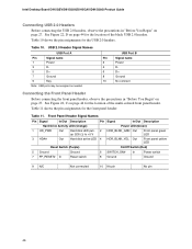
...to +5 V 3 HDA# Out Hard disk active LED Pin Signal In/Out Description Power LED (Green) 2 HDR_BLNK_GRN Out Front panel green LED 4 HDR_BLNK_YEL Out Front panel yellow LED Reset Switch (Purple) On/Off Switch (Red) 5 Ground 7 FP_RESET# In Ground Reset switch 6 SWITCH_ON# In... assignments for the location of the multi-colored front panel header. USB 2.0 Header Signal Names USB Port A Pin Signal name 1 Power 3 D- 5 D+ 7 Ground 9 Key Note: USB ports may be assigned as needed. Intel Desktop Board D915GEV/D915GUX/D915GAV/D915GAG Product Guide Connecting USB 2.0 Headers...
...to +5 V 3 HDA# Out Hard disk active LED Pin Signal In/Out Description Power LED (Green) 2 HDR_BLNK_GRN Out Front panel green LED 4 HDR_BLNK_YEL Out Front panel yellow LED Reset Switch (Purple) On/Off Switch (Red) 5 Ground 7 FP_RESET# In Ground Reset switch 6 SWITCH_ON# In... assignments for the location of the multi-colored front panel header. USB 2.0 Header Signal Names USB Port A Pin Signal name 1 Power 3 D- 5 D+ 7 Ground 9 Key Note: USB ports may be assigned as needed. Intel Desktop Board D915GEV/D915GUX/D915GAV/D915GAG Product Guide Connecting USB 2.0 Headers...
User Manual
Page 47
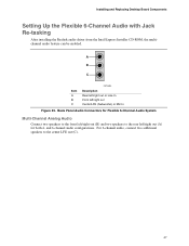
... /right out Center/LFE (Subwoofer) or Mic In Figure 23. Installing and Replacing Desktop Board Components Setting Up the Flexible 6-Channel Audio with Jack Re-tasking After installing the Realtek audio driver from the Intel Express Installer CD-ROM, the multichannel audio feature can be enabled. A B C ...Item A B C OM15694 Description Rear left/right out or Line In Front left /right out (B) and two speakers to the center LFE out (C). 47 and 6-channel audio configurations. Back Panel Audio ...
... /right out Center/LFE (Subwoofer) or Mic In Figure 23. Installing and Replacing Desktop Board Components Setting Up the Flexible 6-Channel Audio with Jack Re-tasking After installing the Realtek audio driver from the Intel Express Installer CD-ROM, the multichannel audio feature can be enabled. A B C ...Item A B C OM15694 Description Rear left/right out or Line In Front left /right out (B) and two speakers to the center LFE out (C). 47 and 6-channel audio configurations. Back Panel Audio ...
User Manual
Page 54
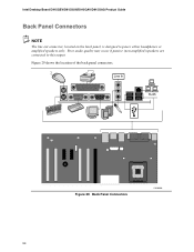
Poor audio quality may occur if passive (non-amplified) speakers are connected to power either headphones or amplified speakers only. Figure 29 shows the location of the back panel connectors. Line In RJ45 Figure 29. Intel Desktop Board D915GEV/D915GUX/D915GAV/D915GAG Product Guide Back Panel Connectors NOTE The line out connector, located on the back panel, is designed to this output. Back Panel Connectors OM16900 54
Poor audio quality may occur if passive (non-amplified) speakers are connected to power either headphones or amplified speakers only. Figure 29 shows the location of the back panel connectors. Line In RJ45 Figure 29. Intel Desktop Board D915GEV/D915GUX/D915GAV/D915GAG Product Guide Back Panel Connectors NOTE The line out connector, located on the back panel, is designed to this output. Back Panel Connectors OM16900 54
User Manual
Page 69
...When cleared, the TPM module is off the system. 9. Failure to do this can continue to operate even though the front panel power switch is disabled by default. CAUTION DATA ENCRYPTED BY ANY PROGRAM UTILIZING THE TPM WILL BECOME INACCESSIBLE IF TPM OWNERSHIP IS ...Module, press . 6. Restore power to encrypted data. (Review the Recovery Procedures for detailed instructions). Restore the configuration jumper on the desktop board can result in personal injury or equipment damage. Software Support • For assistance with the Infineon Security Platform Software, visit the ...
...When cleared, the TPM module is off the system. 9. Failure to do this can continue to operate even though the front panel power switch is disabled by default. CAUTION DATA ENCRYPTED BY ANY PROGRAM UTILIZING THE TPM WILL BECOME INACCESSIBLE IF TPM OWNERSHIP IS ...Module, press . 6. Restore power to encrypted data. (Review the Recovery Procedures for detailed instructions). Restore the configuration jumper on the desktop board can result in personal injury or equipment damage. Software Support • For assistance with the Infineon Security Platform Software, visit the ...


