User Manual
Page 3
... this Product Guide are used in this manual: WARNING Warnings indicate conditions that, if not observed, can cause personal injury. CAUTION Cautions warn the user about how to prevent damage to update the BIOS 4 Trusted Platform Module (Optional): information about setting up Trusted Platform Module 5 Desktop Board Resources: information about connectors and desktop board resources A Error Messages and Indicators: information about board layout, component installation, BIOS update, and regulatory...
... this Product Guide are used in this manual: WARNING Warnings indicate conditions that, if not observed, can cause personal injury. CAUTION Cautions warn the user about how to prevent damage to update the BIOS 4 Trusted Platform Module (Optional): information about setting up Trusted Platform Module 5 Desktop Board Resources: information about connectors and desktop board resources A Error Messages and Indicators: information about board layout, component installation, BIOS update, and regulatory...
User Manual
Page 5
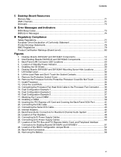
... Express Auto Configuration 23 Security Passwords...23 Chassis Intrusion...23 Power Management Features 23 ACPI...23 Power Connectors...24 Fan Connectors...24 Fan Speed Control (Intel® Precision Cooling Technology 24 Suspend to RAM (Instantly Available PC Technology 24 Resume on Ring ...25 Wake from USB ...26 Wake from PS/2 Keyboard/Mouse 26 PME# Wakeup Support 26 Speaker...26 Battery...26 Real-Time Clock...26 2 Installing and Replacing Desktop Board Components Before You Begin ...27 Installation Precautions ...28 Installation Instructions...28 Ensure Electromagnetic Compatibility...
... Express Auto Configuration 23 Security Passwords...23 Chassis Intrusion...23 Power Management Features 23 ACPI...23 Power Connectors...24 Fan Connectors...24 Fan Speed Control (Intel® Precision Cooling Technology 24 Suspend to RAM (Instantly Available PC Technology 24 Resume on Ring ...25 Wake from USB ...26 Wake from PS/2 Keyboard/Mouse 26 PME# Wakeup Support 26 Speaker...26 Battery...26 Real-Time Clock...26 2 Installing and Replacing Desktop Board Components Before You Begin ...27 Installation Precautions ...28 Installation Instructions...28 Ensure Electromagnetic Compatibility...
User Manual
Page 6
... (SATA) Cable 43 Connecting Internal Headers 44 Installing a Front Panel Audio Solution 45 Connecting USB 2.0 Headers 46 Connecting the Front Panel Header 46 Setting Up the Flexible 6-Channel Audio with Jack Re-tasking 47 Connecting Fan and Power Cables 48 Connecting Fan Cables 48 Connecting Power Cables 49 PCI Bus Add-In Card Connectors 51 Setting the BIOS Configuration Jumper Block 52 Clearing Passwords ...53 Back Panel Connectors...54 Replacing the Battery...55 3 BIOS Updating the BIOS with the Intel® Express BIOS Update Utility 59 Updating the BIOS with the Iflash Memory...
... (SATA) Cable 43 Connecting Internal Headers 44 Installing a Front Panel Audio Solution 45 Connecting USB 2.0 Headers 46 Connecting the Front Panel Header 46 Setting Up the Flexible 6-Channel Audio with Jack Re-tasking 47 Connecting Fan and Power Cables 48 Connecting Fan Cables 48 Connecting Power Cables 49 PCI Bus Add-In Card Connectors 51 Setting the BIOS Configuration Jumper Block 52 Clearing Passwords ...53 Back Panel Connectors...54 Replacing the Battery...55 3 BIOS Updating the BIOS with the Intel® Express BIOS Update Utility 59 Updating the BIOS with the Iflash Memory...
User Manual
Page 7
... the PCI Express x16 Card and Covering the Back Panel VGA Port 41 20. Connecting the IDE Cable 42 21. Back Panel LAN Connector LED Locations 20 4. Desktop Boards D915GEV and D915GAV Mounting Screw Hole Locations 31 7. Dual Configuration Example 2 37 16. Connecting 2x10 Power Supply Cables 49 26. Contents 5 Desktop Board Resources Memory Map ...71 DMA Channels ...71 Interrupts ...72 A Error Messages and Indicators BIOS Beep Codes...73 BIOS Error Messages ...74 B Regulatory Compliance Safety Regulations ...77 European Union Declaration of the PCI Bus and PCI Express...
... the PCI Express x16 Card and Covering the Back Panel VGA Port 41 20. Connecting the IDE Cable 42 21. Back Panel LAN Connector LED Locations 20 4. Desktop Boards D915GEV and D915GAV Mounting Screw Hole Locations 31 7. Dual Configuration Example 2 37 16. Connecting 2x10 Power Supply Cables 49 26. Contents 5 Desktop Board Resources Memory Map ...71 DMA Channels ...71 Interrupts ...72 A Error Messages and Indicators BIOS Beep Codes...73 BIOS Error Messages ...74 B Regulatory Compliance Safety Regulations ...77 European Union Declaration of the PCI Bus and PCI Express...
User Manual
Page 9
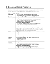
... memory address locations that reduce available memory addresses above 3 GB. Feature Summary Form Factor Processor Main Memory Chipset Graphics Audio Expansion Capabilities • ATX (12.00" x 9.60") Intel Desktop Board D915GAV/D915GEV • MicroATX (9.60" x 9.60") Intel Desktop Board D915GUX/D915GAG Support for an Intel® Pentium® 4 processor in card connectors (SMBus routed to PCI bus 2) • One PCI Express x16 connector and one PCI Express x1 connector continued 9 Table 1 summarizes the major features of : • Intel® 82915G Graphics and Memory Controller...
... memory address locations that reduce available memory addresses above 3 GB. Feature Summary Form Factor Processor Main Memory Chipset Graphics Audio Expansion Capabilities • ATX (12.00" x 9.60") Intel Desktop Board D915GAV/D915GEV • MicroATX (9.60" x 9.60") Intel Desktop Board D915GUX/D915GAG Support for an Intel® Pentium® 4 processor in card connectors (SMBus routed to PCI bus 2) • One PCI Express x16 connector and one PCI Express x1 connector continued 9 Table 1 summarizes the major features of : • Intel® 82915G Graphics and Memory Controller...
User Manual
Page 10
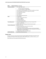
.../2* keyboard and mouse ports BIOS • Intel/AMI BIOS • 4 Mbit symmetrical flash memory • Support for SMBIOS • Intel® Rapid BIOS Boot • Intel® Express BIOS Update Power Management • Support for Advanced Configuration and Power Interface (ACPI) • Suspend to RAM (STR) • Wake on USB, PCI, PCI Express, PS/2, LAN, and front panel Hardware Management Hardware monitor with: • Three fan sensing inputs used to monitor fan activity • Remote diode temperature sensing • Intel® Precision Cooling Technology fan speed control...
.../2* keyboard and mouse ports BIOS • Intel/AMI BIOS • 4 Mbit symmetrical flash memory • Support for SMBIOS • Intel® Rapid BIOS Boot • Intel® Express BIOS Update Power Management • Support for Advanced Configuration and Power Interface (ACPI) • Suspend to RAM (STR) • Wake on USB, PCI, PCI Express, PS/2, LAN, and front panel Hardware Management Hardware monitor with: • Three fan sensing inputs used to monitor fan activity • Remote diode temperature sensing • Intel® Precision Cooling Technology fan speed control...
User Manual
Page 15
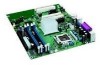
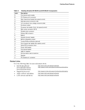
... power connector (1x4) 12 V processor core voltage connector (2x2) Processor socket Processor fan header (4-pin, fan speed control) Main power connector (2x12) Diskette drive connector Primary IDE connector Battery Chassis intrusion header BIOS configuration jumper Trusted Platform Module (optional) Front chassis fan header (fan speed control) Serial ATA connectors (four) Power LED header Front panel header USB 2.0 headers PCI bus add-in card connectors Speaker PCI Express x1 connector Related Links: Go to the following links for more information about: • Intel Desktop Board D915GEV...
... power connector (1x4) 12 V processor core voltage connector (2x2) Processor socket Processor fan header (4-pin, fan speed control) Main power connector (2x12) Diskette drive connector Primary IDE connector Battery Chassis intrusion header BIOS configuration jumper Trusted Platform Module (optional) Front chassis fan header (fan speed control) Serial ATA connectors (four) Power LED header Front panel header USB 2.0 headers PCI bus add-in card connectors Speaker PCI Express x1 connector Related Links: Go to the following links for more information about: • Intel Desktop Board D915GEV...
User Manual
Page 16
...://support.intel.com/support/motherboards/desktop/ • Instructions on installing or upgrading the processor, page 32 in Chapter 2 • The location of the two power connectors, page 48 in the LGA775 package. The processor connects to the desktop board and/or power supply. Desktop Boards D915GEV, D915GUX, D915GAV, and D915GAG support a single Intel Pentium 4 processor in Chapter 2 16 Processors are not included with the desktop board and must be purchased separately. Intel Desktop Board D915GEV/D915GUX/D915GAV/D915GAG Product Guide Processor CAUTION Failure to use...
...://support.intel.com/support/motherboards/desktop/ • Instructions on installing or upgrading the processor, page 32 in Chapter 2 • The location of the two power connectors, page 48 in the LGA775 package. The processor connects to the desktop board and/or power supply. Desktop Boards D915GEV, D915GUX, D915GAV, and D915GAG support a single Intel Pentium 4 processor in Chapter 2 16 Processors are not included with the desktop board and must be purchased separately. Intel Desktop Board D915GEV/D915GUX/D915GAV/D915GAG Product Guide Processor CAUTION Failure to use...
User Manual
Page 18
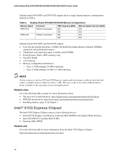
...-ECC RAM • 1.8 V memory • Memory configuration listed below: ⎯ Up to 2.0 GB utilizing 256 Mb technology ⎯ Up to the operating system and applications. Desktop Board D915GEV/D915GUX Memory Configurations Memory Speed Processor FSB frequency (MHz) Memory Speed Outcome (MHz) DDR2 533 Pentium 4 processor 800 533 533 533 DDR2 400 Pentium 4 processor 800 400 533 400 Desktop boards D915GEV and D915GUX support: • Four 240-pin Double Data Rate 2 (DDR2) SDRAM Dual Inline Memory Module (DIMMs) connectors...
...-ECC RAM • 1.8 V memory • Memory configuration listed below: ⎯ Up to 2.0 GB utilizing 256 Mb technology ⎯ Up to the operating system and applications. Desktop Board D915GEV/D915GUX Memory Configurations Memory Speed Processor FSB frequency (MHz) Memory Speed Outcome (MHz) DDR2 533 Pentium 4 processor 800 533 533 533 DDR2 400 Pentium 4 processor 800 400 533 400 Desktop boards D915GEV and D915GUX support: • Four 240-pin Double Data Rate 2 (DDR2) SDRAM Dual Inline Memory Module (DIMMs) connectors...
User Manual
Page 19
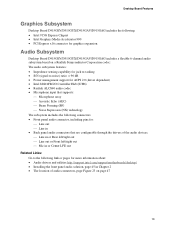
... following: • Intel 915G Express Chipset • Intel Graphics Media Accelerator 900 • PCI Express x16 connector for graphics expansion Audio Subsystem Desktop Board D915GEV/D915GUX/D915GAV/D915GAG includes a flexible 6-channel audio subsystem based on a Realtek Semiconductor Corporation codec: The audio subsystem features: • Impedance sensing capability for jack re-tasking • S/N (signal-to-noise) ratio: > 90 dB • Power management support for ACPI 2.0 (driver dependent) • Intel 82801FB I/O Controller Hub (ICH6...
... following: • Intel 915G Express Chipset • Intel Graphics Media Accelerator 900 • PCI Express x16 connector for graphics expansion Audio Subsystem Desktop Board D915GEV/D915GUX/D915GAV/D915GAG includes a flexible 6-channel audio subsystem based on a Realtek Semiconductor Corporation codec: The audio subsystem features: • Impedance sensing capability for jack re-tasking • S/N (signal-to-noise) ratio: > 90 dB • Power management support for ACPI 2.0 (driver dependent) • Intel 82801FB I/O Controller Hub (ICH6...
User Manual
Page 20
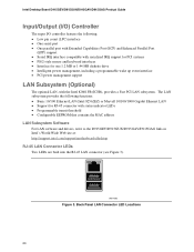
... pin count (LPC) interface • One serial port • One parallel port with Extended Capabilities Port (ECP) and Enhanced Parallel Port (EPP) support • Serial IRQ interface compatible with serialized IRQ support for PCI systems • PS/2-style mouse and keyboard interfaces • Interface for RJ-45 connector with the Intel 82801FB (ICH6), provides a Fast PCI LAN subsystem. OM17386 Figure 3. Intel Desktop Board D915GEV/D915GUX/D915GAV/D915GAG Product Guide Input/Output (I/O) Controller The...
... pin count (LPC) interface • One serial port • One parallel port with Extended Capabilities Port (ECP) and Enhanced Parallel Port (EPP) support • Serial IRQ interface compatible with serialized IRQ support for PCI systems • PS/2-style mouse and keyboard interfaces • Interface for RJ-45 connector with the Intel 82801FB (ICH6), provides a Fast PCI LAN subsystem. OM17386 Figure 3. Intel Desktop Board D915GEV/D915GUX/D915GAV/D915GAG Product Guide Input/Output (I/O) Controller The...
User Manual
Page 22
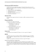
... manual configuration in the BIOS Setup program. 22 Intel Desktop Board D915GEV/D915GUX/D915GAV/D915GAG Product Guide Enhanced IDE Interface The ICH6's IDE interface handles the exchange of information between the processor and peripheral devices like hard disks, CD-ROM drives, and Iomega Zip* drives inside the computer. BIOS The BIOS provides the Power-On Self-Test (POST), the BIOS Setup program, the PCI/PCI Express and IDE auto-configuration utilities, and the video BIOS. You do not need to two IDE devices (such as hard drives...
... manual configuration in the BIOS Setup program. 22 Intel Desktop Board D915GEV/D915GUX/D915GAV/D915GAG Product Guide Enhanced IDE Interface The ICH6's IDE interface handles the exchange of information between the processor and peripheral devices like hard disks, CD-ROM drives, and Iomega Zip* drives inside the computer. BIOS The BIOS provides the Power-On Self-Test (POST), the BIOS Setup program, the PCI/PCI Express and IDE auto-configuration utilities, and the video BIOS. You do not need to two IDE devices (such as hard drives...

User Manual
Page 23
... Power management is set , you must enter either password to view and change all Setup options. A supervisor password and a user password can be set , you can enter either the supervisor password or the user password to the chassis intrusion header on the chassis that can be accessed and who can boot the computer. The use of Setup gives the user restricted access to Setup. • If both passwords are set , the computer boots without asking for a password. Desktop Board Features PCI and PCI Express Auto Configuration...
... Power management is set , you must enter either password to view and change all Setup options. A supervisor password and a user password can be set , you can enter either the supervisor password or the user password to the chassis intrusion header on the chassis that can be accessed and who can boot the computer. The use of Setup gives the user restricted access to Setup. • If both passwords are set , the computer boots without asking for a password. Desktop Board Features PCI and PCI Express Auto Configuration...
User Manual
Page 24
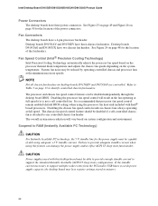
...that processor fan speed control remain enabled (default BIOS setting) when using this desktop board must be disabled independently through the desktop board BIOS. If the standby current necessary to RAM (Instantly Available PC Technology) CAUTION For Instantly Available PC technology, the 5 V standby line for the location of the fan headers. Fan Connectors The desktop boards have three chassis fan headers. Desktop boards D915GAV and D915GEV have a 4-pin processor fan header. NOTE Not all chassis fan headers on the system temperature. Disabling the processor fan speed control...
...that processor fan speed control remain enabled (default BIOS setting) when using this desktop board must be disabled independently through the desktop board BIOS. If the standby current necessary to RAM (Instantly Available PC Technology) CAUTION For Instantly Available PC technology, the 5 V standby line for the location of the fan headers. Fan Connectors The desktop boards have three chassis fan headers. Desktop boards D915GAV and D915GEV have a 4-pin processor fan header. NOTE Not all chassis fan headers on the system temperature. Disabling the processor fan speed control...
User Manual
Page 27
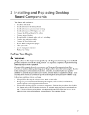
... only at an ESD workstation using and modifying electronic equipment. Follow these guidelines before you begin: • Always follow the steps in each procedure in the correct order. • Set up flexible 6-channel audio with jack re-tasking • Connect fans and power cables • Connect PCI bus add-in cards • Set the BIOS configuration jumper • Clear passwords • Locate back panel connectors • Replace the battery Before You Begin WARNINGS...
... only at an ESD workstation using and modifying electronic equipment. Follow these guidelines before you begin: • Always follow the steps in each procedure in the correct order. • Set up flexible 6-channel audio with jack re-tasking • Connect fans and power cables • Connect PCI bus add-in cards • Set the BIOS configuration jumper • Clear passwords • Locate back panel connectors • Replace the battery Before You Begin WARNINGS...
User Manual
Page 45
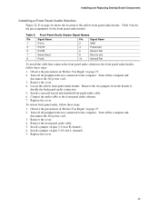
... power cord. 3. Install a jumper on page 27. 2. Remove the cover. 4. Observe the precautions in "Before You Begin" on pins 9-10 (rear L channel). 7. Connect the audio cable to the computer. Locate the yellow front panel audio header. Turn off the computer and disconnect the AC power cord. 3. Replace the cover. 45 Installing and Replacing Desktop Board Components Installing a Front Panel Audio Solution Figure 22, E on page 44 shows the location of the yellow front panel audio header. Install a correctly keyed...
... power cord. 3. Install a jumper on page 27. 2. Remove the cover. 4. Observe the precautions in "Before You Begin" on pins 9-10 (rear L channel). 7. Connect the audio cable to the computer. Locate the yellow front panel audio header. Turn off the computer and disconnect the AC power cord. 3. Replace the cover. 45 Installing and Replacing Desktop Board Components Installing a Front Panel Audio Solution Figure 22, E on page 44 shows the location of the yellow front panel audio header. Install a correctly keyed...

User Manual
Page 52
... Self-Test (POST) runs, the BIOS displays the Maintenance Menu. The BIOS recovers data from the computer before changing the jumper. Intel Desktop Board D915GEV/D915GUX/D915GAV/D915GAG Product Guide Setting the BIOS Configuration Jumper Block CAUTION Always turn off the power and unplug the power cord from a recovery diskette in the event of a failed BIOS update. 52 Jumper Settings for the BIOS Setup Program Modes Jumper Setting 1 3 Mode Normal (default) (1-2) Description The BIOS uses the current configuration and passwords for the Setup program modes. Table 12...
... Self-Test (POST) runs, the BIOS displays the Maintenance Menu. The BIOS recovers data from the computer before changing the jumper. Intel Desktop Board D915GEV/D915GUX/D915GAV/D915GAG Product Guide Setting the BIOS Configuration Jumper Block CAUTION Always turn off the power and unplug the power cord from a recovery diskette in the event of a failed BIOS update. 52 Jumper Settings for the BIOS Setup Program Modes Jumper Setting 1 3 Mode Normal (default) (1-2) Description The BIOS uses the current configuration and passwords for the Setup program modes. Table 12...

User Manual
Page 53
... power source. 11. Press to normal mode. 1. Replace the cover, plug in the computer and the configuration jumper block is installed in the computer, turn on the computer, and allow it to boot. 7. Press and Setup displays a pop-up screen requesting that the board is set to save the current values and exit Setup. 10. Remove the computer cover. 4. To restore normal operation, place the jumper on pins...
... power source. 11. Press to normal mode. 1. Replace the cover, plug in the computer and the configuration jumper block is installed in the computer, turn on the computer, and allow it to boot. 7. Press and Setup displays a pop-up screen requesting that the board is set to save the current values and exit Setup. 10. Remove the computer cover. 4. To restore normal operation, place the jumper on pins...

User Manual
Page 67
... up using the Key Transfer Manager when the removable media is necessary. Create and document the password to create the archive and restoration key files. 18. This recovery procedure may restore the migratable keys from Desktop Board or TPM Failure This procedure may restore access to Recover from Hard Disk Failure Restore the latest hard drive image from the program menu. 15. Launch the Infineon Security Platform User Initialization...
... up using the Key Transfer Manager when the removable media is necessary. Create and document the password to create the archive and restoration key files. 18. This recovery procedure may restore the migratable keys from Desktop Board or TPM Failure This procedure may restore access to Recover from Hard Disk Failure Restore the latest hard drive image from the program menu. 15. Launch the Infineon Security Platform User Initialization...
User Manual
Page 74
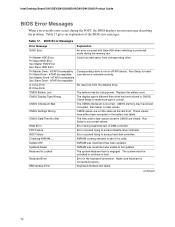
... in the keyboard connection. CMOS Display Type Wrong The display type is not an ATAPI device. Run Setup to access diskette drive controller. Make sure keyboard is selected correctly. Table 17 gives an explanation of DMA controller. FDC Failure Error occurred trying to reset values. Table 17. Checking NVRAM..... continued 74 Intel Desktop Board D915GEV/D915GUX/D915GAV/D915GAG Product Guide BIOS Error Messages When a recoverable error occurs during the memory test. Pri Master Drive - Run Setup to see...
... in the keyboard connection. CMOS Display Type Wrong The display type is not an ATAPI device. Run Setup to access diskette drive controller. Make sure keyboard is selected correctly. Table 17 gives an explanation of DMA controller. FDC Failure Error occurred trying to reset values. Table 17. Checking NVRAM..... continued 74 Intel Desktop Board D915GEV/D915GUX/D915GAV/D915GAG Product Guide BIOS Error Messages When a recoverable error occurs during the memory test. Pri Master Drive - Run Setup to see...


