User Manual
Page 22
Intel Desktop Board D915GEV/D915GUX/D915GAV/D915GAG Product Guide Enhanced IDE Interface The ICH6's IDE interface handles the exchange of information between the processor and peripheral devices like hard disks, CD-ROM drives, and Iomega Zip* drives inside the computer. The BIOS can override the auto-configuration options by following : • Desktop boards D915GAV and D915GEV ⎯ One...
Intel Desktop Board D915GEV/D915GUX/D915GAV/D915GAG Product Guide Enhanced IDE Interface The ICH6's IDE interface handles the exchange of information between the processor and peripheral devices like hard disks, CD-ROM drives, and Iomega Zip* drives inside the computer. The BIOS can override the auto-configuration options by following : • Desktop boards D915GAV and D915GEV ⎯ One...

User Manual
Page 38
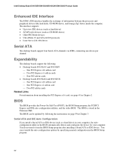
DDR DDR2 mm 1 2 3 4 5 6 7 8 9 10 11 12 13 OM16847 Figure 17. Matching the Correct DIMM 38 To make sure you have the correct DIMM, place the DIMM on the illustration in the DIMM sockets prior to installing the PCI Express video card to avoid interference with the memory retention mechanism. Intel Desktop Board D915GEV/D915GUX/D915GAV/D915GAG Product Guide Installing DIMMs CAUTION Install memory in Figure 17.
DDR DDR2 mm 1 2 3 4 5 6 7 8 9 10 11 12 13 OM16847 Figure 17. Matching the Correct DIMM 38 To make sure you have the correct DIMM, place the DIMM on the illustration in the DIMM sockets prior to installing the PCI Express video card to avoid interference with the memory retention mechanism. Intel Desktop Board D915GEV/D915GUX/D915GAV/D915GAG Product Guide Installing DIMMs CAUTION Install memory in Figure 17.
User Manual
Page 39
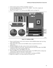
Channel A Channel B DIMM 0 DIMM 1 DIMM 0 DIMM 1 Figure 18. Position the DIMM above the socket. Installing and Replacing Desktop Board Components 1. When the DIMM is inserted, push down on page 27. 2. Make sure the clips are pushed outward to installing the DIMMs. 11. Replace ... the DIMM by the edges, remove it interferes with the keys in the socket (see Figure 18). Installing a DIMM OM16895 4. Remove the PCI Express video card if it from being easily opened and closed. 5. Align the small notch at either end of the DIMM until the retaining clips snap into...
Channel A Channel B DIMM 0 DIMM 1 DIMM 0 DIMM 1 Figure 18. Position the DIMM above the socket. Installing and Replacing Desktop Board Components 1. When the DIMM is inserted, push down on page 27. 2. Make sure the clips are pushed outward to installing the DIMMs. 11. Replace ... the DIMM by the edges, remove it interferes with the keys in the socket (see Figure 18). Installing a DIMM OM16895 4. Remove the PCI Express video card if it from being easily opened and closed. 5. Align the small notch at either end of the DIMM until the retaining clips snap into...

User Manual
Page 49
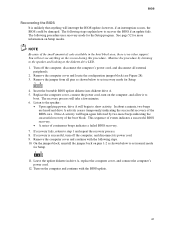
...video cards that can consume up to 75 W. Connect the 1x4 power supply cable to the 2x10 connector. Observe the precautions in damage to the 2x2 connector. 4. OM16854 49 Connect the main power supply cable to the 1x4 connector. 3. Connect the 12 V processor core voltage power supply cable to the desktop board... Power Supply Cables 1. Connecting 2x10 Power Supply Cables The 2x12 main power connector on page 27. 2. Installing and Replacing Desktop Board Components Connecting Power Cables CAUTION Failure to use an ATX12V power supply, or not connecting the 12 V (2x2) processor ...
...video cards that can consume up to 75 W. Connect the 1x4 power supply cable to the 2x10 connector. Observe the precautions in damage to the 2x2 connector. 4. OM16854 49 Connect the main power supply cable to the 1x4 connector. 3. Connect the 12 V processor core voltage power supply cable to the desktop board... Power Supply Cables 1. Connecting 2x10 Power Supply Cables The 2x12 main power connector on page 27. 2. Installing and Replacing Desktop Board Components Connecting Power Cables CAUTION Failure to use an ATX12V power supply, or not connecting the 12 V (2x2) processor ...
User Manual
Page 61
.... Insert the bootable BIOS update diskette into diskette drive A. 5. If recovery fails, return to recover the BIOS if an update fails. If recovery is no video support. You will take a few minutes. 6. Leave the update diskette in the boot block area, there is successful, turn on Setup modes. Turn on pins...
.... Insert the bootable BIOS update diskette into diskette drive A. 5. If recovery fails, return to recover the BIOS if an update fails. If recovery is no video support. You will take a few minutes. 6. Leave the update diskette in the boot block area, there is successful, turn on Setup modes. Turn on pins...

User Manual
Page 71
... Runtime BIOS Reserved Available high DOS memory (open to the PCI bus) Video memory and BIOS Extended BIOS data (movable by memory manager software) Extended conventional memory Conventional memory DMA Channels Table 14. DFFFF 640 K - 800 K 639 K - 640 K A0000 - 5 Desktop Board Resources Memory Map Table 13. EFFFF 800 K - 896 K C8000 - System Memory Map...
... Runtime BIOS Reserved Available high DOS memory (open to the PCI bus) Video memory and BIOS Extended BIOS data (movable by memory manager software) Extended conventional memory Conventional memory DMA Channels Table 14. DFFFF 640 K - 800 K 639 K - 640 K A0000 - 5 Desktop Board Resources Memory Map Table 13. EFFFF 800 K - 896 K C8000 - System Memory Map...
User Manual
Page 73
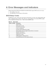
not used ) CMOS Shutdown register test error Invalid BIOS (such as, POST module not found) 73 A Error Messages and Indicators Desktop Board D915GEV/D915GUX/D915GAV/D915GAG reports POST errors in two ways: • By sounding a beep code • By displaying an error message on the ...monitor BIOS Beep Codes The BIOS also issues a beep code (one long tone followed by two short tones) during POST if the video configuration fails (a faulty video card or no card installed) or if an external ROM module does not properly checksum to zero. Beep Codes Number of Beeps 1 2 3 4 5 6 ...
not used ) CMOS Shutdown register test error Invalid BIOS (such as, POST module not found) 73 A Error Messages and Indicators Desktop Board D915GEV/D915GUX/D915GAV/D915GAG reports POST errors in two ways: • By sounding a beep code • By displaying an error message on the ...monitor BIOS Beep Codes The BIOS also issues a beep code (one long tone followed by two short tones) during POST if the video configuration fails (a faulty video card or no card installed) or if an external ROM module does not properly checksum to zero. Beep Codes Number of Beeps 1 2 3 4 5 6 ...


