User Manual
Page 3
... product features 2 Installing and Replacing Desktop Board Components: instructions on how to install the desktop board and other hardware components 3 BIOS: instructions on how to update the BIOS 4 Trusted Platform Module (Optional): information about setting up Trusted Platform Module 5 Desktop Board Resources: information about connectors and desktop board resources A Error Messages and Indicators: information about how to prevent damage to important information. CAUTION Cautions warn the user about BIOS error messages and beep codes B Regulatory...
... product features 2 Installing and Replacing Desktop Board Components: instructions on how to install the desktop board and other hardware components 3 BIOS: instructions on how to update the BIOS 4 Trusted Platform Module (Optional): information about setting up Trusted Platform Module 5 Desktop Board Resources: information about connectors and desktop board resources A Error Messages and Indicators: information about how to prevent damage to important information. CAUTION Cautions warn the user about BIOS error messages and beep codes B Regulatory...
User Manual
Page 5
... 11 Desktop Board Components 12 Processor ...16 Main Memory ...17 Intel® 915G Express Chipset 18 Graphics Subsystem ...19 Audio Subsystem ...19 Input/Output (I/O) Controller 20 LAN Subsystem (Optional)...20 LAN Subsystem Software 20 RJ-45 LAN Connector LEDs 20 Hi-Speed USB 2.0 Support 21 Enhanced IDE Interface ...22 Serial ATA ...22 Expandability...22 BIOS...22 Serial ATA and IDE Auto Configuration 22 PCI and PCI Express Auto Configuration 23 Security Passwords...23 Chassis Intrusion...23 Power Management Features 23 ACPI...23 Power Connectors...24 Fan Connectors...24 Fan Speed...
... 11 Desktop Board Components 12 Processor ...16 Main Memory ...17 Intel® 915G Express Chipset 18 Graphics Subsystem ...19 Audio Subsystem ...19 Input/Output (I/O) Controller 20 LAN Subsystem (Optional)...20 LAN Subsystem Software 20 RJ-45 LAN Connector LEDs 20 Hi-Speed USB 2.0 Support 21 Enhanced IDE Interface ...22 Serial ATA ...22 Expandability...22 BIOS...22 Serial ATA and IDE Auto Configuration 22 PCI and PCI Express Auto Configuration 23 Security Passwords...23 Chassis Intrusion...23 Power Management Features 23 ACPI...23 Power Connectors...24 Fan Connectors...24 Fan Speed...
User Manual
Page 6
... (SATA) Cable 43 Connecting Internal Headers 44 Installing a Front Panel Audio Solution 45 Connecting USB 2.0 Headers 46 Connecting the Front Panel Header 46 Setting Up the Flexible 6-Channel Audio with Jack Re-tasking 47 Connecting Fan and Power Cables 48 Connecting Fan Cables 48 Connecting Power Cables 49 PCI Bus Add-In Card Connectors 51 Setting the BIOS Configuration Jumper Block 52 Clearing Passwords ...53 Back Panel Connectors...54 Replacing the Battery...55 3 BIOS Updating the BIOS with the Intel® Express BIOS Update Utility 59 Updating the BIOS with the Iflash Memory...
... (SATA) Cable 43 Connecting Internal Headers 44 Installing a Front Panel Audio Solution 45 Connecting USB 2.0 Headers 46 Connecting the Front Panel Header 46 Setting Up the Flexible 6-Channel Audio with Jack Re-tasking 47 Connecting Fan and Power Cables 48 Connecting Fan Cables 48 Connecting Power Cables 49 PCI Bus Add-In Card Connectors 51 Setting the BIOS Configuration Jumper Block 52 Clearing Passwords ...53 Back Panel Connectors...54 Replacing the Battery...55 3 BIOS Updating the BIOS with the Intel® Express BIOS Update Utility 59 Updating the BIOS with the Iflash Memory...
User Manual
Page 7
Install Processor ...34 12. Connecting the IDE Cable 42 21. Connecting 2x12 Power Supply Cables 50 27. Desktop Boards D915GAV and D915GEV Components 12 2. Location of Fan Headers 48 25. Close the Load Plate ...34 13. Connecting the Processor Fan Heat Sink Cable to the Processor Fan Connector ........ 35 14. Dual Configuration Example 1 36 15. Matching the Correct DIMM 38 18. Inserting the PCI Express x16 Card and Covering the Back Panel VGA Port 41 20. Internal Headers ...44 23. Location of the PCI Bus and...
Install Processor ...34 12. Connecting the IDE Cable 42 21. Connecting 2x12 Power Supply Cables 50 27. Desktop Boards D915GAV and D915GEV Components 12 2. Location of Fan Headers 48 25. Close the Load Plate ...34 13. Connecting the Processor Fan Heat Sink Cable to the Processor Fan Connector ........ 35 14. Dual Configuration Example 1 36 15. Matching the Correct DIMM 38 18. Inserting the PCI Express x16 Card and Covering the Back Panel VGA Port 41 20. Internal Headers ...44 23. Location of the PCI Bus and...
User Manual
Page 9
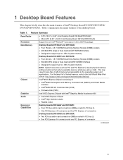
...; 4 processor in card connectors (SMBus routed to PCI bus 2) • One PCI Express x16 connector and one PCI Express x1 connector continued 9 1 Desktop Board Features This chapter briefly describes the main features of the desktop board. For the latest list of tested memory, refer to the Intel World Wide Web site at: http://support.intel.com/support/motherboards/desktop/ Intel® 915G Express Chipset consisting of system memory Desktop Boards D915GEV and D915GUX: • Four 240-pin, 1.8 V SDRAM Dual Inline Memory Module (DIMM) sockets...
...; 4 processor in card connectors (SMBus routed to PCI bus 2) • One PCI Express x16 connector and one PCI Express x1 connector continued 9 1 Desktop Board Features This chapter briefly describes the main features of the desktop board. For the latest list of tested memory, refer to the Intel World Wide Web site at: http://support.intel.com/support/motherboards/desktop/ Intel® 915G Express Chipset consisting of system memory Desktop Boards D915GEV and D915GUX: • Four 240-pin, 1.8 V SDRAM Dual Inline Memory Module (DIMM) sockets...
User Manual
Page 10
.../2* keyboard and mouse ports BIOS • Intel/AMI BIOS • 4 Mbit symmetrical flash memory • Support for SMBIOS • Intel® Rapid BIOS Boot • Intel® Express BIOS Update Power Management • Support for Advanced Configuration and Power Interface (ACPI) • Suspend to RAM (STR) • Wake on USB, PCI, PCI Express, PS/2, LAN, and front panel Hardware Management Hardware monitor with: • Three fan sensing inputs used to monitor fan activity • Remote diode temperature sensing • Intel® Precision Cooling Technology fan speed control...
.../2* keyboard and mouse ports BIOS • Intel/AMI BIOS • 4 Mbit symmetrical flash memory • Support for SMBIOS • Intel® Rapid BIOS Boot • Intel® Express BIOS Update Power Management • Support for Advanced Configuration and Power Interface (ACPI) • Suspend to RAM (STR) • Wake on USB, PCI, PCI Express, PS/2, LAN, and front panel Hardware Management Hardware monitor with: • Three fan sensing inputs used to monitor fan activity • Remote diode temperature sensing • Intel® Precision Cooling Technology fan speed control...
User Manual
Page 15
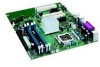
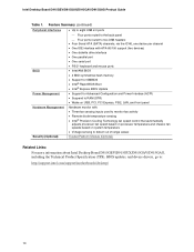
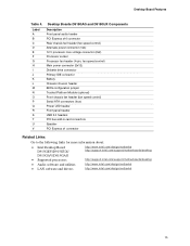
... Alternate power connector (1x4) 12 V processor core voltage connector (2x2) Processor socket Processor fan header (4-pin, fan speed control) Main power connector (2x12) Diskette drive connector Primary IDE connector Battery Chassis intrusion header BIOS configuration jumper Trusted Platform Module (optional) Front chassis fan header (fan speed control) Serial ATA connectors (four) Power LED header Front panel header USB 2.0 headers PCI bus add-in card connectors Speaker PCI Express x1 connector Related Links: Go to the following links for more information about: • Intel Desktop Board...
... Alternate power connector (1x4) 12 V processor core voltage connector (2x2) Processor socket Processor fan header (4-pin, fan speed control) Main power connector (2x12) Diskette drive connector Primary IDE connector Battery Chassis intrusion header BIOS configuration jumper Trusted Platform Module (optional) Front chassis fan header (fan speed control) Serial ATA connectors (four) Power LED header Front panel header USB 2.0 headers PCI bus add-in card connectors Speaker PCI Express x1 connector Related Links: Go to the following links for more information about: • Intel Desktop Board...
User Manual
Page 16
...) processor core voltage power supply connector to Desktop Board D915GEV/D915GUX/D915GAV/D915GAG may result in Chapter 2 16 The supported processors list for Desktop Boards D915GEV, D915GUX, D915GAV, and D915GAG is located on the web at: http://support.intel.com/support/motherboards/desktop/ Related Links: Go to the following links or pages for more information about: • Supported Intel processors for Desktop Board D915GEV/D915GUX/D915GAV/D915GAG http://support.intel.com/support/motherboards/desktop/ • Instructions on installing or upgrading the processor, page...
...) processor core voltage power supply connector to Desktop Board D915GEV/D915GUX/D915GAV/D915GAG may result in Chapter 2 16 The supported processors list for Desktop Boards D915GEV, D915GUX, D915GAV, and D915GAG is located on the web at: http://support.intel.com/support/motherboards/desktop/ Related Links: Go to the following links or pages for more information about: • Supported Intel processors for Desktop Board D915GEV/D915GUX/D915GAV/D915GAG http://support.intel.com/support/motherboards/desktop/ • Instructions on installing or upgrading the processor, page...
User Manual
Page 19
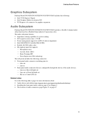
...: • Intel 915G Express Chipset • Intel Graphics Media Accelerator 900 • PCI Express x16 connector for graphics expansion Audio Subsystem Desktop Board D915GEV/D915GUX/D915GAV/D915GAG includes a flexible 6-channel audio subsystem based on a Realtek Semiconductor Corporation codec: The audio subsystem features: • Impedance sensing capability for jack re-tasking • S/N (signal-to-noise) ratio: > 90 dB • Power management support for ACPI 2.0 (driver dependent) • Intel 82801FB I/O Controller Hub (ICH6...
...: • Intel 915G Express Chipset • Intel Graphics Media Accelerator 900 • PCI Express x16 connector for graphics expansion Audio Subsystem Desktop Board D915GEV/D915GUX/D915GAV/D915GAG includes a flexible 6-channel audio subsystem based on a Realtek Semiconductor Corporation codec: The audio subsystem features: • Impedance sensing capability for jack re-tasking • S/N (signal-to-noise) ratio: > 90 dB • Power management support for ACPI 2.0 (driver dependent) • Intel 82801FB I/O Controller Hub (ICH6...
User Manual
Page 22
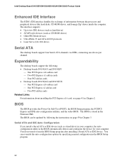
... be updated by specifying manual configuration in Chapter 3. Intel Desktop Board D915GEV/D915GUX/D915GAV/D915GAG Product Guide Enhanced IDE Interface The ICH6's IDE interface handles the exchange of information between the processor and peripheral devices like hard disks, CD-ROM drives, and Iomega Zip* drives inside the computer. The interface supports: • Up to run the BIOS Setup program after installing a Serial ATA or IDE device. The BIOS can override the auto-configuration options by following : • Desktop boards...
... be updated by specifying manual configuration in Chapter 3. Intel Desktop Board D915GEV/D915GUX/D915GAV/D915GAG Product Guide Enhanced IDE Interface The ICH6's IDE interface handles the exchange of information between the processor and peripheral devices like hard disks, CD-ROM drives, and Iomega Zip* drives inside the computer. The interface supports: • Up to run the BIOS Setup program after installing a Serial ATA or IDE device. The BIOS can override the auto-configuration options by following : • Desktop boards...

User Manual
Page 23
... chassis intrusion header. See Figure 22 on page 44 for viewing and changing depending on Ring ⎯ Wake from USB ⎯ Wake from PS/2 keyboard/mouse ⎯ PME# wakeup support ACPI ACPI gives the operating system direct control over the power management and Plug and Play functions of Setup gives the user restricted access to boot the computer. Setup options are set for the BIOS Setup and for booting the computer, with the desktop board...
... chassis intrusion header. See Figure 22 on page 44 for viewing and changing depending on Ring ⎯ Wake from USB ⎯ Wake from PS/2 keyboard/mouse ⎯ PME# wakeup support ACPI ACPI gives the operating system direct control over the power management and Plug and Play functions of Setup gives the user restricted access to boot the computer. Setup options are set for the BIOS Setup and for booting the computer, with the desktop board...
User Manual
Page 24
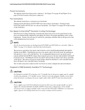
... in chassis fans always operating at the minimum necessary speeds. Failure to provide adequate standby current when using the processor fan heat-sink included with this feature can be disabled if a self-controlled chassis fan is attached to support multiple wake events from the PCI and/or USB buses exceeds power supply capacity, the desktop board may be capable of the power connectors. Suspend to support the standard Instantly Available (ACPI S3 sleep state) configuration...
... in chassis fans always operating at the minimum necessary speeds. Failure to provide adequate standby current when using the processor fan heat-sink included with this feature can be disabled if a self-controlled chassis fan is attached to support multiple wake events from the PCI and/or USB buses exceeds power supply capacity, the desktop board may be capable of the power connectors. Suspend to support the standard Instantly Available (ACPI S3 sleep state) configuration...
User Manual
Page 25
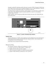
...-hand menu: http://support.intel.com/support/motherboards/desktop/ Resume on Ring The operation of Resume on the front panel, the sleep state is standby power to its last known awake state. Desktop Board Features Instantly Available PC technology enables the board to enter the ACPI S3 (Suspend-to be unmasked for correct operation 25 While in Figure 4, is lit when there is indicated by a wake-up device...
...-hand menu: http://support.intel.com/support/motherboards/desktop/ Resume on Ring The operation of Resume on the front panel, the sleep state is standby power to its last known awake state. Desktop Board Features Instantly Available PC technology enables the board to enter the ACPI S3 (Suspend-to be unmasked for correct operation 25 While in Figure 4, is lit when there is indicated by a wake-up device...
User Manual
Page 27
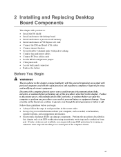
...power cables • Connect PCI bus add-in cards • Set the BIOS configuration jumper • Clear passwords • Locate back panel connectors • Replace the battery Before You Begin WARNINGS The procedures in personal injury or equipment damage. 2 Installing and Replacing Desktop Board Components This chapter tells you how to: • Install the I/O shield • Install and remove the desktop board • Install and remove a processor and memory • Install and remove a PCI Express x16 card • Connect the IDE and Serial ATA cables • Connect internal headers...
...power cables • Connect PCI bus add-in cards • Set the BIOS configuration jumper • Clear passwords • Locate back panel connectors • Replace the battery Before You Begin WARNINGS The procedures in personal injury or equipment damage. 2 Installing and Replacing Desktop Board Components This chapter tells you how to: • Install the I/O shield • Install and remove the desktop board • Install and remove a processor and memory • Install and remove a PCI Express x16 card • Connect the IDE and Serial ATA cables • Connect internal headers...
User Manual
Page 45
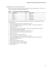
... and Replacing Desktop Board Components Installing a Front Panel Audio Solution Figure 22, E on pins 9-10 (rear L channel). 7. Turn off the computer and disconnect the AC power cord. 3. Install a correctly keyed and shielded front panel audio cable. 6. Remove the cover. 4. Table 9 shows the pin assignments for the front panel audio header. Connect the audio cable to disable the back panel audio connectors. 5. Install a jumper on page 44 shows the location of the yellow front panel audio header. Turn off all peripheral devices connected to the front panel audio header, follow...
... and Replacing Desktop Board Components Installing a Front Panel Audio Solution Figure 22, E on pins 9-10 (rear L channel). 7. Turn off the computer and disconnect the AC power cord. 3. Install a correctly keyed and shielded front panel audio cable. 6. Remove the cover. 4. Table 9 shows the pin assignments for the front panel audio header. Connect the audio cable to disable the back panel audio connectors. 5. Install a jumper on page 44 shows the location of the yellow front panel audio header. Turn off all peripheral devices connected to the front panel audio header, follow...

User Manual
Page 52
...Program Modes Jumper Setting 1 3 Mode Normal (default) (1-2) Description The BIOS uses the current configuration and passwords for the Setup program modes. Table 12. Moving the jumper with the power on may result in unreliable computer operation. The BIOS recovers data from the computer before changing the jumper. Location of the BIOS Configuration Jumper Block The three-pin BIOS jumper block enables all board configurations to clear passwords. Intel Desktop Board D915GEV/D915GUX/D915GAV/D915GAG Product Guide Setting the BIOS Configuration Jumper Block CAUTION Always turn off...
...Program Modes Jumper Setting 1 3 Mode Normal (default) (1-2) Description The BIOS uses the current configuration and passwords for the Setup program modes. Table 12. Moving the jumper with the power on may result in unreliable computer operation. The BIOS recovers data from the computer before changing the jumper. Location of the BIOS Configuration Jumper Block The three-pin BIOS jumper block enables all board configurations to clear passwords. Intel Desktop Board D915GEV/D915GUX/D915GAV/D915GAG Product Guide Setting the BIOS Configuration Jumper Block CAUTION Always turn off...

User Manual
Page 53
... Setup. 10. The computer starts the Setup program. Turn off the computer. Installing and Replacing Desktop Board Components Clearing Passwords This procedure assumes that you confirm clearing the password. Observe the precautions in the computer, and turn on pins 1-2 as shown below . 1 3 13. Turn off all peripheral devices connected to select Clear Passwords. Place the jumper on page 27. 2. Use the arrow keys to the computer. Select Yes and press . Press to boot. 7. Remove...
... Setup. 10. The computer starts the Setup program. Turn off the computer. Installing and Replacing Desktop Board Components Clearing Passwords This procedure assumes that you confirm clearing the password. Observe the precautions in the computer, and turn on pins 1-2 as shown below . 1 3 13. Turn off all peripheral devices connected to select Clear Passwords. Place the jumper on page 27. 2. Use the arrow keys to the computer. Select Yes and press . Press to boot. 7. Remove...

User Manual
Page 59
... Intel Express BIOS Update utility you can update the system BIOS while in the Windows environment. Follow the instructions provided in an automated update utility that combines the functionality of the Intel® Flash Memory Update Utility and the ease-of use of Windows-based installation wizards. The BIOS file is useful if you how to update the BIOS by pressing the key after the Power-On Self-Test (POST) memory test begins and before the operating system boot...
... Intel Express BIOS Update utility you can update the system BIOS while in the Windows environment. Follow the instructions provided in an automated update utility that combines the functionality of the Intel® Flash Memory Update Utility and the ease-of use of Windows-based installation wizards. The BIOS file is useful if you how to update the BIOS by pressing the key after the Power-On Self-Test (POST) memory test begins and before the operating system boot...

User Manual
Page 67
... system. Launch the Key Transfer Manager from Desktop Board or TPM Failure This procedure may restore access to a removable media and stored in a secure location. Restart the system. 14. no TPM specific recovery is available. 19. How to Recover from the program menu. 15. No copies of the Emergency Recovery Archive (SPEmRecArchive.xml) should not match any password changes or the addition of...
... system. Launch the Key Transfer Manager from Desktop Board or TPM Failure This procedure may restore access to a removable media and stored in a secure location. Restart the system. 14. no TPM specific recovery is available. 19. How to Recover from the program menu. 15. No copies of the Emergency Recovery Archive (SPEmRecArchive.xml) should not match any password changes or the addition of...
User Manual
Page 74
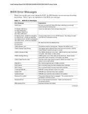
... Setup to access hard disk controller. Run Setup to make sure device is correct. Run Setup to see if it is being checked to set correct values. CMOS Settings Wrong CMOS values are invalid. Make sure keyboard is engaged. CMOS Battery Low The battery may have either been corrupted or the battery has failed. DMA Error Error during the POST, the BIOS displays an error message describing the problem. NVRAM was unable to boot. Intel Desktop Board D915GEV...
... Setup to access hard disk controller. Run Setup to make sure device is correct. Run Setup to see if it is being checked to set correct values. CMOS Settings Wrong CMOS values are invalid. Make sure keyboard is engaged. CMOS Battery Low The battery may have either been corrupted or the battery has failed. DMA Error Error during the POST, the BIOS displays an error message describing the problem. NVRAM was unable to boot. Intel Desktop Board D915GEV...


