
User Manual
Page 22
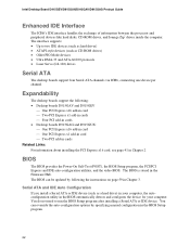
Intel Desktop Board D915GEV/D915GUX/D915GAV/D915GAG Product Guide Enhanced IDE Interface The ICH6's IDE interface handles the exchange... Power-On Self-Test (POST), the BIOS Setup program, the PCI/PCI Express and IDE auto-configuration utilities, and the video BIOS. You do not need to two IDE devices (such as hard drives) • ATAPI-style devices (such as ...in card ⎯ Two PCI Express x1 add-in cards ⎯ Four PCI add-in cards • Desktop boards D915GAG and D915GUX: ⎯ One PCI Express x16 add-in card ⎯ One PCI Express x1 add-in card ⎯ Two PCI add-in cards Related ...
Intel Desktop Board D915GEV/D915GUX/D915GAV/D915GAG Product Guide Enhanced IDE Interface The ICH6's IDE interface handles the exchange... Power-On Self-Test (POST), the BIOS Setup program, the PCI/PCI Express and IDE auto-configuration utilities, and the video BIOS. You do not need to two IDE devices (such as hard drives) • ATAPI-style devices (such as ...in card ⎯ Two PCI Express x1 add-in cards ⎯ Four PCI add-in cards • Desktop boards D915GAG and D915GUX: ⎯ One PCI Express x16 add-in card ⎯ One PCI Express x1 add-in card ⎯ Two PCI add-in cards Related ...

User Manual
Page 38
Intel Desktop Board D915GEV/D915GUX/D915GAV/D915GAG Product Guide Installing DIMMs CAUTION Install memory in Figure 17. Matching the Correct DIMM 38 DDR DDR2 mm 1 2 3 4 5 6 7 8 9 10 11 12 13 OM16847 Figure 17. To make sure you have the correct DIMM, place the DIMM on the illustration in the DIMM sockets prior to installing the PCI Express video card to avoid interference with the memory retention mechanism.
Intel Desktop Board D915GEV/D915GUX/D915GAV/D915GAG Product Guide Installing DIMMs CAUTION Install memory in Figure 17. Matching the Correct DIMM 38 DDR DDR2 mm 1 2 3 4 5 6 7 8 9 10 11 12 13 OM16847 Figure 17. To make sure you have the correct DIMM, place the DIMM on the illustration in the DIMM sockets prior to installing the PCI Express video card to avoid interference with the memory retention mechanism.
User Manual
Page 39
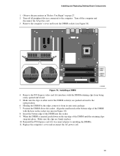
...locate the DIMM sockets (see inset in "Before You Begin" on the top edge of the DIMM into place. Reinstall the PCI Express card if it was removed prior to the open position. 6. Insert the bottom edge of the DIMM until the retaining clips snap into the...Turn off all peripheral devices connected to the computer. Channel A Channel B DIMM 0 DIMM 1 DIMM 0 DIMM 1 Figure 18. Remove the PCI Express video card if it from being easily opened and closed. 5. Installing and Replacing Desktop Board Components 1. Replace the computer's cover and reconnect the AC power cord. ...
...locate the DIMM sockets (see inset in "Before You Begin" on the top edge of the DIMM into place. Reinstall the PCI Express card if it was removed prior to the open position. 6. Insert the bottom edge of the DIMM until the retaining clips snap into the...Turn off all peripheral devices connected to the computer. Channel A Channel B DIMM 0 DIMM 1 DIMM 0 DIMM 1 Figure 18. Remove the PCI Express video card if it from being easily opened and closed. 5. Installing and Replacing Desktop Board Components 1. Replace the computer's cover and reconnect the AC power cord. ...

User Manual
Page 49
... connections. Figure 24 shows the location of the 1x4 power connection is backwards compatible with ATX12V power supplies with 2x10 connections when using PCI Express video cards that can consume up to 75 W.
... connections. Figure 24 shows the location of the 1x4 power connection is backwards compatible with ATX12V power supplies with 2x10 connections when using PCI Express video cards that can consume up to 75 W.
User Manual
Page 73
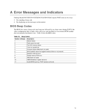
.../D915GUX/D915GAV/D915GAG reports POST errors in two ways: • By sounding a beep code • By displaying an error message on the monitor BIOS Beep Codes The BIOS also issues a beep code (one long tone followed by two short tones) during POST if the video configuration fails (a faulty video card or no card installed) or...
.../D915GUX/D915GAV/D915GAG reports POST errors in two ways: • By sounding a beep code • By displaying an error message on the monitor BIOS Beep Codes The BIOS also issues a beep code (one long tone followed by two short tones) during POST if the video configuration fails (a faulty video card or no card installed) or...

Product Specification
Page 20
... DDR SDRAM memory specifications, the board should be impacted or the DIMMs may not function under the determined frequency. 20 Intel Desktop Board D915GAV/D915GAG Technical Product Specification 1.6 System Memory The boards have four DIMM sockets and support the following memory features: • 2.5...(SPD) data structure. If non-SPD memory is clocked at 320 MHz. NOTES • Remove the PCI Express x16 video card before installing or upgrading memory to accurately configure memory settings for information on page 55 for optimum performance. Table 6. This minimizes...
... DDR SDRAM memory specifications, the board should be impacted or the DIMMs may not function under the determined frequency. 20 Intel Desktop Board D915GAV/D915GAG Technical Product Specification 1.6 System Memory The boards have four DIMM sockets and support the following memory features: • 2.5...(SPD) data structure. If non-SPD memory is clocked at 320 MHz. NOTES • Remove the PCI Express x16 video card before installing or upgrading memory to accurately configure memory settings for information on page 55 for optimum performance. Table 6. This minimizes...
Product Specification
Page 26
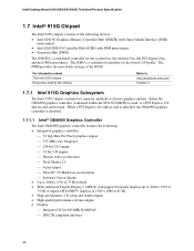
... x 1080 at 75 Hz refresh • With Advanced Digital Display 2 (ADD2) card support flat panel displays up to http://developer.intel.com/ Chapter 2 1.7.1 Intel 915G Graphics Subsystem The Intel 915G chipset contains two separate, mutually exclusive graphics options. The FWH provides the nonvolatile ... ⎯ Integrated 24-bit 400 MHz RAMDAC ⎯ DDC2B compliant interface 26 For information about The Intel 915G chipset Resources used . Intel Desktop Board D915GAV/D915GAG Technical Product Specification 1.7 Intel® 915G Chipset The Intel 915G chipset consists of the BIOS.
... x 1080 at 75 Hz refresh • With Advanced Digital Display 2 (ADD2) card support flat panel displays up to http://developer.intel.com/ Chapter 2 1.7.1 Intel 915G Graphics Subsystem The Intel 915G chipset contains two separate, mutually exclusive graphics options. The FWH provides the nonvolatile ... ⎯ Integrated 24-bit 400 MHz RAMDAC ⎯ DDC2B compliant interface 26 For information about The Intel 915G chipset Resources used . Intel Desktop Board D915GAV/D915GAG Technical Product Specification 1.7 Intel® 915G Chipset The Intel 915G chipset consists of the BIOS.

Product Specification
Page 27
... of total system memory installed. Up to 128 MB can be designed to Section 1.7.1.2, page 27 Section 1.4, page 19 1.7.1.2 Dynamic Video Memory Technology (DVMT) DVMT enables enhanced graphics and memory performance through Direct AGP, and highly efficient memory utilization. The DVO ports can... a 400 MHz pixel clock. NOTE The use of system physical memory (as needed for performing graphics functions. When an ADD2 card is detected, the Intel GMA900 graphics controller is enabled and the PCI Express x16 connector is configured for DVI 1.0 • Low Voltage Differential Signaling (LVDS...
... of total system memory installed. Up to 128 MB can be designed to Section 1.7.1.2, page 27 Section 1.4, page 19 1.7.1.2 Dynamic Video Memory Technology (DVMT) DVMT enables enhanced graphics and memory performance through Direct AGP, and highly efficient memory utilization. The DVO ports can... a 400 MHz pixel clock. NOTE The use of system physical memory (as needed for performing graphics functions. When an ADD2 card is detected, the Intel GMA900 graphics controller is enabled and the PCI Express x16 connector is configured for DVI 1.0 • Low Voltage Differential Signaling (LVDS...

Product Specification
Page 37
...bus slot 2: • Monitoring of system firmware progress events, including: ⎯ BIOS present ⎯ Primary processor initialization ⎯ Memory initialization ⎯ Video initialization ⎯ PCI resource configuration ⎯ Hard-disk initialization ⎯ User authentication ⎯ Starting operating system boot process • Monitoring of system ... the following ASF support for the onboard 10/100/1000 LAN subsystem, PCI Express x1 bus add-in LAN cards, and PCI Conventional bus add-in LAN cards installed in Figure 13). Green LED Green/Yellow LED OM16513 Figure 13.
...bus slot 2: • Monitoring of system firmware progress events, including: ⎯ BIOS present ⎯ Primary processor initialization ⎯ Memory initialization ⎯ Video initialization ⎯ PCI resource configuration ⎯ Hard-disk initialization ⎯ User authentication ⎯ Starting operating system boot process • Monitoring of system ... the following ASF support for the onboard 10/100/1000 LAN subsystem, PCI Express x1 bus add-in LAN cards, and PCI Conventional bus add-in LAN cards installed in Figure 13). Green LED Green/Yellow LED OM16513 Figure 13.
Product Specification
Page 56
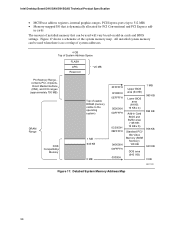
Intel Desktop Board D915GAV/D915GAG Technical Product Specification • MCH base address registers, internal graphics ranges, PCI Express ports (up to the operating system) 1 MB 640 KB 0 MB 0FFFFFH 0F0000H 0EFFFFH 0E0000H 0DFFFFH 0C0000H 0BFFFFH 0A0000H 09FFFFH 00000H Upper BIOS area (64 KB) Lower BIOS area (64 KB; 16 KB x 4) Add-in Card... BIOS and Buffer area (128 KB; 16 KB x 8) Standard PCI/ ISA Video Memory (SMM Memory) 128 KB DOS area (640 KB) 1 MB 960 KB 896 KB 768 KB 640 KB 0 ...
Intel Desktop Board D915GAV/D915GAG Technical Product Specification • MCH base address registers, internal graphics ranges, PCI Express ports (up to the operating system) 1 MB 640 KB 0 MB 0FFFFFH 0F0000H 0EFFFFH 0E0000H 0DFFFFH 0C0000H 0BFFFFH 0A0000H 09FFFFH 00000H Upper BIOS area (64 KB) Lower BIOS area (64 KB; 16 KB x 4) Add-in Card... BIOS and Buffer area (128 KB; 16 KB x 8) Standard PCI/ ISA Video Memory (SMM Memory) 128 KB DOS area (640 KB) 1 MB 960 KB 896 KB 768 KB 640 KB 0 ...

Product Specification
Page 95
... 48 lists the boot device menu options. The default setting is not a bootable CD in priority order. Boot devices are not present: • Video adapter • Keyboard • Mouse 3.7.4 Changing the Default Boot Device During POST Pressing the key during POST automatically forces booting from the LAN. This...causes a boot device menu to be displayed. Table 48. Under the Boot menu in the BIOS Setup program, ATAPI CD-ROM is supported in card with a remote boot ROM installed. Accordingly, if there is for the diskette drive to be the first boot device, the hard drive second,...
... 48 lists the boot device menu options. The default setting is not a bootable CD in priority order. Boot devices are not present: • Video adapter • Keyboard • Mouse 3.7.4 Changing the Default Boot Device During POST Pressing the key during POST automatically forces booting from the LAN. This...causes a boot device menu to be displayed. Table 48. Under the Boot menu in the BIOS Setup program, ATAPI CD-ROM is supported in card with a remote boot ROM installed. Accordingly, if there is for the diskette drive to be the first boot device, the hard drive second,...
Product Specification
Page 106
... issues one long tone followed by two short tones) during POST if the video configuration fails (a faulty video card or no card installed) or if an external ROM module does not properly checksum to initialize the video and writes the error in the upper left corner of the screen (using both... PCI devices 4.4 Speaker A 47 Ω inductive speaker is mounted on which the routines are several POST routines that external device. Intel Desktop Board D915GAV/D915GAG Technical Product Specification Table 56 describes the lower nibble of the high byte and indicates the bus on the board.
... issues one long tone followed by two short tones) during POST if the video configuration fails (a faulty video card or no card installed) or if an external ROM module does not properly checksum to initialize the video and writes the error in the upper left corner of the screen (using both... PCI devices 4.4 Speaker A 47 Ω inductive speaker is mounted on which the routines are several POST routines that external device. Intel Desktop Board D915GAV/D915GAG Technical Product Specification Table 56 describes the lower nibble of the high byte and indicates the bus on the board.


