Product Guide
Page 6
Intel Desktop Board D875PBZ Product Guide Installing the I/O Shield...30 Installing and Removing the Desktop Board 31 Installing and Removing a Processor 32 Installing a Processor 32 Installing the Processor Fan Heat Sink 32 Connecting the Processor Fan ..., and Resetting RAID Sets 41 Loading the Intel® Application Accelerator 3.0 RAID Edition Driver 42 Configuring an Intel RAID Ready System 42 Upgrading to Serial ATA RAID 0 Configuration from a Single Drive Configuration......43 Connecting Internal Headers 44 Connecting the Front Panel Header 44 Connecting the USB 2.0 Header 45...
Intel Desktop Board D875PBZ Product Guide Installing the I/O Shield...30 Installing and Removing the Desktop Board 31 Installing and Removing a Processor 32 Installing a Processor 32 Installing the Processor Fan Heat Sink 32 Connecting the Processor Fan ..., and Resetting RAID Sets 41 Loading the Intel® Application Accelerator 3.0 RAID Edition Driver 42 Configuring an Intel RAID Ready System 42 Upgrading to Serial ATA RAID 0 Configuration from a Single Drive Configuration......43 Connecting Internal Headers 44 Connecting the Front Panel Header 44 Connecting the USB 2.0 Header 45...

Product Guide
Page 7
... Hard Disk Drives Submenu 83 Removable Devices Submenu 84 ATAPI CD-ROM Drives 85 Exit Menu ...86 5 Technical Reference Back Panel Connectors ...88 Add-In Card and Peripheral Interface Connectors 89 Desktop Board Resources 90 Memory Map ...90 DMA Channels ...90 Interrupts ...91 A Error Messages and Indicators BIOS Beep Codes ...93 BIOS Error...
... Hard Disk Drives Submenu 83 Removable Devices Submenu 84 ATAPI CD-ROM Drives 85 Exit Menu ...86 5 Technical Reference Back Panel Connectors ...88 Add-In Card and Peripheral Interface Connectors 89 Desktop Board Resources 90 Memory Map ...90 DMA Channels ...90 Interrupts ...91 A Error Messages and Indicators BIOS Beep Codes ...93 BIOS Error...

Product Guide
Page 8
...75 24. Boot Menu...81 viii I/O Shield ...30 4. Dual Configuration Example with Two DIMMs 35 9. Location of the Desktop Board Mounting Screw Holes 31 5. Back Panel Connectors...88 18. USB 2.0 Header (J8J1) ...45 6. Maintenance Menu...58 10. Boot Configuration Submenu 62 14. ...Submenu 61 13. IDE Configuration Submenu 65 16. Video Configuration Submenu 70 20. Intel Desktop Board D875PBZ Product Guide Figures 1. RJ-45 10/100/1000 Gigabit Ethernet LAN Connector LEDs 19 4. Front Panel Header (J8J3 44 5. Event Log Configuration Submenu 69 19. Connecting the Processor ...
...75 24. Boot Menu...81 viii I/O Shield ...30 4. Dual Configuration Example with Two DIMMs 35 9. Location of the Desktop Board Mounting Screw Holes 31 5. Back Panel Connectors...88 18. USB 2.0 Header (J8J1) ...45 6. Maintenance Menu...58 10. Boot Configuration Submenu 62 14. ...Submenu 61 13. IDE Configuration Submenu 65 16. Video Configuration Submenu 70 20. Intel Desktop Board D875PBZ Product Guide Figures 1. RJ-45 10/100/1000 Gigabit Ethernet LAN Connector LEDs 19 4. Front Panel Header (J8J3 44 5. Event Log Configuration Submenu 69 19. Connecting the Processor ...
Product Guide
Page 11
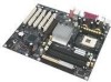
... latest list of tested memory, refer to the Intel World Wide Web site at: http://support.intel.com/support/motherboards/desktop Intel® 875P chipset featuring Intel® Performance Acceleration Technology (PAT) and consisting of...Intel® Pentium® 4 processor in card connectors (SMBus routed to PCI bus 2) • One AGP 8x connector • Up to eight USB 2.0 ports Six ports routed to the back panel Two ports routed to 4 GB of the desktop board. 1 Desktop Board Features This chapter briefly describes the main features of Intel® Desktop Board D875PBZ...
... latest list of tested memory, refer to the Intel World Wide Web site at: http://support.intel.com/support/motherboards/desktop Intel® 875P chipset featuring Intel® Performance Acceleration Technology (PAT) and consisting of...Intel® Pentium® 4 processor in card connectors (SMBus routed to PCI bus 2) • One AGP 8x connector • Up to eight USB 2.0 ports Six ports routed to the back panel Two ports routed to 4 GB of the desktop board. 1 Desktop Board Features This chapter briefly describes the main features of Intel® Desktop Board D875PBZ...
Product Guide
Page 12
...and front panel Hardware Management • Hardware monitor with: • Four fan sensing inputs used to monitor fan activity • Remote diode temperature sensing • Intel® ...Precision Cooling Technology fan speed control that automatically adjusts chassis fan speeds based on system temperature • Voltage sensing to detect out of range values Related Links: For more information about Intel Desktop Board D875PBZ, including the Technical Product Specification (TPS), BIOS updates, and device drivers, go to: http://support.intel.com/support/motherboards/desktop...
...and front panel Hardware Management • Hardware monitor with: • Four fan sensing inputs used to monitor fan activity • Remote diode temperature sensing • Intel® ...Precision Cooling Technology fan speed control that automatically adjusts chassis fan speeds based on system temperature • Voltage sensing to detect out of range values Related Links: For more information about Intel Desktop Board D875PBZ, including the Technical Product Specification (TPS), BIOS updates, and device drivers, go to: http://support.intel.com/support/motherboards/desktop...

Product Guide
Page 15
... 2.0 header R Front panel header S Speaker T Power LED header U Chassis intrusion header V Battery W Intel 82801ER (ICH5R) X PCI bus add-in card connectors Related Links: Go to the following links for more information about: • Intel Desktop Board D875PBZ http://www.intel.com/design/motherbd http://support.intel.com/support/motherboards/desktop • supported processors http://support.intel.com/support/motherboards/desktop • audio software...
... 2.0 header R Front panel header S Speaker T Power LED header U Chassis intrusion header V Battery W Intel 82801ER (ICH5R) X PCI bus add-in card connectors Related Links: Go to the following links for more information about: • Intel Desktop Board D875PBZ http://www.intel.com/design/motherbd http://support.intel.com/support/motherboards/desktop • supported processors http://support.intel.com/support/motherboards/desktop • audio software...
Product Guide
Page 19
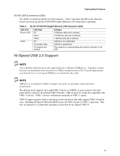
Desktop Board Features RJ-45 LAN Connector LEDs Two LEDs are limited to USB...sec data rate is established. On (steady state) LAN link is selected. Table 3 describes the LED states when the board is attached to accommodate operating systems that fully support USB 2.0 transfer rates. USB 1.1 devices will function normally at USB...the requirements for a full-speed USB device. The desktop board supports up and the 10/100/1000 Gigabit Ethernet LAN subsystem is communicating with USB 1.1 devices. six ports routed to the back panel and two routed to USB 1.1 operation. Table 3....
Desktop Board Features RJ-45 LAN Connector LEDs Two LEDs are limited to USB...sec data rate is established. On (steady state) LAN link is selected. Table 3 describes the LED states when the board is attached to accommodate operating systems that fully support USB 2.0 transfer rates. USB 1.1 devices will function normally at USB...the requirements for a full-speed USB device. The desktop board supports up and the 10/100/1000 Gigabit Ethernet LAN subsystem is communicating with USB 1.1 devices. six ports routed to the back panel and two routed to USB 1.1 operation. Table 3....

Product Guide
Page 23
... the front panel, the sleep state is standby power to support the standard Instantly Available (ACPI S3 sleep state) configuration. If the standby current necessary to the TPS by selecting the Technical Documentation link at: http://developer.intel.com/design/motherbd/ Power Connectors The desktop board has two power connectors. Desktop Board Features The desktop board's standby power...
... the front panel, the sleep state is standby power to support the standard Instantly Available (ACPI S3 sleep state) configuration. If the standby current necessary to the TPS by selecting the Technical Documentation link at: http://developer.intel.com/design/motherbd/ Power Connectors The desktop board has two power connectors. Desktop Board Features The desktop board's standby power...

Product Guide
Page 27
...though the front panel power button is not available, you can provide some ESD protection by wearing an antistatic wrist strap and attaching it to a metal part of the procedures described in personal injury or equipment damage. 2 Installing and Replacing Desktop Board Components This ...• Install the I/O shield • Install and remove the desktop board • Install and remove a processor and memory • Install and remove an AGP card • Connect the IDE and Serial ATA cables • Configure Intel RAID Technology • Connect internal headers • Connect fans and...
...though the front panel power button is not available, you can provide some ESD protection by wearing an antistatic wrist strap and attaching it to a metal part of the procedures described in personal injury or equipment damage. 2 Installing and Replacing Desktop Board Components This ...• Install the I/O shield • Install and remove the desktop board • Install and remove a processor and memory • Install and remove an AGP card • Connect the IDE and Serial ATA cables • Configure Intel RAID Technology • Connect internal headers • Connect fans and...
Product Guide
Page 37
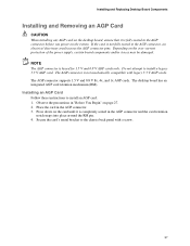
...AGP connector is not fully seated in the AGP connector. 3. Secure the card's metal bracket to the chassis back panel with legacy 3.3 V AGP cards. The desktop board has an integrated AGP card retention mechanism (RM). Installing and Replacing Desktop Board Components Installing and Removing an AGP Card CAUTION When installing any AGP card on the... desktop board, ensure that it is completely seated in the AGP connector and the card retention notch snaps into place around the RM pin. 4. Observe the ...
...AGP connector is not fully seated in the AGP connector. 3. Secure the card's metal bracket to the chassis back panel with legacy 3.3 V AGP cards. The desktop board has an integrated AGP card retention mechanism (RM). Installing and Replacing Desktop Board Components Installing and Removing an AGP Card CAUTION When installing any AGP card on the... desktop board, ensure that it is completely seated in the AGP connector and the card retention notch snaps into place around the RM pin. 4. Observe the ...

Product Guide
Page 38
Observe the precautions in the card. 4. Removing the AGP card OM15479 38 Push back on the RM lever (D), as shown in Figure 10, until the retention pin (C) completely clears the notch in "Before You Begin" on page 27. 2. Pull the card straight up (E). Intel Desktop Board D875PBZ Product Guide Removing the AGP Card Follow these instructions to the chassis back panel. 3. B D A C Figure 10. Remove the screw (B) that secures the card's metal bracket (A) to remove the AGP card from the RM: 1.
Observe the precautions in the card. 4. Removing the AGP card OM15479 38 Push back on the RM lever (D), as shown in Figure 10, until the retention pin (C) completely clears the notch in "Before You Begin" on page 27. 2. Pull the card straight up (E). Intel Desktop Board D875PBZ Product Guide Removing the AGP Card Follow these instructions to the chassis back panel. 3. B D A C Figure 10. Remove the screw (B) that secures the card's metal bracket (A) to remove the AGP card from the RM: 1.

Product Guide
Page 44
...;) to the internal headers, observe the precautions in "Before You Begin" on page 27. 3 1 J9J1 A 9 8 7 6 5 4 3 2 1 J8J3 B 10 8 7 6 5 4 3 2 1 J8J1 C Item A B C Description Alternate power/sleep LED Front panel USB 2.0 Figure 13. Intel Desktop Board D875PBZ Product Guide Connecting Internal Headers Before connecting cables to +5 V LED 3 HDA# Out Hard disk active LED 4 HDR_BLNK_YEL Out Front...
...;) to the internal headers, observe the precautions in "Before You Begin" on page 27. 3 1 J9J1 A 9 8 7 6 5 4 3 2 1 J8J3 B 10 8 7 6 5 4 3 2 1 J8J1 C Item A B C Description Alternate power/sleep LED Front panel USB 2.0 Figure 13. Intel Desktop Board D875PBZ Product Guide Connecting Internal Headers Before connecting cables to +5 V LED 3 HDA# Out Hard disk active LED 4 HDR_BLNK_YEL Out Front...

Product Guide
Page 87
A fault in board and peripheral interface connectors CAUTION Many of the midboard and front panel connectors provide operating voltage (+5 V dc and +12 V dc, for powering devices external to the computer chassis. 5 Technical Reference This chapter shows the location of the: • Back panel connectors • Add-in the load presented by the external devices...
A fault in board and peripheral interface connectors CAUTION Many of the midboard and front panel connectors provide operating voltage (+5 V dc and +12 V dc, for powering devices external to the computer chassis. 5 Technical Reference This chapter shows the location of the: • Back panel connectors • Add-in the load presented by the external devices...

Product Guide
Page 88
Poor audio quality may occur if passive (non-amplified) speakers are connected to power either headphones or amplified speakers only. Back Panel Connectors OM15695 88 Intel Desktop Board D875PBZ Product Guide Back Panel Connectors NOTE The line out connector, located on the back panel, is designed to this output. Figure 17 shows the back panel connectors. USB 2.0 Devices RJ45 USB 2.0 Devices Figure 17.
Poor audio quality may occur if passive (non-amplified) speakers are connected to power either headphones or amplified speakers only. Back Panel Connectors OM15695 88 Intel Desktop Board D875PBZ Product Guide Back Panel Connectors NOTE The line out connector, located on the back panel, is designed to this output. Figure 17 shows the back panel connectors. USB 2.0 Devices RJ45 USB 2.0 Devices Figure 17.


