Product Guide
Page 6
..., and Resetting RAID Sets 41 Loading the Intel® Application Accelerator 3.0 RAID Edition Driver 42 Configuring an Intel RAID Ready System 42 Upgrading to Serial ATA RAID 0 Configuration from a Single Drive Configuration......43 Connecting Internal Headers 44 Connecting the Front Panel Header 44 Connecting the USB 2.0 Header 45 Connecting Hardware Control and Power Cables 46 Connecting Hardware Control Cables 47 Connecting Power Cables 47 Setting the BIOS Configuration Jumper Block 48 Clearing Passwords ...49 Replacing the Battery ...50 3 Updating the BIOS Updating the BIOS with...
..., and Resetting RAID Sets 41 Loading the Intel® Application Accelerator 3.0 RAID Edition Driver 42 Configuring an Intel RAID Ready System 42 Upgrading to Serial ATA RAID 0 Configuration from a Single Drive Configuration......43 Connecting Internal Headers 44 Connecting the Front Panel Header 44 Connecting the USB 2.0 Header 45 Connecting Hardware Control and Power Cables 46 Connecting Hardware Control Cables 47 Connecting Power Cables 47 Setting the BIOS Configuration Jumper Block 48 Clearing Passwords ...49 Replacing the Battery ...50 3 Updating the BIOS Updating the BIOS with...

Product Guide
Page 8
... 3. USB 2.0 Header (J8J1) ...45 6. PCI Configuration Submenu 61 13. Primary/Secondary IDE Master/Slave Submenus 66 17. Hardware Management...74 23. Add-In Card and Peripheral Interface Connectors 89 Tables 1. Power Menu...77 26. Connecting the IDE Cable 39 12. Hardware Monitoring Submenu 75 24. Desktop Board Components 14 2. Replacing the Battery...52 17. Jumper Settings for the BIOS Setup Program Modes (J9J4 48 7. Dual Configuration Example with Two DIMMs 35 9. Intel Desktop Board D875PBZ Product Guide Figures 1. Installing a Processor...32...
... 3. USB 2.0 Header (J8J1) ...45 6. PCI Configuration Submenu 61 13. Primary/Secondary IDE Master/Slave Submenus 66 17. Hardware Management...74 23. Add-In Card and Peripheral Interface Connectors 89 Tables 1. Power Menu...77 26. Connecting the IDE Cable 39 12. Hardware Monitoring Submenu 75 24. Desktop Board Components 14 2. Replacing the Battery...52 17. Jumper Settings for the BIOS Setup Program Modes (J9J4 48 7. Dual Configuration Example with Two DIMMs 35 9. Intel Desktop Board D875PBZ Product Guide Figures 1. Installing a Processor...32...

Product Guide
Page 15
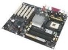
... Rear chassis fan header (fan speed control) C 12 V processor core voltage connector D VREG fan header E Processor socket F Processor fan header G Intel 82875P (MCH) H DIMM sockets I Main power connector J Diskette drive connector K Primary IDE connector L Secondary IDE connector M SCSI LED header N Front chassis fan header (fan speed control) O Serial ATA headers P BIOS configuration jumper Q USB 2.0 header R Front panel header S Speaker T Power LED header U Chassis intrusion header V Battery W Intel 82801ER (ICH5R) X PCI bus add-in card connectors...
... Rear chassis fan header (fan speed control) C 12 V processor core voltage connector D VREG fan header E Processor socket F Processor fan header G Intel 82875P (MCH) H DIMM sockets I Main power connector J Diskette drive connector K Primary IDE connector L Secondary IDE connector M SCSI LED header N Front chassis fan header (fan speed control) O Serial ATA headers P BIOS configuration jumper Q USB 2.0 header R Front panel header S Speaker T Power LED header U Chassis intrusion header V Battery W Intel 82801ER (ICH5R) X PCI bus add-in card connectors...
Product Guide
Page 16
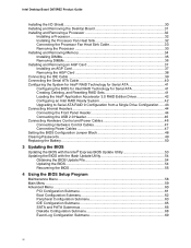
... to the Intel 875P chipset and Intel Pentium 4 processor. The board has two ATX12V compliant power supply connectors that are not included with the desktop board and must be removed and replaced to the Intel desktop board through the mPGA478-pin socket. Table 2. Desktop Board D875PBZ supports a single Intel Pentium 4 processor. The processor connects to accommodate supported higher speed processors. Desktop Board D875PBZ supports the processors listed in Chapter 2 • the location of the two power connectors, see Figure 14 on installing or upgrading the processor, see page...
... to the Intel 875P chipset and Intel Pentium 4 processor. The board has two ATX12V compliant power supply connectors that are not included with the desktop board and must be removed and replaced to the Intel desktop board through the mPGA478-pin socket. Table 2. Desktop Board D875PBZ supports a single Intel Pentium 4 processor. The processor connects to accommodate supported higher speed processors. Desktop Board D875PBZ supports the processors listed in Chapter 2 • the location of the two power connectors, see Figure 14 on installing or upgrading the processor, see page...

Product Guide
Page 17
... dual channel 184-pin Double Data Rate (DDR) SDRAM DIMMs connectors with DIMMs that reduce available memory addresses above 3 GB. This may result in BIOS) 2.5 V memory • Support for 128 Mb, 256 Mb, and 512 Mb memory technologies for more information about: • the latest list of memory being available to this effect on the screen at power up. Supported memory configurations are: Memory Speed Processor FSB Memory Speed Outcome DDR400 Intel...
... dual channel 184-pin Double Data Rate (DDR) SDRAM DIMMs connectors with DIMMs that reduce available memory addresses above 3 GB. This may result in BIOS) 2.5 V memory • Support for 128 Mb, 256 Mb, and 512 Mb memory technologies for more information about: • the latest list of memory being available to this effect on the screen at power up. Supported memory configurations are: Memory Speed Processor FSB Memory Speed Outcome DDR400 Intel...

Product Guide
Page 18
... Enhanced Parallel Port (EPP) support • Serial IRQ interface compatible with serialized IRQ support for PCI systems • PS/2-style mouse and keyboard interfaces • Interface for LAN software and drivers: http://support.intel.com/support/motherboards/desktop 18 it requires processors with status indicator LEDs LAN Subsystem Software Go to the following : • 10/100/1000 Gigabit Ethernet (Intel 82547EI) • Direct link to the memory controller hub with CSA • Configurable EEPROM...
... Enhanced Parallel Port (EPP) support • Serial IRQ interface compatible with serialized IRQ support for PCI systems • PS/2-style mouse and keyboard interfaces • Interface for LAN software and drivers: http://support.intel.com/support/motherboards/desktop 18 it requires processors with status indicator LEDs LAN Subsystem Software Go to the following : • 10/100/1000 Gigabit Ethernet (Intel 82547EI) • Direct link to the memory controller hub with CSA • Configurable EEPROM...

Product Guide
Page 20
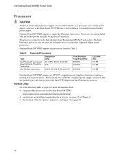
...) drives SCSI LED Connector The SCSI hard drive LED connector is keyed for graphics-intensive applications, such as the onboard IDE controller. The controller supports: • Transfer rate of 150 MB/sec • Up to two SATA devices • RAID 0 (striping) support (for Windows XP only) • PIO and DMA modes Accelerated Graphics Port (AGP) NOTE The AGP connector is a 1x2-pin connector that allows an add-in SCSI controller (or other add-in card hard drive controller) to install a legacy 3.3 V AGP card. Serial...
...) drives SCSI LED Connector The SCSI hard drive LED connector is keyed for graphics-intensive applications, such as the onboard IDE controller. The controller supports: • Transfer rate of 150 MB/sec • Up to two SATA devices • RAID 0 (striping) support (for Windows XP only) • PIO and DMA modes Accelerated Graphics Port (AGP) NOTE The AGP connector is a 1x2-pin connector that allows an add-in SCSI controller (or other add-in card hard drive controller) to install a legacy 3.3 V AGP card. Serial...
Product Guide
Page 21
... card. IDE Auto Configuration If you install an IDE device (such as a hard drive) in your computer, the IDE auto-configuration utility in the BIOS automatically detects and configures the device for booting the computer, with the following items are set , you must enter either password to boot the computer. 21 A supervisor password and a user password can be accessed and who can override the autoconfiguration options by specifying manual configuration in the BIOS Setup program. Desktop Board Features PCI Auto Configuration If you install a PCI add-in card...
... card. IDE Auto Configuration If you install an IDE device (such as a hard drive) in your computer, the IDE auto-configuration utility in the BIOS automatically detects and configures the device for booting the computer, with the following items are set , you must enter either password to boot the computer. 21 A supervisor password and a user password can be accessed and who can override the autoconfiguration options by specifying manual configuration in the BIOS Setup program. Desktop Board Features PCI Auto Configuration If you install a PCI add-in card...

Product Guide
Page 22
... Windows 98SE In standby mode, the board may reduce power consumption by a wake-up device or event, the system quickly returns to its last known awake state. 22 Intel Desktop Board D875PBZ Product Guide Power Management Features Power management is implemented at several levels, including: • Software support through Advanced Configuration and Power Interface (ACPI) and Advanced Power Management (APM) • Hardware support: Suspend to RAM (Instantly Available PC technology) Power connectors...
... Windows 98SE In standby mode, the board may reduce power consumption by a wake-up device or event, the system quickly returns to its last known awake state. 22 Intel Desktop Board D875PBZ Product Guide Power Management Features Power management is implemented at several levels, including: • Software support through Advanced Configuration and Power Interface (ACPI) and Advanced Power Management (APM) • Hardware support: Suspend to RAM (Instantly Available PC technology) Power connectors...

Product Guide
Page 23
... in memory. Location of the fan connectors. Fan Speed Control (Intel® Precision Cooling Technology) Intel Precision Cooling Technology automatically adjusts the chassis fan speeds depending on the front panel, the sleep state is standby power to support the standard Instantly Available (ACPI S3 sleep state) configuration. For more information on page 46 for the location of the Standby Power Indicator CAUTION Power supplies used with this desktop board must be off. Fan Connectors The desktop board has three chassis fan connectors and one processor fan connector. CR7J1...
... in memory. Location of the fan connectors. Fan Speed Control (Intel® Precision Cooling Technology) Intel Precision Cooling Technology automatically adjusts the chassis fan speeds depending on the front panel, the sleep state is standby power to support the standard Instantly Available (ACPI S3 sleep state) configuration. For more information on page 46 for the location of the Standby Power Indicator CAUTION Power supplies used with this desktop board must be off. Fan Connectors The desktop board has three chassis fan connectors and one processor fan connector. CR7J1...

Product Guide
Page 41
... Enhanced. The default selection is supported with Microsoft Windows XP only. The stripe value should be enabled in 8 KB increments. typical disk usage • 128 KB - Installing and Replacing Desktop Board Components Configuring the System for Intel® RAID Technology for Serial ATA NOTE Intel RAID Technology for Serial ATA is 64 KB. • 16 KB - Enter the BIOS Setup program by pressing key. 41 Select the Advanced menu and then the Drive Configuration menu. 3. Confirm...
... Enhanced. The default selection is supported with Microsoft Windows XP only. The stripe value should be enabled in 8 KB increments. typical disk usage • 128 KB - Installing and Replacing Desktop Board Components Configuring the System for Intel® RAID Technology for Serial ATA NOTE Intel RAID Technology for Serial ATA is 64 KB. • 16 KB - Enter the BIOS Setup program by pressing key. 41 Select the Advanced menu and then the Drive Configuration menu. 3. Confirm...
Product Guide
Page 42
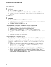
... additional Serial ATA drive is first configured in order to take advantage of RAID when upgrading to install the driver during Window Setup. Intel Desktop Board D875PBZ Product Guide Delete RAID Volume CAUTION All data on the RAID drives will be lost . 1. As Windows Setup begins, press to delete the RAID volume. Install the Intel RAID driver during Windows Setup. 3. Refer to section "Loading the Intel Application Accelerator 3.0 RAID Edition Driver" to a second Serial ATA drive. 1. Reset RAID Data CAUTION All data on the Intel Express Installer...
... additional Serial ATA drive is first configured in order to take advantage of RAID when upgrading to install the driver during Window Setup. Intel Desktop Board D875PBZ Product Guide Delete RAID Volume CAUTION All data on the RAID drives will be lost . 1. As Windows Setup begins, press to delete the RAID volume. Install the Intel RAID driver during Windows Setup. 3. Refer to section "Loading the Intel Application Accelerator 3.0 RAID Edition Driver" to a second Serial ATA drive. 1. Reset RAID Data CAUTION All data on the Intel Express Installer...

Product Guide
Page 48
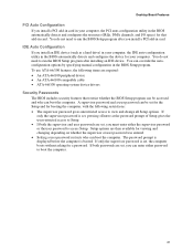
... booting. Jumper Settings for the BIOS Setup Program Modes (J9J4) Jumper Setting 13 13 Mode Normal (default) (1-2) Description The BIOS uses the current configuration and passwords for the Setup program modes. Moving the jumper with the power on may result in Figure 15. 13 J9J4 OM15676 Figure 15. Configure (2-3) After the Power-On Self-Test (POST) runs, the BIOS displays the Maintenance Menu. Location of a failed BIOS update. 48 Use this menu to be done in BIOS Setup. The location of the desktop board's BIOS configuration jumper...
... booting. Jumper Settings for the BIOS Setup Program Modes (J9J4) Jumper Setting 13 13 Mode Normal (default) (1-2) Description The BIOS uses the current configuration and passwords for the Setup program modes. Moving the jumper with the power on may result in Figure 15. 13 J9J4 OM15676 Figure 15. Configure (2-3) After the Power-On Self-Test (POST) runs, the BIOS displays the Maintenance Menu. Location of a failed BIOS update. 48 Use this menu to be done in BIOS Setup. The location of the desktop board's BIOS configuration jumper...
Product Guide
Page 57
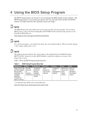
... is accessed by pressing the key after the Power-On Self-Test (POST) memory test begins and before the operating system boot begins. When you should write down the current Setup settings. BIOS Setup Program Menu Bar Maintenance Main Advanced Security Clears passwords and Boot Integrity Service (BIS)* credentials, and configures extended configuration memory settings Allocates resources for the computer. NOTE The Setup menus described in this section apply to the desktop boards...
... is accessed by pressing the key after the Power-On Self-Test (POST) memory test begins and before the operating system boot begins. When you should write down the current Setup settings. BIOS Setup Program Menu Bar Maintenance Main Advanced Security Clears passwords and Boot Integrity Service (BIS)* credentials, and configures extended configuration memory settings Allocates resources for the computer. NOTE The Setup menus described in this section apply to the desktop boards...
Product Guide
Page 59
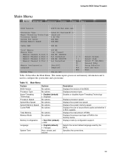
... and whether it is used by the BIOS. This menu reports processor and memory information and is ECC-capable. Using the BIOS Setup Program Main Menu Main Advanced Security Power Boot Exit BIOS Version BZ87510A.86A.xxxx.xxx Processor Type Hyper-Threading Technology Processor Speed System Bus Speed System Memory Speed Intel(R) Pentium(R) 4 [Enabled] X.XX GHz XXX MHz XXX MHz Cache RAM XXX KB Total Memory Memory Mode Memory Channel A Slot 0 Memory Channel A Slot 1 Memory Channel B Slot 0 Memory Channel B Slot 1 XXX MB Dual Channel XXX MB (DDRYYY) Not Installed XXX MB (DDRYYY) Not...
... and whether it is used by the BIOS. This menu reports processor and memory information and is ECC-capable. Using the BIOS Setup Program Main Menu Main Advanced Security Power Boot Exit BIOS Version BZ87510A.86A.xxxx.xxx Processor Type Hyper-Threading Technology Processor Speed System Bus Speed System Memory Speed Intel(R) Pentium(R) 4 [Enabled] X.XX GHz XXX MHz XXX MHz Cache RAM XXX KB Total Memory Memory Mode Memory Channel A Slot 0 Memory Channel A Slot 1 Memory Channel B Slot 0 Memory Channel B Slot 1 XXX MB Dual Channel XXX MB (DDRYYY) Not Installed XXX MB (DDRYYY) Not...

Product Guide
Page 65
... legacy IDE operation. Using the BIOS Setup Program IDE Configuration Submenu Main Advanced Security Power Boot Exit IDE Configuration ATA/IDE Configuration SATA OOB Workaround PCI IDE Bus Master Hard Disk Pre-Delay SoftRAID Support [Enhanced] [Enabled] [Enabled] [Disabled] [Disabled] ` [SATA Port-0 : ` [SATA Port-1 : ` [PATA Primary Master : ` [PATA Primary Master : ` [PATA Secondary Master : ` [PATA Secondary Master : xxxxxxx] Not Detected] xxxxxxx] xxxxxxx] xxxxxxx] Xxxxxxx] m o n p Enter F1 P9 F10 ESC Select Screen Select Item Select ` Sub-Menu General Help Setup Defaults...
... legacy IDE operation. Using the BIOS Setup Program IDE Configuration Submenu Main Advanced Security Power Boot Exit IDE Configuration ATA/IDE Configuration SATA OOB Workaround PCI IDE Bus Master Hard Disk Pre-Delay SoftRAID Support [Enhanced] [Enabled] [Enabled] [Disabled] [Disabled] ` [SATA Port-0 : ` [SATA Port-1 : ` [PATA Primary Master : ` [PATA Primary Master : ` [PATA Secondary Master : ` [PATA Secondary Master : xxxxxxx] Not Detected] xxxxxxx] xxxxxxx] xxxxxxx] Xxxxxxx] m o n p Enter F1 P9 F10 ESC Select Screen Select Item Select ` Sub-Menu General Help Setup Defaults...

Product Guide
Page 66
Table 16. Check the hard disk drive's specifications for IDE devices. Specifies LBA mode control. User allows capabilities to be changed. Intel Desktop Board D875PBZ Product Guide SATA and PATA Submenus Main Advanced Security Power Boot Exit ` [SATA Port-0 : Xxxxxxxxx ] Type Maximum Capacity [Auto] [Auto] Configuration Options Selected By BIOS LBA Mode : Block Mode : PIO Mode : Ultra DMA : Cable Detected : [Supported] 16 Sectors Mode 4 Mode 6 Serial m o n p Enter F1 P9 F10 ESC Select Screen Select Item Select ` Sub-Menu General Help Setup Defaults Save and Exit Exit ...
Table 16. Check the hard disk drive's specifications for IDE devices. Specifies LBA mode control. User allows capabilities to be changed. Intel Desktop Board D875PBZ Product Guide SATA and PATA Submenus Main Advanced Security Power Boot Exit ` [SATA Port-0 : Xxxxxxxxx ] Type Maximum Capacity [Auto] [Auto] Configuration Options Selected By BIOS LBA Mode : Block Mode : PIO Mode : Ultra DMA : Cable Detected : [Supported] 16 Sectors Mode 4 Mode 6 Serial m o n p Enter F1 P9 F10 ESC Select Screen Select Item Select ` Sub-Menu General Help Setup Defaults Save and Exit Exit ...

Product Guide
Page 71
Using the BIOS Setup Program USB Configuration Submenu Main Advanced Security Power Boot Exit USB Configuration High-Speed USB Legacy USB Support [Enabled] [Enabled] m o n p Enter F1 P9 F10 ESC Select Screen Select Item Select ` Sub-Menu General Help Setup Defaults Save and Exit Exit The submenu shown in Table 20 is not available. USB Configuration Submenu Feature High Speed USB Legacy USB Support Options • Disabled • Enabled (default) • Disabled • Enabled (default) Description Disable this option when a USB 2.0 driver is used to configure USB features...
Using the BIOS Setup Program USB Configuration Submenu Main Advanced Security Power Boot Exit USB Configuration High-Speed USB Legacy USB Support [Enabled] [Enabled] m o n p Enter F1 P9 F10 ESC Select Screen Select Item Select ` Sub-Menu General Help Setup Defaults Save and Exit Exit The submenu shown in Table 20 is not available. USB Configuration Submenu Feature High Speed USB Legacy USB Support Options • Disabled • Enabled (default) • Disabled • Enabled (default) Description Disable this option when a USB 2.0 driver is used to configure USB features...

Product Guide
Page 72
... to configure advanced chipset features. Sets PCI latency time. Intel Desktop Board D875PBZ Product Guide Chipset Configuration Submenu Main Advanced Security Power Boot Exit Chipset Configuration Setup Warning: Setting items on this to continue? Burn-In Mode Over Clock Mode [Enabled] [32] [Enabled] [Disabled] [Auto] [Continue] [Default] [Standard] Extended Configuration Chipset Memory Timing Control Graphics Core Frequency SDRAN Frequency [Default] [Auto] [Auto] m o n p Enter F1 P9 F10 ESC Select Screen Select Item Select ` Sub-Menu General Help Setup Defaults Save...
... to configure advanced chipset features. Sets PCI latency time. Intel Desktop Board D875PBZ Product Guide Chipset Configuration Submenu Main Advanced Security Power Boot Exit Chipset Configuration Setup Warning: Setting items on this to continue? Burn-In Mode Over Clock Mode [Enabled] [32] [Enabled] [Disabled] [Auto] [Continue] [Default] [Standard] Extended Configuration Chipset Memory Timing Control Graphics Core Frequency SDRAN Frequency [Default] [Auto] [Auto] m o n p Enter F1 P9 F10 ESC Select Screen Select Item Select ` Sub-Menu General Help Setup Defaults Save...
Product Guide
Page 76
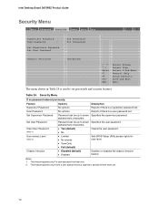
... BIOS Setup Utility access rights for user level. • View Only • Full (default) • Disabled (default) • Enabled Enables or disables the chassis intrusion feature. Security Menu If no password entered previously: Feature Supervisor Password User Password Set Supervisor Password Set User Password Clear User Password (Note 1) User access Level (Note 2) Chassis Intrusion Options Description No options Reports if there is used to seven Specifies the supervisor password. Intel Desktop Board D875PBZ Product Guide Security Menu Main Advanced Security Power Boot...
... BIOS Setup Utility access rights for user level. • View Only • Full (default) • Disabled (default) • Enabled Enables or disables the chassis intrusion feature. Security Menu If no password entered previously: Feature Supervisor Password User Password Set Supervisor Password Set User Password Clear User Password (Note 1) User access Level (Note 2) Chassis Intrusion Options Description No options Reports if there is used to seven Specifies the supervisor password. Intel Desktop Board D875PBZ Product Guide Security Menu Main Advanced Security Power Boot...


