
D865PCK Technical Product Specification
Page 6
... PCI IDE Support 64 3.4 System Management BIOS (SMBIOS 65 3.5 Legacy USB Support...65 3.6 BIOS Updates ...66 3.6.1 Language Support 66 3.6.2 Custom Splash Screen 66 3.7 Boot Options ...67 3.7.1 CD-ROM Boot 67 3.7.2 Network Boot 67 3.7.3 Booting Without Attached Devices 67 3.7.4 Changing the Default Boot Device During POST 67 3.8 Fast Booting Systems with Intel® Rapid BIOS Boot 68 3.8.1 Peripheral Selection and Configuration 68 3.8.2 Intel Rapid BIOS Boot 68 3.9 BIOS Security Features 69 4 Error Messages and Beep Codes 4.1 Speaker ...71 4.2 BIOS Beep Codes...71 4.3 BIOS Error...
... PCI IDE Support 64 3.4 System Management BIOS (SMBIOS 65 3.5 Legacy USB Support...65 3.6 BIOS Updates ...66 3.6.1 Language Support 66 3.6.2 Custom Splash Screen 66 3.7 Boot Options ...67 3.7.1 CD-ROM Boot 67 3.7.2 Network Boot 67 3.7.3 Booting Without Attached Devices 67 3.7.4 Changing the Default Boot Device During POST 67 3.8 Fast Booting Systems with Intel® Rapid BIOS Boot 68 3.8.1 Peripheral Selection and Configuration 68 3.8.2 Intel Rapid BIOS Boot 68 3.9 BIOS Security Features 69 4 Error Messages and Beep Codes 4.1 Speaker ...71 4.2 BIOS Beep Codes...71 4.3 BIOS Error...
D865PCK Technical Product Specification
Page 7
...Front Panel Power/Sleep/Message-Waiting LED Connector 47 24. Front Panel Audio Connector/Jumper Block 51 28. LAN Connector LED Locations 24 8. LAN Connector LED States 24 6. Front Chassis Fan Connector 44 22. BIOS Setup Configuration Jumper Settings 51 vii Contents Figures 1. Desktop Board D865PCK Components 11 2. Block Diagram...12 3. Memory Channel Configuration 16 4. Example of Dual Channel Configuration with Dynamic Mode 17 6. Example of Dual/Single Channel Configuration with/without Dynamic Mode 18 7. Back Panel Connectors 38 9. Audio Connectors...40...
...Front Panel Power/Sleep/Message-Waiting LED Connector 47 24. Front Panel Audio Connector/Jumper Block 51 28. LAN Connector LED Locations 24 8. LAN Connector LED States 24 6. Front Chassis Fan Connector 44 22. BIOS Setup Configuration Jumper Settings 51 vii Contents Figures 1. Desktop Board D865PCK Components 11 2. Block Diagram...12 3. Memory Channel Configuration 16 4. Example of Dual Channel Configuration with Dynamic Mode 17 6. Example of Dual/Single Channel Configuration with/without Dynamic Mode 18 7. Back Panel Connectors 38 9. Audio Connectors...40...
D865PCK Technical Product Specification
Page 11
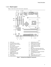
... processor socket I Processor fan connector J Intel 82865P MCH K DIMM Channel A socket L DIMM Channel B socket M I/O controller N Power connector OM17040 O Diskette drive connector P Parallel ATE IDE connectors Q Front chassis fan connector R Chassis intrusion connector S 8 Mbit Firmware Hub (FWH) T Speaker U BIOS Setup configuration jumper block V Auxiliary front panel power LED connector W Front panel connector X Intel 82801EB I/O Controller Hub (ICH5) Y Front panel USB connector Z Battery AA PCI bus add-in card connectors BB ATAPI CD-ROM connector Figure 1. 1.1.2 Board Layout Figure...
... processor socket I Processor fan connector J Intel 82865P MCH K DIMM Channel A socket L DIMM Channel B socket M I/O controller N Power connector OM17040 O Diskette drive connector P Parallel ATE IDE connectors Q Front chassis fan connector R Chassis intrusion connector S 8 Mbit Firmware Hub (FWH) T Speaker U BIOS Setup configuration jumper block V Auxiliary front panel power LED connector W Front panel connector X Intel 82801EB I/O Controller Hub (ICH5) Y Front panel USB connector Z Battery AA PCI bus add-in card connectors BB ATAPI CD-ROM connector Figure 1. 1.1.2 Board Layout Figure...
D865PCK Technical Product Specification
Page 20
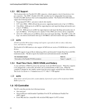
... defaults, if previously saved, will be independently enabled. The drive reports the transfer rate and translation mode to Figure 11, page 45 1.5.4 Real-Time Clock, CMOS SRAM, and Battery A coin-cell battery (CR2032) powers the real-time clock and CMOS memory. When the computer is not plugged into CMOS RAM at 25 ºC with serialized IRQ support for PCI systems 20 The ICH5's Parallel ATA IDE controller has two independent bus...
... defaults, if previously saved, will be independently enabled. The drive reports the transfer rate and translation mode to Figure 11, page 45 1.5.4 Real-Time Clock, CMOS SRAM, and Battery A coin-cell battery (CR2032) powers the real-time clock and CMOS memory. When the computer is not plugged into CMOS RAM at 25 ºC with serialized IRQ support for PCI systems 20 The ICH5's Parallel ATA IDE controller has two independent bus...
D865PCK Technical Product Specification
Page 37
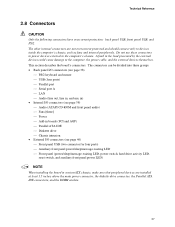
... CD-ROM and front panel audio) ⎯ Fans [three] ⎯ Power ⎯ Add-in boards (PCI and AGP) ⎯ Parallel ATA IDE ⎯ Diskette drive ⎯ Chassis intrusion • External I/O connectors (see page 46) ⎯ Front panel USB (two connector for four ports) ⎯ Auxiliary front panel power/sleep/message-waiting LED ⎯ Front panel (power/sleep/message-waiting LED, power switch, hard drive activity LED, reset switch, and auxiliary front panel power LED) NOTE When installing the board in the load presented by the external devices...
... CD-ROM and front panel audio) ⎯ Fans [three] ⎯ Power ⎯ Add-in boards (PCI and AGP) ⎯ Parallel ATA IDE ⎯ Diskette drive ⎯ Chassis intrusion • External I/O connectors (see page 46) ⎯ Front panel USB (two connector for four ports) ⎯ Auxiliary front panel power/sleep/message-waiting LED ⎯ Front panel (power/sleep/message-waiting LED, power switch, hard drive activity LED, reset switch, and auxiliary front panel power LED) NOTE When installing the board in the load presented by the external devices...
D865PCK Technical Product Specification
Page 63
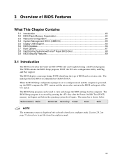
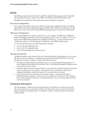
...BIOS Setup program, POST, the PCI auto-configuration utility, and Plug and Play support. Maintenance Main Advanced Security Power Boot Exit NOTE The maintenance menu is displayed only when the board is shown below. When the BIOS Setup configuration jumper is set to view and change the BIOS settings for the computer. The BIOS displays a message during POST identifying the type of BIOS Features What This Chapter Contains 3.1 Introduction ...63 3.2 BIOS Flash Memory Organization 64 3.3 Resource Configuration 64 3.4 System Management BIOS (SMBIOS 65 3.5 Legacy USB Support...
...BIOS Setup program, POST, the PCI auto-configuration utility, and Plug and Play support. Maintenance Main Advanced Security Power Boot Exit NOTE The maintenance menu is displayed only when the board is shown below. When the BIOS Setup configuration jumper is set to view and change the BIOS settings for the computer. The BIOS displays a message during POST identifying the type of BIOS Features What This Chapter Contains 3.1 Introduction ...63 3.2 BIOS Flash Memory Organization 64 3.3 Resource Configuration 64 3.4 System Management BIOS (SMBIOS 65 3.5 Legacy USB Support...
D865PCK Technical Product Specification
Page 64
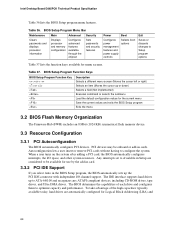
BIOS Setup Program Menu Bar Maintenance Main Advanced Security Clears passwords and displays processor information Displays processor and memory configuration Configures advanced features available through the chipset Sets passwords and security features Power Boot Configures power management features and power supply controls Selects boot options Exit Saves or discards changes to Available in Setup are automatically configured for use by the add-in card. 3.3.2 PCI IDE Support If you select Auto in cards. PCI devices may be available for Logical Block Addressing (LBA) and ...
BIOS Setup Program Menu Bar Maintenance Main Advanced Security Clears passwords and displays processor information Displays processor and memory configuration Configures advanced features available through the chipset Sets passwords and security features Power Boot Configures power management features and power supply controls Selects boot options Exit Saves or discards changes to Available in Setup are automatically configured for use by the add-in card. 3.3.2 PCI IDE Support If you select Auto in cards. PCI devices may be available for Logical Block Addressing (LBA) and ...
D865PCK Technical Product Specification
Page 65
... use a USB keyboard to be used to access the BIOS Setup program, and to install an operating system that supports USB. The BIOS enables applications such as Windows NT*, require an additional interface for managing computers in the BIOS Setup program. Legacy USB support operates as a slave to an ATAPI CD-ROM drive. 3.4 System Management BIOS (SMBIOS) SMBIOS is set to the computer, legacy support is enabled by specifying manual configuration in a managed network. Overview of BIOS Features to use...
... use a USB keyboard to be used to access the BIOS Setup program, and to install an operating system that supports USB. The BIOS enables applications such as Windows NT*, require an additional interface for managing computers in the BIOS Setup program. Legacy USB support operates as a slave to an ATAPI CD-ROM drive. 3.4 System Management BIOS (SMBIOS) SMBIOS is set to the computer, legacy support is enabled by specifying manual configuration in a managed network. Overview of BIOS Features to use...
D865PCK Technical Product Specification
Page 68
... monitors. In the Boot Menu: • Set the hard disk drive as logo displays, screen repaints, or mode changes in adapter features, such as the first boot device. If this condition should occur, it will not be seen. Some monitors initialize and communicate with the BIOS more quickly. 3.8.2 Intel Rapid BIOS Boot Use of the BIOS Setup program). 68 This feature bypasses memory count and the search for a diskette drive. This can influence POST...
... monitors. In the Boot Menu: • Set the hard disk drive as logo displays, screen repaints, or mode changes in adapter features, such as the first boot device. If this condition should occur, it will not be seen. Some monitors initialize and communicate with the BIOS more quickly. 3.8.2 Intel Rapid BIOS Boot Use of the BIOS Setup program). 68 This feature bypasses memory count and the search for a diskette drive. This can influence POST...
D865PCK Technical Product Specification
Page 72
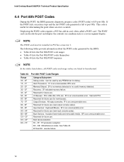
...: Miscellaneous codes. The POST card can decode the port and display the contents on a medium such as a seven-segment display. Memory/Chipset: 2F is an unrecoverable error. Boot Devices: Includes fixed media and removable media. DF E0 - I /O port 80h. Reserved for future use . BF is an unrecoverable error. Boot device selection. EF boot/S3: resume failure. 72 Intel Desktop Board D865PCK Technical Product Specification 4.4 Port 80h POST Codes During the POST, the BIOS generates diagnostic progress codes (POST-codes) to I /O Busses: PCI, USB, ISA...
...: Miscellaneous codes. The POST card can decode the port and display the contents on a medium such as a seven-segment display. Memory/Chipset: 2F is an unrecoverable error. Boot Devices: Includes fixed media and removable media. DF E0 - I /O port 80h. Reserved for future use . BF is an unrecoverable error. Boot device selection. EF boot/S3: resume failure. 72 Intel Desktop Board D865PCK Technical Product Specification 4.4 Port 80h POST Codes During the POST, the BIOS generates diagnostic progress codes (POST-codes) to I /O Busses: PCI, USB, ISA...
D865PCK Technical Product Specification
Page 73
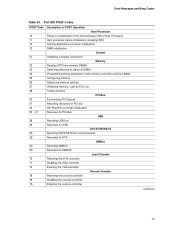
... memory settings Initializing memory, such as ECC init Testing memory PCI Bus Enumerating PCI busses Allocating resources to PCI bus Hot Plug PCI controller initialization Reserved for PCI Bus USB Resetting USB bus Reserved for USB ATA/ATAPI/SATA Resetting PATA/SATA bus and all devices Reserved for ATA SMBus Resetting SMBUS Reserved for SMBUS Local Console Resetting the VGA controller Disabling the VGA controller Enabling the VGA controller Remote Console Resetting the console controller Disabling the console controller Enabling the console controller continued 73 Error Messages and Beep...
... memory settings Initializing memory, such as ECC init Testing memory PCI Bus Enumerating PCI busses Allocating resources to PCI bus Hot Plug PCI controller initialization Reserved for PCI Bus USB Resetting USB bus Reserved for USB ATA/ATAPI/SATA Resetting PATA/SATA bus and all devices Reserved for ATA SMBus Resetting SMBUS Reserved for SMBUS Local Console Resetting the VGA controller Disabling the VGA controller Enabling the VGA controller Remote Console Resetting the console controller Disabling the console controller Enabling the console controller continued 73 Error Messages and Beep...
English Product Guide
Page 6
...30 Connecting the IDE Cable...31 Connecting Internal Headers 32 Connecting the Front Panel Header 33 Connecting the USB 2.0 Header 33 Installing a Front Panel Audio Solution 34 Connecting Hardware Control and Power Cables 35 Connecting the Chassis Intrusion Cable 36 Connecting Fans ...36 Connecting Power Supply Cables 36 Add-In Card and Peripheral Interface Connectors 37 Setting the BIOS Configuration Jumper Block 38 Clearing BIOS Passwords...39 Back Panel Connectors...40 Replacing the Battery...41 3 Updating the BIOS Updating the BIOS with the Intel® Express BIOS Update Utility...
...30 Connecting the IDE Cable...31 Connecting Internal Headers 32 Connecting the Front Panel Header 33 Connecting the USB 2.0 Header 33 Installing a Front Panel Audio Solution 34 Connecting Hardware Control and Power Cables 35 Connecting the Chassis Intrusion Cable 36 Connecting Fans ...36 Connecting Power Supply Cables 36 Add-In Card and Peripheral Interface Connectors 37 Setting the BIOS Configuration Jumper Block 38 Clearing BIOS Passwords...39 Back Panel Connectors...40 Replacing the Battery...41 3 Updating the BIOS Updating the BIOS with the Intel® Express BIOS Update Utility...
English Product Guide
Page 7
Installing the I/O Shield 24 4. Location of the BIOS Configuration Jumper Block 38 14. Feature Summary...9 2. USB 2.0 Header ...33 6. BIOS Error Messages...52 10. LAN Connector LED Locations 16 3. Connecting the Processor Fan Heat Sink Cable to the Processor Fan Connector ........ 27 7. PCI Bus Add-in Card and Peripheral Interface Connectors 37 13. Safety Regulations ...55 11. Desktop Board Components 12 3. Desktop Board D865PCK Components 11 2. Removing the AGP Card 30 9. RJ-45 10/100 Ethernet LAN Connector LEDs 16 4. Connecting the IDE Cable ...
Installing the I/O Shield 24 4. Location of the BIOS Configuration Jumper Block 38 14. Feature Summary...9 2. USB 2.0 Header ...33 6. BIOS Error Messages...52 10. LAN Connector LED Locations 16 3. Connecting the Processor Fan Heat Sink Cable to the Processor Fan Connector ........ 27 7. PCI Bus Add-in Card and Peripheral Interface Connectors 37 13. Safety Regulations ...55 11. Desktop Board Components 12 3. Desktop Board D865PCK Components 11 2. Removing the AGP Card 30 9. RJ-45 10/100 Ethernet LAN Connector LEDs 16 4. Connecting the IDE Cable ...
English Product Guide
Page 9
...; One serial port • PS/2* keyboard and mouse ports Three PCI bus add-in card connectors (SMBus routed to PCI bus 2) • Intel® Platform Innovation Framework • Intel® Rapid BIOS Boot • Intel® Express BIOS Update • Support for SMBIOS continued 9 Table 1. Two ports routed to the internal USB front panel header • Two IDE interfaces with Accelerated Hub Architecture (AHA) bus • Intel® 82801EB I/O Controller Hub (ICH5) • 8 Mbit Firmware Hub (FWH) • Intel 865P chipset...
...; One serial port • PS/2* keyboard and mouse ports Three PCI bus add-in card connectors (SMBus routed to PCI bus 2) • Intel® Platform Innovation Framework • Intel® Rapid BIOS Boot • Intel® Express BIOS Update • Support for SMBIOS continued 9 Table 1. Two ports routed to the internal USB front panel header • Two IDE interfaces with Accelerated Hub Architecture (AHA) bus • Intel® 82801EB I/O Controller Hub (ICH5) • 8 Mbit Firmware Hub (FWH) • Intel 865P chipset...

English Product Guide
Page 12
...Diskette drive connector Primary IDE connector Secondary IDE connector Front chassis fan header Chassis intrusion header Speaker BIOS configuration jumper Alternate power/sleep LED header Front panel header Intel 82801EB (ICH5) USB 2.0 header Battery PCI bus add-in card connectors Related Links Go to the following links for the latest information about: • Intel Desktop Board D865PCK, http://www.intel.com/design/motherbd • Processors, http://support.intel.com/support/motherboards/desktop • Audio software and utilities, http://www.intel.com/design/motherbd • LAN software...
...Diskette drive connector Primary IDE connector Secondary IDE connector Front chassis fan header Chassis intrusion header Speaker BIOS configuration jumper Alternate power/sleep LED header Front panel header Intel 82801EB (ICH5) USB 2.0 header Battery PCI bus add-in card connectors Related Links Go to the following links for the latest information about: • Intel Desktop Board D865PCK, http://www.intel.com/design/motherbd • Processors, http://support.intel.com/support/motherboards/desktop • Audio software and utilities, http://www.intel.com/design/motherbd • LAN software...
English Product Guide
Page 18
... resources (IRQs, DMA channels, and I/O space) for a password. PCI Auto Configuration If you install an IDE device (such as a hard drive) in your computer, the IDE auto-configuration utility in the BIOS automatically detects and configures the device for your computer, the PCI auto-configuration utility in your computer. Intel Desktop Board D865PCK Product Guide BIOS The BIOS provides the Power-On Self-Test (POST), the BIOS Setup program, the PCI and IDE auto-configuration utilities, and the video BIOS. The BIOS can boot the computer. To use ATA-66/100 features...
... resources (IRQs, DMA channels, and I/O space) for a password. PCI Auto Configuration If you install an IDE device (such as a hard drive) in your computer, the IDE auto-configuration utility in the BIOS automatically detects and configures the device for your computer, the PCI auto-configuration utility in your computer. Intel Desktop Board D865PCK Product Guide BIOS The BIOS provides the Power-On Self-Test (POST), the BIOS Setup program, the PCI and IDE auto-configuration utilities, and the video BIOS. The BIOS can boot the computer. To use ATA-66/100 features...
English Product Guide
Page 34
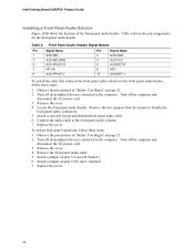
... R channel). 6. Intel Desktop Board D865PCK Product Guide Installing a Front Panel Audio Solution Figure 10-B shows the location of the front panel audio header. Locate the front panel audio header. Install a correctly keyed and shielded front panel audio cable. 6. Remove the two jumpers from the header to the front panel audio solution. 7. Turn off all peripheral devices connected to the computer. Install a jumper on page 21. 2. Observe the precautions in "Before You Begin" on pins 9-10 (rear L channel). 7. Turn off the computer and disconnect the AC power...
... R channel). 6. Intel Desktop Board D865PCK Product Guide Installing a Front Panel Audio Solution Figure 10-B shows the location of the front panel audio header. Locate the front panel audio header. Install a correctly keyed and shielded front panel audio cable. 6. Remove the two jumpers from the header to the front panel audio solution. 7. Turn off all peripheral devices connected to the computer. Install a jumper on page 21. 2. Observe the precautions in "Before You Begin" on pins 9-10 (rear L channel). 7. Turn off the computer and disconnect the AC power...
English Product Guide
Page 38
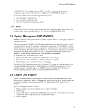
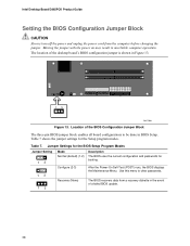
... changing the jumper. Use this menu to be done in unreliable computer operation. The location of a failed BIOS update. 38 Intel Desktop Board D865PCK Product Guide Setting the BIOS Configuration Jumper Block CAUTION Always turn off the power and unplug the power cord from a recovery diskette in the event of the desktop board's BIOS configuration jumper is shown in Figure 13. 13 OM17409 Figure 13. Table 7 shows the jumper settings for booting. Jumper Settings for the BIOS Setup Program Modes Jumper Setting 1 3 1 3 1 3 Mode Normal (default) (1-2) Description The BIOS uses...
... changing the jumper. Use this menu to be done in unreliable computer operation. The location of a failed BIOS update. 38 Intel Desktop Board D865PCK Product Guide Setting the BIOS Configuration Jumper Block CAUTION Always turn off the power and unplug the power cord from a recovery diskette in the event of the desktop board's BIOS configuration jumper is shown in Figure 13. 13 OM17409 Figure 13. Table 7 shows the jumper settings for booting. Jumper Settings for the BIOS Setup Program Modes Jumper Setting 1 3 1 3 1 3 Mode Normal (default) (1-2) Description The BIOS uses...
English Product Guide
Page 39
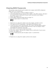
... to normal mode. 1. Disconnect the computer's power cord from the AC power source (wall outlet or power adapter). 3. The computer starts the Setup program. Select Yes and press . Replace the cover, plug in the computer, turn on the computer. 39 Find the BIOS configuration jumper block (see Figure 13). 5. Remove the computer cover. 12. Remove the computer cover. 4. Turn off the computer. Installing and Replacing Desktop Board Components Clearing BIOS Passwords This...
... to normal mode. 1. Disconnect the computer's power cord from the AC power source (wall outlet or power adapter). 3. The computer starts the Setup program. Select Yes and press . Replace the cover, plug in the computer, turn on the computer. 39 Find the BIOS configuration jumper block (see Figure 13). 5. Remove the computer cover. 12. Remove the computer cover. 4. Turn off the computer. Installing and Replacing Desktop Board Components Clearing BIOS Passwords This...
English Product Guide
Page 52
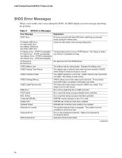
... Slave Drive - A: Drive Error B: Drive Error No response from corresponding drive. FDC Failure Error occurred trying to reset values. Pri Master HDD Error Pri Slave HDD Error Sec Master HDD Error Sec Slave HDD Error Could not read /write test of DMA controller. Run Setup to access diskette drive controller. CMOS Checksum Bad The CMOS checksum is different than what has been stored in CMOS. Intel Desktop Board D865PCK Product Guide BIOS Error Messages When a recoverable error occurs during the memory test. CMOS Display Type Wrong The display type...
... Slave Drive - A: Drive Error B: Drive Error No response from corresponding drive. FDC Failure Error occurred trying to reset values. Pri Master HDD Error Pri Slave HDD Error Sec Master HDD Error Sec Slave HDD Error Could not read /write test of DMA controller. Run Setup to access diskette drive controller. CMOS Checksum Bad The CMOS checksum is different than what has been stored in CMOS. Intel Desktop Board D865PCK Product Guide BIOS Error Messages When a recoverable error occurs during the memory test. CMOS Display Type Wrong The display type...


