

Product Specification
Page 8
...Front Panel Audio Connector 47 18. Chassis Intrusion Connector 50 24. Auxiliary Front Panel Power/Sleep/Message-Waiting LED Connector 53 25. Power and Hardware Control Connectors 48 11. Characteristics of Dual Channel Configuration with /without Dynamic Mode 24 7. Wake-up Devices and Events 32 10. Rear Chassis Fan Connector 49 19. Intel Desktop Board D865PCD Technical Product Specification Figures 1. Block Diagram ...14 3. Memory Channel Configuration 22 4. Example of Pressing the Power Switch 31 8. LAN Connector LED Locations 30 8. Audio Connectors ...46...
...Front Panel Audio Connector 47 18. Chassis Intrusion Connector 50 24. Auxiliary Front Panel Power/Sleep/Message-Waiting LED Connector 53 25. Power and Hardware Control Connectors 48 11. Characteristics of Dual Channel Configuration with /without Dynamic Mode 24 7. Wake-up Devices and Events 32 10. Rear Chassis Fan Connector 49 19. Intel Desktop Board D865PCD Technical Product Specification Figures 1. Block Diagram ...14 3. Memory Channel Configuration 22 4. Example of Pressing the Power Switch 31 8. LAN Connector LED Locations 30 8. Audio Connectors ...46...
Product Specification
Page 9
... CD-ROM Drives Submenu 99 62. Exit Menu ...99 63. Front Panel Audio Connector/Jumper Block 57 29. BIOS Setup Configuration Jumper Settings 57 30. DC Loading Characteristics 60 31. Safety Regulations ...65 35. Video Configuration Submenu 90 52. Hard Disk Drives Submenu 98 60. Bus Initialization Checkpoints 107 68. Beep Codes...109 ix Contents 26. States for a One-Color Power LED 54 27. Power Menu ...95 56. Main Menu...79 43. Advanced Menu...80 44. Upper Nibble High...
... CD-ROM Drives Submenu 99 62. Exit Menu ...99 63. Front Panel Audio Connector/Jumper Block 57 29. BIOS Setup Configuration Jumper Settings 57 30. DC Loading Characteristics 60 31. Safety Regulations ...65 35. Video Configuration Submenu 90 52. Hard Disk Drives Submenu 98 60. Bus Initialization Checkpoints 107 68. Beep Codes...109 ix Contents 26. States for a One-Color Power LED 54 27. Power Menu ...95 56. Main Menu...79 43. Advanced Menu...80 44. Upper Nibble High...
Product Specification
Page 26
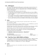
... the Parallel ATA IDE interfaces. floppy disk drive) • ARMD-HDD (ATAPI removable media device - Intel Desktop Board D865PCD Technical Product Specification 1.6.3 IDE Support The board provides two Parallel ATA IDE connectors, which support a total of the Parallel ATA IDE connectors Refer to Figure 11, page 51 1.6.4 Real-Time Clock, CMOS SRAM, and Battery A coin-cell battery (CR2032) powers the real-time clock and CMOS memory. The BIOS supports Logical Block Addressing (LBA) and Extended Cylinder Head Sector (ECHS) translation modes.
... the Parallel ATA IDE interfaces. floppy disk drive) • ARMD-HDD (ATAPI removable media device - Intel Desktop Board D865PCD Technical Product Specification 1.6.3 IDE Support The board provides two Parallel ATA IDE connectors, which support a total of the Parallel ATA IDE connectors Refer to Figure 11, page 51 1.6.4 Real-Time Clock, CMOS SRAM, and Battery A coin-cell battery (CR2032) powers the real-time clock and CMOS memory. The BIOS supports Logical Block Addressing (LBA) and Extended Cylinder Head Sector (ECHS) translation modes.
Product Specification
Page 43
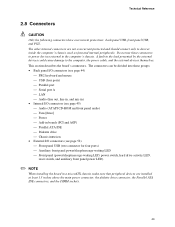
...-ROM and front panel audio) Fans [three] Power Add-in boards (PCI and AGP) Parallel ATA IDE Diskette drive Chassis intrusion • External I/O connectors (see page 52) Front panel USB (two connector for four ports) Auxiliary front panel power/sleep/message-waiting LED Front panel (power/sleep/message-waiting LED, power switch, hard drive activity LED, reset switch, and auxiliary front panel power LED) ✏ NOTE When installing the board in the load presented by the external devices...
...-ROM and front panel audio) Fans [three] Power Add-in boards (PCI and AGP) Parallel ATA IDE Diskette drive Chassis intrusion • External I/O connectors (see page 52) Front panel USB (two connector for four ports) Auxiliary front panel power/sleep/message-waiting LED Front panel (power/sleep/message-waiting LED, power switch, hard drive activity LED, reset switch, and auxiliary front panel power LED) ✏ NOTE When installing the board in the load presented by the external devices...

Product Specification
Page 70
... use by the BIOS Refer to an ATAPI CD-ROM drive. 70 Intel Desktop Board D865PCD Technical Product Specification 3.3 Resource Configuration 3.3.1 PCI Autoconfiguration The BIOS can override the auto-configuration options by specifying manual configuration in the BIOS Setup program. The BIOS determines the capabilities of ATAPI). Any interrupts set to Available in Setup are considered to PIO Mode 3 or 4, depending on the same IDE cable as an ATAPI master device. You can automatically configure PCI devices. The IDE interface supports hard drives...
... use by the BIOS Refer to an ATAPI CD-ROM drive. 70 Intel Desktop Board D865PCD Technical Product Specification 3.3 Resource Configuration 3.3.1 PCI Autoconfiguration The BIOS can override the auto-configuration options by specifying manual configuration in the BIOS Setup program. The BIOS determines the capabilities of ATAPI). Any interrupts set to Available in Setup are considered to PIO Mode 3 or 4, depending on the same IDE cable as an ATAPI master device. You can automatically configure PCI devices. The IDE interface supports hard drives...

Product Specification
Page 77
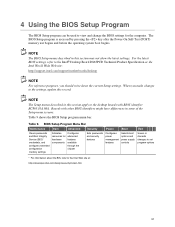
... Desktop Board in configure mode. however, the maintenance menu is displayed only when the Desktop Board is in configure mode. 77 BIOS Setup Program Menu Bar Maintenance Main Advanced Security Clears passwords and displays processor information Displays processor and memory configuration Configures advanced features available through the chipset Sets passwords and security features Power Boot Configures power management features and power supply controls Selects boot options Exit Saves or discards changes to view and change the BIOS settings for the computer. 4 BIOS Setup...
... Desktop Board in configure mode. however, the maintenance menu is displayed only when the Desktop Board is in configure mode. 77 BIOS Setup Program Menu Bar Maintenance Main Advanced Security Clears passwords and displays processor information Displays processor and memory configuration Configures advanced features available through the chipset Sets passwords and security features Power Boot Configures power management features and power supply controls Selects boot options Exit Saves or discards changes to view and change the BIOS settings for the computer. 4 BIOS Setup...

Product Specification
Page 78
...To access this menu in Table 41 is for menu screens. Table 41. Displays CPU's Microcode Update Revision. 78 Maintenance Menu Feature Options Clear All Passwords • Ok (default) • Cancel CPU Stepping Signature No options CPU Microcode Update Revision No options Description Clears the user and supervisor passwords. Setup only displays this menu, select Maintenance on page 57 for configure mode setting information. Table 40. Intel Desktop Board D865PCD Technical Product Specification Table 40 lists the function keys available for clearing Setup passwords and...
...To access this menu in Table 41 is for menu screens. Table 41. Displays CPU's Microcode Update Revision. 78 Maintenance Menu Feature Options Clear All Passwords • Ok (default) • Cancel CPU Stepping Signature No options CPU Microcode Update Revision No options Description Clears the user and supervisor passwords. Setup only displays this menu, select Maintenance on page 57 for configure mode setting information. Table 40. Intel Desktop Board D865PCD Technical Product Specification Table 40 lists the function keys available for clearing Setup passwords and...
Product Specification
Page 85
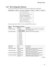
...disk drive pre-delay. Reports type of DMA for hard drive BIOS INT13 reads and writes. BIOS Setup Program 4.4.4 Drive Configuration Submenu To access this submenu, select Advanced on Parallel ATA (PATA) IDE primary slave interface. Maintenance Main Advanced Security Power PCI Configuration Boot Configuration Peripheral Configuration Drive Configuration Floppy Configuration Event Log Configuration Video Configuration USB Configuration Chipset Configuration Boot Exit The menu represented in Table 47 is used to display sub-menu Description Enables/disables the use of connected device...
...disk drive pre-delay. Reports type of DMA for hard drive BIOS INT13 reads and writes. BIOS Setup Program 4.4.4 Drive Configuration Submenu To access this submenu, select Advanced on Parallel ATA (PATA) IDE primary slave interface. Maintenance Main Advanced Security Power PCI Configuration Boot Configuration Peripheral Configuration Drive Configuration Floppy Configuration Event Log Configuration Video Configuration USB Configuration Chipset Configuration Boot Exit The menu represented in Table 47 is used to display sub-menu Description Enables/disables the use of connected device...

Product Specification
Page 87
... Type is set to User.) Enables/disables S.M.A.R.T. (Self-Monitoring, Analysis, and Reporting Technology). (This item is read -only unless Type is attached to the IDE interface: 40-conductor or 80-conductor (for the drive. The BIOS will be changed. Displays the drive capacity. The ARMD Emulation Type should always be set to User.) Displays the type of drive installed. Specifies the IDE configuration mode for the hard disk. (This item is read-only unless Type is set to User.) Displays...
... Type is set to User.) Enables/disables S.M.A.R.T. (Self-Monitoring, Analysis, and Reporting Technology). (This item is read -only unless Type is attached to the IDE interface: 40-conductor or 80-conductor (for the drive. The BIOS will be changed. Displays the drive capacity. The ARMD Emulation Type should always be set to User.) Displays the type of drive installed. Specifies the IDE configuration mode for the hard disk. (This item is read-only unless Type is set to User.) Displays...
Product Specification
Page 94
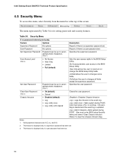
... top of the screen. Security Menu If no password entered previously: Feature Supervisor Password Options No options Description Reports if there is displayed only if a supervisor password has been set . User Password Set Supervisor Password No options Password can be up to seven alphanumeric characters. (Note 1) Sets the user access rights to continue. View Only allows the user to the BIOS Setup Utility. Clear User Password (Note 3) Chassis Intrusion • Ok (default) • Cancel • Disabled (default) • Log •...
... top of the screen. Security Menu If no password entered previously: Feature Supervisor Password Options No options Description Reports if there is displayed only if a supervisor password has been set . User Password Set Supervisor Password No options Password can be up to seven alphanumeric characters. (Note 1) Sets the user access rights to continue. View Only allows the user to the BIOS Setup Utility. Clear User Password (Note 3) Chassis Intrusion • Ok (default) • Cancel • Disabled (default) • Log •...

Product Specification
Page 96
... the Intel Boot Agent device to be available in Table 57 is used to set the boot features and the boot sequence. Specifies the boot sequence from the available types of boot devices. Disables/enables PXE boot to USB boot devices. Specifies the boot sequence from the available removable devices. Maintenance Main Advanced Security Power Boot Exit Boot Device Priority Hard Disk Drives Removable Devices ATAPI CD-ROM Drives The menu represented in the Boot Device menu. Specifies the boot sequence from Network USB Boot Boot Device Priority Hard Disk Drives Removable Devices...
... the Intel Boot Agent device to be available in Table 57 is used to set the boot features and the boot sequence. Specifies the boot sequence from the available types of boot devices. Disables/enables PXE boot to USB boot devices. Specifies the boot sequence from the available removable devices. Maintenance Main Advanced Security Power Boot Exit Boot Device Priority Hard Disk Drives Removable Devices ATAPI CD-ROM Drives The menu represented in the Boot Device menu. Specifies the boot sequence from Network USB Boot Boot Device Priority Hard Disk Drives Removable Devices...
Product Specification
Page 103
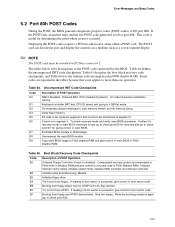
... a POST card. Keyboard controller BAT test, CPU ID saved, and going to I/O port 80h. Do necessary chipset initialization, start memory refresh, and do memory sizing. Control is uncompressed in F000:0000 in Shadow RAM and give control to check point E0 for determining the point where an error occurred. Uncompress the main BIOS module. Booting from ATAPI. Give two beeps. This code is bad, go to boot sector code. Displaying the POST-codes requires a PCI bus add...
... a POST card. Keyboard controller BAT test, CPU ID saved, and going to I/O port 80h. Do necessary chipset initialization, start memory refresh, and do memory sizing. Control is uncompressed in F000:0000 in Shadow RAM and give control to check point E0 for determining the point where an error occurred. Uncompress the main BIOS module. Booting from ATAPI. Give two beeps. This code is bad, go to boot sector code. Displaying the POST-codes requires a PCI bus add...

D865PCD_ProductGuide01_English.
Page 6
...IDE Cable 33 Connecting Internal Headers 34 Connecting the Front Panel Header 35 Connecting the USB 2.0 Header 35 Installing a Front Panel Audio Solution 36 Connecting Hardware Control and Power Cables 37 Connecting the Chassis Intrusion Cable 38 Connecting Fans ...38 Connecting Power Supply Cables 38 Add-In Card and Peripheral Interface Connectors 39 Setting the BIOS Configuration Jumper Block 40 Clearing BIOS Passwords 41 Back Panel Connectors ...42 Replacing the Battery ...43 3 Updating the BIOS ...47 Updating the BIOS with the Intel® Express BIOS Update Utility 47 Updating...
...IDE Cable 33 Connecting Internal Headers 34 Connecting the Front Panel Header 35 Connecting the USB 2.0 Header 35 Installing a Front Panel Audio Solution 36 Connecting Hardware Control and Power Cables 37 Connecting the Chassis Intrusion Cable 38 Connecting Fans ...38 Connecting Power Supply Cables 38 Add-In Card and Peripheral Interface Connectors 39 Setting the BIOS Configuration Jumper Block 40 Clearing BIOS Passwords 41 Back Panel Connectors ...42 Replacing the Battery ...43 3 Updating the BIOS ...47 Updating the BIOS with the Intel® Express BIOS Update Utility 47 Updating...

D865PCD_ProductGuide01_English.
Page 14
...Diskette drive connector Primary IDE connector Secondary IDE connector Front chassis fan header Chassis intrusion header Speaker BIOS configuration jumper Alternate power/sleep LED header Front panel header Intel 82801EB (ICH5) USB 2.0 header Battery PCI bus add-in card connectors Related Links Go to the following links for the latest information about: • Intel Desktop Board D865PCD, http://www.intel.com/design/motherbd • Processors, http://support.intel.com/support/motherboards/desktop • Audio software and utilities, http://www.intel.com/design/motherbd • LAN software...
...Diskette drive connector Primary IDE connector Secondary IDE connector Front chassis fan header Chassis intrusion header Speaker BIOS configuration jumper Alternate power/sleep LED header Front panel header Intel 82801EB (ICH5) USB 2.0 header Battery PCI bus add-in card connectors Related Links Go to the following links for the latest information about: • Intel Desktop Board D865PCD, http://www.intel.com/design/motherbd • Processors, http://support.intel.com/support/motherboards/desktop • Audio software and utilities, http://www.intel.com/design/motherbd • LAN software...
D865PCD_ProductGuide01_English.
Page 19
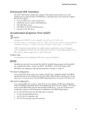
... updated by specifying manual configuration in Chapter 3 on page 47. AGP is independent of information between the processor and peripheral devices like hard disks, CD-ROM drives, and Iomega Zip* drives inside the computer. PCI Auto Configuration If you install a PCI add-in card in card. the connector is a high-performance interface for 0.8 V and 1.5 V AGP cards only; BIOS The BIOS provides the Power-On Self-Test (POST), the BIOS Setup program, the PCI and IDE auto-configuration utilities, and the video BIOS. The BIOS...
... updated by specifying manual configuration in Chapter 3 on page 47. AGP is independent of information between the processor and peripheral devices like hard disks, CD-ROM drives, and Iomega Zip* drives inside the computer. PCI Auto Configuration If you install a PCI add-in card in card. the connector is a high-performance interface for 0.8 V and 1.5 V AGP cards only; BIOS The BIOS provides the Power-On Self-Test (POST), the BIOS Setup program, the PCI and IDE auto-configuration utilities, and the video BIOS. The BIOS...
D865PCD_ProductGuide01_English.
Page 51
.... BIOS Setup Program Menu Bar Maintenance Main Advanced Security Power Boot Exit Clears passwords and Boot Integrity Service (BIS)* credentials, and configures extended configuration memory settings Allocates resources for the computer. For the latest BIOS settings, refer to the Intel® Desktop Board D865PCD Technical Product Specification or the Intel World Wide Web site: http://support.intel.com/support/motherboards/desktop NOTE For reference purposes, you make changes to the settings, update this section may not show the latest settings. Boards with BIOS...
.... BIOS Setup Program Menu Bar Maintenance Main Advanced Security Power Boot Exit Clears passwords and Boot Integrity Service (BIS)* credentials, and configures extended configuration memory settings Allocates resources for the computer. For the latest BIOS settings, refer to the Intel® Desktop Board D865PCD Technical Product Specification or the Intel World Wide Web site: http://support.intel.com/support/motherboards/desktop NOTE For reference purposes, you make changes to the settings, update this section may not show the latest settings. Boards with BIOS...
D865PCD_ProductGuide01_English.
Page 66
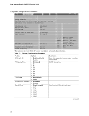
...-In Mode [Continue] [Default] Extended Configuration Chipset Memory Timing Control Graphics Core Frequency SDRAM Frequency [Default] [Auto] [Auto] m o n p Enter F1 P9 F10 ESC Select Screen Select Item Select ` Sub-Menu General Help Setup Defaults Save and Exit Exit The submenu shown in Table 23 is used to configure advanced chipset features. Intel Desktop Boards D865PCD Product Guide Chipset Configuration Submenu Main Advanced Security Power Boot Exit Chipset Configuration Setup Warning: Setting items on this option to be enabled. Alters host and I/O clock frequencies. Set PCI...
...-In Mode [Continue] [Default] Extended Configuration Chipset Memory Timing Control Graphics Core Frequency SDRAM Frequency [Default] [Auto] [Auto] m o n p Enter F1 P9 F10 ESC Select Screen Select Item Select ` Sub-Menu General Help Setup Defaults Save and Exit Exit The submenu shown in Table 23 is used to configure advanced chipset features. Intel Desktop Boards D865PCD Product Guide Chipset Configuration Submenu Main Advanced Security Power Boot Exit Chipset Configuration Setup Warning: Setting items on this option to be enabled. Alters host and I/O clock frequencies. Set PCI...

D865PCD_ProductGuide01_English.
Page 69
... Password User Password Set Supervisor Password Set User Password Clear User Password (Note 1) User access Level (Note 2) Chassis Intrusion Options Description No options Reports if there is a supervisor password set . 2. Notes: 1. Using the BIOS Setup Program Security Menu Main Advanced Security Power Boot Exit Supervisor Password : User Password : Not Installed Not Installed Set Supervisor Password Set User Password Chassis Intrusion [Disabled] m o n p Enter F1 P9 F10 ESC Select Screen Select Item Select ` Sub-Menu General Help Setup Defaults Save and Exit Exit The menu...
... Password User Password Set Supervisor Password Set User Password Clear User Password (Note 1) User access Level (Note 2) Chassis Intrusion Options Description No options Reports if there is a supervisor password set . 2. Notes: 1. Using the BIOS Setup Program Security Menu Main Advanced Security Power Boot Exit Supervisor Password : User Password : Not Installed Not Installed Set Supervisor Password Set User Password Chassis Intrusion [Disabled] m o n p Enter F1 P9 F10 ESC Select Screen Select Item Select ` Sub-Menu General Help Setup Defaults Save and Exit Exit The menu...

D865PCD_ProductGuide01_English.
Page 72
...removable devices. Intel Desktop Boards D865PCD Product Guide Boot Menu Main Advanced Security Power Boot Exit Silent BOOT Intel ® Rapid BIOS Boot Scan User Flash Area PXE Boot to LAN USB Boot ` Boot Device Priority ` Hard Disk Drives ` Removable Devices ` ATAPI CD-ROM Drives [Enabled] [Enabled] [Enabled] [Disabled] [Enabled] m o n p Enter F1 P9 F10 ESC Select Screen Select Item Select ` Sub-Menu General Help Setup Defaults Save and Exit Exit The menu shown in Table 28 is used to scan the flash ROM for user binary files that are executed at boot time. Allows BIOS to USB...
...removable devices. Intel Desktop Boards D865PCD Product Guide Boot Menu Main Advanced Security Power Boot Exit Silent BOOT Intel ® Rapid BIOS Boot Scan User Flash Area PXE Boot to LAN USB Boot ` Boot Device Priority ` Hard Disk Drives ` Removable Devices ` ATAPI CD-ROM Drives [Enabled] [Enabled] [Enabled] [Disabled] [Enabled] m o n p Enter F1 P9 F10 ESC Select Screen Select Item Select ` Sub-Menu General Help Setup Defaults Save and Exit Exit The menu shown in Table 28 is used to scan the flash ROM for user binary files that are executed at boot time. Allows BIOS to USB...
D865PCD_ProductGuide01_SChinese.
Page 52
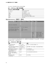
...] Enter F1 P9 F10 ESC Select Screen Select Item Select→ Sub-Menu General Help Setup Defaults Save and Exit Exit 表 11 40 页。 表 11. BIOS Setup BIOS Setup Tab> BIOS Maintenance Maintenance Main Advanced Security Power Boot Exit Clear All Passwords CPU Frequency Multiplier [13 To 1 Ratio] CPU Stepping Signature CPU Microcode Update Rev. Intel D865PCD 表 10 表 10. Maintenance 功能 选项 说明 Clear All Passwords Clear...
...] Enter F1 P9 F10 ESC Select Screen Select Item Select→ Sub-Menu General Help Setup Defaults Save and Exit Exit 表 11 40 页。 表 11. BIOS Setup BIOS Setup Tab> BIOS Maintenance Maintenance Main Advanced Security Power Boot Exit Clear All Passwords CPU Frequency Multiplier [13 To 1 Ratio] CPU Stepping Signature CPU Microcode Update Rev. Intel D865PCD 表 10 表 10. Maintenance 功能 选项 说明 Clear All Passwords Clear...


