
Product Guide
Page 4
Intel Desktop Boards D850MD and D850MV Product Guide Installing and Removing an AGP Card Retention Mechanism and Card 32 Installing the AGP Card Retention Mechanism 32 Installing an AGP Card 34 Removing the AGP Card from the Retention Mechanism 34 Removing the AGP Card Retention Mechanism 35 Connecting the IDE Cable 36 Setting the BIOS Configuration Jumper 37 Clearing Passwords...38 Replacing the Battery ...39 3 Updating the BIOS Updating the BIOS with the Intel® Express BIOS Update Utility 43 Updating the BIOS with the Intel® Flash Memory Update Utility 43 Obtaining the...
Intel Desktop Boards D850MD and D850MV Product Guide Installing and Removing an AGP Card Retention Mechanism and Card 32 Installing the AGP Card Retention Mechanism 32 Installing an AGP Card 34 Removing the AGP Card from the Retention Mechanism 34 Removing the AGP Card Retention Mechanism 35 Connecting the IDE Cable 36 Setting the BIOS Configuration Jumper 37 Clearing Passwords...38 Replacing the Battery ...39 3 Updating the BIOS Updating the BIOS with the Intel® Express BIOS Update Utility 43 Updating the BIOS with the Intel® Flash Memory Update Utility 43 Obtaining the...

Product Guide
Page 9
... connector (fan 2) (tachometer input) G Back panel connectors V Battery H ATX12V processor core voltage connector W Speaker I Processor fan connector (CPU fan) (tachometer input) X BIOS configuration jumper J Intel 82850 Memory Controller Hub (MCH) Y SCSI hard drive activity LED connector K Processor socket Z Intel 82801BA I/O Controller Hub (ICH2) L RIMM sockets AA PCI bus add-in card connectors M RIMM fan connector (fan 1) BB Communication and Networking Riser (CNR) N Power connector (optional) O Floppy drive connector Figure 1. D850MD Board Components 9 Desktop Board...
... connector (fan 2) (tachometer input) G Back panel connectors V Battery H ATX12V processor core voltage connector W Speaker I Processor fan connector (CPU fan) (tachometer input) X BIOS configuration jumper J Intel 82850 Memory Controller Hub (MCH) Y SCSI hard drive activity LED connector K Processor socket Z Intel 82801BA I/O Controller Hub (ICH2) L RIMM sockets AA PCI bus add-in card connectors M RIMM fan connector (fan 1) BB Communication and Networking Riser (CNR) N Power connector (optional) O Floppy drive connector Figure 1. D850MD Board Components 9 Desktop Board...

Product Guide
Page 10
... panel connectors V Battery H ATX12V processor core voltage connector W Speaker I Processor fan connector (CPU fan) (tachometer input) X BIOS configuration jumper J Intel 82850 Memory Controller Hub (MCH) Y SCSI hard drive activity LED connector K Processor socket Z Intel 82801BA I/O Controller Hub (ICH2) L RIMM sockets AA PCI bus add-in card connectors M RIMM fan connector (fan 1) BB Communication and Networking Riser (CNR) N Power connector (optional) O Floppy drive connector CC Chassis fan connector (fan 3) Figure 2. D850MV Board Components 10 Intel Desktop Boards D850MD...
... panel connectors V Battery H ATX12V processor core voltage connector W Speaker I Processor fan connector (CPU fan) (tachometer input) X BIOS configuration jumper J Intel 82850 Memory Controller Hub (MCH) Y SCSI hard drive activity LED connector K Processor socket Z Intel 82801BA I/O Controller Hub (ICH2) L RIMM sockets AA PCI bus add-in card connectors M RIMM fan connector (fan 1) BB Communication and Networking Riser (CNR) N Power connector (optional) O Floppy drive connector CC Chassis fan connector (fan 3) Figure 2. D850MV Board Components 10 Intel Desktop Boards D850MD...
Product Guide
Page 11
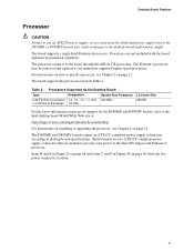
... to the board through the mPGA 478-pin socket. Processors are needed to provide extra power to the Intel 850 chipset and Pentium 4 processor. Both boards have two ATX12V compliant power supply connectors that are not included with the board and must be removed and replaced to the Intel desktop board World Wide Web site at: http://support.intel.com/support/motherboards/desktop For instructions on installing or upgrading the processor, see Chapter 2 on how to desktop board specifications. Items B and...
... to the board through the mPGA 478-pin socket. Processors are needed to provide extra power to the Intel 850 chipset and Pentium 4 processor. Both boards have two ATX12V compliant power supply connectors that are not included with the board and must be removed and replaced to the Intel desktop board World Wide Web site at: http://support.intel.com/support/motherboards/desktop For instructions on installing or upgrading the processor, see Chapter 2 on how to desktop board specifications. Items B and...

Product Guide
Page 12
.../288 Mbit technology • Single- or double-sided RIMM modules • PC600 or PC800 compliant RDRAM • Serial Presence Detect (SPD) memory only ✏ NOTE For information about installing memory, see Chapter 2 on page 21. Intel Desktop Boards D850MD and D850MV Product Guide Main Memory The board has four 2.5 V memory module sockets that support these features: • Integrated dual Direct Rambus technology memory channel • Support for a single AGP device 12
.../288 Mbit technology • Single- or double-sided RIMM modules • PC600 or PC800 compliant RDRAM • Serial Presence Detect (SPD) memory only ✏ NOTE For information about installing memory, see Chapter 2 on page 21. Intel Desktop Boards D850MD and D850MV Product Guide Main Memory The board has four 2.5 V memory module sockets that support these features: • Integrated dual Direct Rambus technology memory channel • Support for a single AGP device 12

Product Guide
Page 15
... audio, modem, USB, and LAN interfaces of the Intel 850 chipset. Desktop Board Features AGP Connector ✏ NOTE The boards are available from Intel's World Wide Web site: http://support.intel.com/support/motherboards/desktop BIOS The BIOS provides the Power-On Self-Test (POST), the BIOS Setup program, the PCI and IDE auto-configuration utilities, and the video BIOS. AD1885 analog codec ✏ NOTE The audio line out connector, located on page 43. The BIOS can be included with graphical display devices. Communication and Networking...
... audio, modem, USB, and LAN interfaces of the Intel 850 chipset. Desktop Board Features AGP Connector ✏ NOTE The boards are available from Intel's World Wide Web site: http://support.intel.com/support/motherboards/desktop BIOS The BIOS provides the Power-On Self-Test (POST), the BIOS Setup program, the PCI and IDE auto-configuration utilities, and the video BIOS. AD1885 analog codec ✏ NOTE The audio line out connector, located on page 43. The BIOS can be included with graphical display devices. Communication and Networking...

Product Guide
Page 16
... manual configuration in the BIOS automatically detects and configures the device for viewing and changing depending on whether the supervisor or user password was entered. • Setting a user password restricts who can enter either the supervisor password or the user password to access Setup. A supervisor password and a user password can be set , the computer boots without asking for booting the computer, with the following items are set , you can boot the computer. Intel Desktop Boards D850MD and D850MV Product Guide IDE Auto Configuration...
... manual configuration in the BIOS automatically detects and configures the device for viewing and changing depending on whether the supervisor or user password was entered. • Setting a user password restricts who can enter either the supervisor password or the user password to access Setup. A supervisor password and a user password can be set , the computer boots without asking for booting the computer, with the following items are set , you can boot the computer. Intel Desktop Boards D850MD and D850MV Product Guide IDE Auto Configuration...

Product Guide
Page 18
Failure to -RAM) sleep state. Instantly Available technology enables the board to enter the ACPI S3 (Suspend-to provide adequate standby current when using this feature can provide ACPI support. While in the S3 sleep state, the computer will appear to the system. The board's standby power indicator, shown in memory. Intel Desktop Boards D850MD and D850MV Product Guide Power Management Features Power management is implemented at several levels, including: • Software support: ...
Failure to -RAM) sleep state. Instantly Available technology enables the board to enter the ACPI S3 (Suspend-to provide adequate standby current when using this feature can provide ACPI support. While in the S3 sleep state, the computer will appear to the system. The board's standby power indicator, shown in memory. Intel Desktop Boards D850MD and D850MV Product Guide Power Management Features Power management is implemented at several levels, including: • Software support: ...

Product Guide
Page 37
... the BIOS configuration. Installing and Replacing Desktop Board Components Setting the BIOS Configuration Jumper CAUTION Always turn off the power and unplug the power cord from the computer before changing the jumper. Jumper Settings for the BIOS Setup Program Modes (J9H2) Function / Mode Normal Configure Recovery Jumper Setting 1-2 1 3 2-3 1 3 None 1 3 Configuration The BIOS uses current configuration information and passwords for the Setup program modes. Location of the board's BIOS configuration jumper (J9H2) is required. 37 The BIOS attempts to clear passwords. Table...
... the BIOS configuration. Installing and Replacing Desktop Board Components Setting the BIOS Configuration Jumper CAUTION Always turn off the power and unplug the power cord from the computer before changing the jumper. Jumper Settings for the BIOS Setup Program Modes (J9H2) Function / Mode Normal Configure Recovery Jumper Setting 1-2 1 3 2-3 1 3 None 1 3 Configuration The BIOS uses current configuration information and passwords for the Setup program modes. Location of the board's BIOS configuration jumper (J9H2) is required. 37 The BIOS attempts to clear passwords. Table...
Product Guide
Page 47
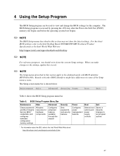
... chipset Sets passwords and security features Configures power management features Selects boot options and power supply controls Saves or discards changes to set program options * For information about the BIS, refer to the desktop boards with other BIOS identifiers might have differences in some of the Setup menu screens. 4 Using the Setup Program The BIOS Setup program can be used to the Intel Desktop Board D850MD/D850MV Technical Product Specification or the Intel World Wide Web site: http://support.intel.com/support/motherboards/desktop...
... chipset Sets passwords and security features Configures power management features Selects boot options and power supply controls Saves or discards changes to set program options * For information about the BIS, refer to the desktop boards with other BIOS identifiers might have differences in some of the Setup menu screens. 4 Using the Setup Program The BIOS Setup program can be used to the Intel Desktop Board D850MD/D850MV Technical Product Specification or the Intel World Wide Web site: http://support.intel.com/support/motherboards/desktop...
Product Guide
Page 49
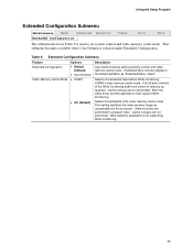
...-Combining (USWC) video memory cache mode. Memory writes are written to set system control and video memory cache mode. Extended Configuration Submenu Feature Extended Configuration Video Memory Cache Mode Options • Default (default) • User-Defined • USWC • UC (default) Description User-Defined allows setting memory control and video memory cache mode. This submenu becomes available when User Defined is used to memory as required. Cache lookups are not performed. Both the video driver and the application must support Write Combining...
...-Combining (USWC) video memory cache mode. Memory writes are written to set system control and video memory cache mode. Extended Configuration Submenu Feature Extended Configuration Video Memory Cache Mode Options • Default (default) • User-Defined • USWC • UC (default) Description User-Defined allows setting memory control and video memory cache mode. This submenu becomes available when User Defined is used to memory as required. Cache lookups are not performed. Both the video driver and the application must support Write Combining...

Product Guide
Page 51
... Maintenance Menu. Configures individual PCI slot's IRQ priority. Configures peripheral ports and devices. Configures Plug & Play and the Numlock key, and resets configuration data. When selected, displays the Event Log Configuration submenu. Advanced Menu Feature Options Extended Configuration No options PCI Configuration No options Boot Configuration No options Peripheral Configuration No options IDE Configuration Diskette Configuration No options No options Event Log Configuration No options Video Configuration No options Description If Used is used to set advanced...
... Maintenance Menu. Configures individual PCI slot's IRQ priority. Configures peripheral ports and devices. Configures Plug & Play and the Numlock key, and resets configuration data. When selected, displays the Event Log Configuration submenu. Advanced Menu Feature Options Extended Configuration No options PCI Configuration No options Boot Configuration No options Peripheral Configuration No options IDE Configuration Diskette Configuration No options No options Event Log Configuration No options Video Configuration No options Description If Used is used to set advanced...
Product Guide
Page 55
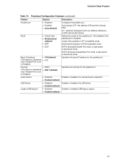
... if Parallel Port is Extended Parallel Port mode, a high-speed bi-directional mode. Using the Setup Program Table 14. An * (asterisk) displayed next to Enabled.) Audio Device • Disabled • Enabled (default) LAN Device • Disabled • Enabled (default) Legacy USB Support • Disabled • Enabled (default) Description Configures the parallel port. EPP is set to an address indicates a conflict with another device. Specifies the interrupt for the parallel port. Output Only operates in PS/2-compatible mode. Enables or disables the LAN device.
... if Parallel Port is Extended Parallel Port mode, a high-speed bi-directional mode. Using the Setup Program Table 14. An * (asterisk) displayed next to Enabled.) Audio Device • Disabled • Enabled (default) LAN Device • Disabled • Enabled (default) Legacy USB Support • Disabled • Enabled (default) Description Configures the parallel port. EPP is set to an address indicates a conflict with another device. Specifies the interrupt for the parallel port. Output Only operates in PS/2-compatible mode. Enables or disables the LAN device.

Product Guide
Page 56
... IDE controller. Intel Desktop Boards D850MD and D850MV Product Guide IDE Configuration Submenu Maintenance Main Advanced Security Power PCI Configuration Boot Configuration Peripheral Configuration IDE Configuration Diskette Configuration Event Log Configuration Video Configuration Boot This submenu shown in Table 15 is used to configure IDE device options. Primary enables only the primary IDE controller. Reports type of connected IDE device. Secondary enables only the secondary IDE controller. Specifies the hard disk drive pre-delay. When selected, displays the Primary IDE...
... IDE controller. Intel Desktop Boards D850MD and D850MV Product Guide IDE Configuration Submenu Maintenance Main Advanced Security Power PCI Configuration Boot Configuration Peripheral Configuration IDE Configuration Diskette Configuration Event Log Configuration Video Configuration Boot This submenu shown in Table 15 is used to configure IDE device options. Primary enables only the primary IDE controller. Reports type of connected IDE device. Secondary enables only the secondary IDE controller. Specifies the hard disk drive pre-delay. When selected, displays the Primary IDE...
Product Guide
Page 57
... Check the hard disk drive's specifications for transfers from the hard disk drive to be changed. • Auto (default) Auto fills-in capabilities from ATA/ATAPI device. • CD-ROM • ATAPI Removable • Other ATAPI • IDE Removable None Displays the capacity of the drive. • Disabled Enables or disables LBA mode control. • Enabled (default) • Disabled • 2 Sectors • 4 Sectors • 8 Sectors Specifies the number of these configuration options appear only if an IDE device is shown...
... Check the hard disk drive's specifications for transfers from the hard disk drive to be changed. • Auto (default) Auto fills-in capabilities from ATA/ATAPI device. • CD-ROM • ATAPI Removable • Other ATAPI • IDE Removable None Displays the capacity of the drive. • Disabled Enables or disables LBA mode control. • Enabled (default) • Disabled • 2 Sectors • 4 Sectors • 8 Sectors Specifies the number of these configuration options appear only if an IDE device is shown...
Product Guide
Page 58
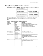
... • Disabled (default) • Enabled Description Disables or enables the integrated diskette controller. Specifies the capacity and physical size of cable connected to configure the diskette drive. Intel Desktop Boards D850MD and D850MV Product Guide Table 16. Primary/Secondary IDE Master/Slave Submenus (continued) Feature Options Description Ultra DMA None Cable Detected None Specifies the Ultra DMA mode for the drive. • Mode 0 • Mode 1 • Mode 2 • Mode 3 • Mode 4 • Mode 5 Displays the type of diskette drive A.
... • Disabled (default) • Enabled Description Disables or enables the integrated diskette controller. Specifies the capacity and physical size of cable connected to configure the diskette drive. Intel Desktop Boards D850MD and D850MV Product Guide Table 16. Primary/Secondary IDE Master/Slave Submenus (continued) Feature Options Description Ultra DMA None Cable Detected None Specifies the Ultra DMA mode for the drive. • Mode 0 • Mode 1 • Mode 2 • Mode 3 • Mode 4 • Mode 5 Displays the type of diskette drive A.

Product Guide
Page 60
...; Full (default) • Enabled • Disabled (default) Reports if there is a supervisor password set passwords and security features. This feature appears only if a user password has been set . 60 Intel Desktop Boards D850MD and D850MV Product Guide Security Menu Maintenance Main Advanced Security Power Boot The menu shown in Table 20 is entered. Sets BIOS Setup Utility access rights for user level. Specifies the supervisor password. Specifies the user password. Password can be up to complete the boot process without a password. This...
...; Full (default) • Enabled • Disabled (default) Reports if there is a supervisor password set passwords and security features. This feature appears only if a user password has been set . 60 Intel Desktop Boards D850MD and D850MV Product Guide Security Menu Maintenance Main Advanced Security Power Boot The menu shown in Table 20 is entered. Sets BIOS Setup Utility access rights for user level. Specifies the supervisor password. Specifies the user password. Password can be up to complete the boot process without a password. This...

Product Guide
Page 62
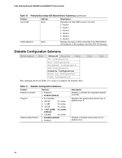
... Power APM ACPI Boot The submenu represented in the ACPI soft-off mode only, determines how the system responds to a LAN wake up event when the system is in Table 23 shows the setting options for ACPI. Maintenance Main Advanced Security Power APM ACPI Boot The menu shown in Table 22 shows the setting options for hard disks during APM standby mode. APM Submenu Feature Power Management Inactivity Timer Hard Drive Options • Disabled • Enabled (default...
... Power APM ACPI Boot The submenu represented in the ACPI soft-off mode only, determines how the system responds to a LAN wake up event when the system is in Table 23 shows the setting options for ACPI. Maintenance Main Advanced Security Power APM ACPI Boot The menu shown in Table 22 shows the setting options for hard disks during APM standby mode. APM Submenu Feature Power Management Inactivity Timer Hard Drive Options • Disabled • Enabled (default...
Product Guide
Page 63
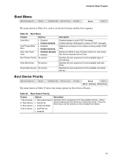
... hard disk drives. Press the Enter key to boot without running certain POST tests. Specifies the boot sequence from the available devices. Using the Setup Program Boot Menu Maintenance Main Advanced Security Power Boot Exit The menu shown in Table 25 shows the setting options for user binary files that are executed at boot time. Enables the BIOS to set the selection as the intended boot device. • ATAPI CD-ROM • Intel® Boot A • Disabled 63 Enabled displays OEM graphic instead of boot devices...
... hard disk drives. Press the Enter key to boot without running certain POST tests. Specifies the boot sequence from the available devices. Using the Setup Program Boot Menu Maintenance Main Advanced Security Power Boot Exit The menu shown in Table 25 shows the setting options for user binary files that are executed at boot time. Enables the BIOS to set the selection as the intended boot device. • ATAPI CD-ROM • Intel® Boot A • Disabled 63 Enabled displays OEM graphic instead of boot devices...

Product Guide
Page 78
... the battery has failed. Keyboard Error Error in CMOS. Intel Desktop Boards D850MD and D850MV Product Guide BIOS Error Messages When a recoverable error occurs during read sector from diskette drive. Table 32. BIOS Error Messages Error Message Explanation GA20 Error An error occurred with GateA20 when switching to boot. Pri Master HDD Error Pri Slave HDD Error Sec Master HDD Error Sec Slave HDD Error Could not read /write test of DMA controller. Run Setup to set correct values. CMOS Display Type Wrong The display type...
... the battery has failed. Keyboard Error Error in CMOS. Intel Desktop Boards D850MD and D850MV Product Guide BIOS Error Messages When a recoverable error occurs during read sector from diskette drive. Table 32. BIOS Error Messages Error Message Explanation GA20 Error An error occurred with GateA20 when switching to boot. Pri Master HDD Error Pri Slave HDD Error Sec Master HDD Error Sec Slave HDD Error Could not read /write test of DMA controller. Run Setup to set correct values. CMOS Display Type Wrong The display type...


