
Product Guide
Page 4
... AGP Card 27 Installing an AGP Card 28 Removing the AGP Card 28 Connecting the IDE Cable 29 Connecting Front Panel Headers 30 Connecting the Front Panel Header 31 Installing a Front Panel Audio Solution 31 Installing a Front Panel USB Solution 32 Connecting Fans and Power Cables 33 Connecting Fans ...33 Connecting Power Cables 33 Setting the BIOS Configuration Jumper Block 34 Clearing Passwords ...35 Replacing the Battery ...36 3 Updating the BIOS Updating the BIOS with the Intel® Express BIOS Update Utility 39 Updating the BIOS with the Intel® Flash Memory Update Utility...
... AGP Card 27 Installing an AGP Card 28 Removing the AGP Card 28 Connecting the IDE Cable 29 Connecting Front Panel Headers 30 Connecting the Front Panel Header 31 Installing a Front Panel Audio Solution 31 Installing a Front Panel USB Solution 32 Connecting Fans and Power Cables 33 Connecting Fans ...33 Connecting Power Cables 33 Setting the BIOS Configuration Jumper Block 34 Clearing Passwords ...35 Replacing the Battery ...36 3 Updating the BIOS Updating the BIOS with the Intel® Express BIOS Update Utility 39 Updating the BIOS with the Intel® Flash Memory Update Utility...

Product Guide
Page 5
Connecting the Processor Fan Heat Sink Cable to the Processor Fan Connector ........25 7. Audio Connectors ...67 16. Location of Standby Power Indicator 17 3. Installing a Processor...24 6. Front Panel Headers...30 11. Contents ATAPI CD-ROM Drives 63 Exit Menu ...64 5 Technical Reference Board Connectors ...65 Back Panel Connectors ...66 Audio Connectors...67 Add-In Card and Peripheral Interface Connectors 68 Desktop Board Resources 69 Memory Map ...69 DMA Channels ...69 Interrupts ...70 A Error Messages and Indicators BIOS Beep Codes ...71 BIOS Error Messages ...72 B ...
Connecting the Processor Fan Heat Sink Cable to the Processor Fan Connector ........25 7. Audio Connectors ...67 16. Location of Standby Power Indicator 17 3. Installing a Processor...24 6. Front Panel Headers...30 11. Contents ATAPI CD-ROM Drives 63 Exit Menu ...64 5 Technical Reference Board Connectors ...65 Back Panel Connectors ...66 Audio Connectors...67 Add-In Card and Peripheral Interface Connectors 68 Desktop Board Resources 69 Memory Map ...69 DMA Channels ...69 Interrupts ...70 A Error Messages and Indicators BIOS Beep Codes ...71 BIOS Error Messages ...72 B ...
Product Guide
Page 7
... chipset (AC '97) • Analog Devices Inc. DDR333: to six Hi-Speed Universal Serial Bus 2.0 (USB 2.0) ports • 4 Mbit Firmware Hub (FWH) Support for : • 533/400 MHz front side bus (FSB) Intel® Pentium® 4 processor in an mPGA-478 socket • 400 MHz FSB Intel® Celeron® processor in non-ECC mode) • 2.5 V memory NOTE: Desktop Board D845PESV has been designed to support DIMMs based on this Intel® desktop board. DDR333 memory...
... chipset (AC '97) • Analog Devices Inc. DDR333: to six Hi-Speed Universal Serial Bus 2.0 (USB 2.0) ports • 4 Mbit Firmware Hub (FWH) Support for : • 533/400 MHz front side bus (FSB) Intel® Pentium® 4 processor in an mPGA-478 socket • 400 MHz FSB Intel® Celeron® processor in non-ECC mode) • 2.5 V memory NOTE: Desktop Board D845PESV has been designed to support DIMMs based on this Intel® desktop board. DDR333 memory...

Product Guide
Page 13
...://support.intel.com/support/motherboards/desktop/ LAN Subsystem (Optional) The optional Intel 82562ET (with serialized IRQ support for PCI systems • PS/2-style mouse and keyboard interfaces • Interface for one via a board connector) • One parallel port with Extended Capabilities Port (ECP) and Enhanced Parallel Port (EPP) support • Serial IRQ interface compatible with the Intel 82801DB ICH4) provides a Fast PCI LAN subsystem providing both 10Base-T and 100Base-TX connectivity. Audio drivers and utilities are connected to power either...
...://support.intel.com/support/motherboards/desktop/ LAN Subsystem (Optional) The optional Intel 82562ET (with serialized IRQ support for PCI systems • PS/2-style mouse and keyboard interfaces • Interface for one via a board connector) • One parallel port with Extended Capabilities Port (ECP) and Enhanced Parallel Port (EPP) support • Serial IRQ interface compatible with the Intel 82801DB ICH4) provides a Fast PCI LAN subsystem providing both 10Base-T and 100Base-TX connectivity. Audio drivers and utilities are connected to power either...
Product Guide
Page 15
Desktop Board Features Expansion Slots Desktop Board D845PESV has the following add-in card connectors: • Six PCI bus add-in card connectors (SMBus routed to PCI bus connector 2) • One AGP connector Accelerated Graphics Port (AGP) ✏ NOTE Desktop Board D845PESV is a high-performance interface for graphics-intensive applications, such as a hard drive) in your computer, the IDE auto-configuration utility in the BIOS automatically detects and configures the device for your computer, the PCI auto-configuration utility in the BIOS automatically detects and configures the ...
Desktop Board Features Expansion Slots Desktop Board D845PESV has the following add-in card connectors: • Six PCI bus add-in card connectors (SMBus routed to PCI bus connector 2) • One AGP connector Accelerated Graphics Port (AGP) ✏ NOTE Desktop Board D845PESV is a high-performance interface for graphics-intensive applications, such as a hard drive) in your computer, the IDE auto-configuration utility in the BIOS automatically detects and configures the device for your computer, the PCI auto-configuration utility in the BIOS automatically detects and configures the ...

Product Guide
Page 16
... user passwords are set , the computer boots without asking for viewing and changing depending on the front panel, the sleep state is booted. Instantly Available technology enables the board to enter the ACPI S3 (Suspend-to access Setup. This includes the memory modules and PCI bus connectors, even when the computer appears to provide adequate standby current when using this feature can boot the computer. Setup options are set for the Setup and for the power supply...
... user passwords are set , the computer boots without asking for viewing and changing depending on the front panel, the sleep state is booted. Instantly Available technology enables the board to enter the ACPI S3 (Suspend-to access Setup. This includes the memory modules and PCI bus connectors, even when the computer appears to provide adequate standby current when using this feature can boot the computer. Setup options are set for the Setup and for the power supply...
Product Guide
Page 27
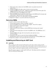
... bottom edge of the power supply, certain board components and/or traces may result across the AGP slot pins. Remove the computer's cover. 5. The desktop board has an integrated AGP card retention mechanism (RM). 27 Align the two small notches in the AGP connector, an electrical short may be damaged. Replace the computer's cover and reconnect the AC power cord. Turn off the computer...
... bottom edge of the power supply, certain board components and/or traces may result across the AGP slot pins. Remove the computer's cover. 5. The desktop board has an integrated AGP card retention mechanism (RM). 27 Align the two small notches in the AGP connector, an electrical short may be damaged. Replace the computer's cover and reconnect the AC power cord. Turn off the computer...

Product Guide
Page 31
...-L Pin Signal Name 2 AUD-GND 4 AUD-VCC 6 AUD-RET-R 8 KEY 10 AUD-RET-L To install the cable that connects the front panel audio solution to disable the back panel audio connectors. 6. Connect the audio cable to +5 V LED Out Hard disk active LED 4 HDR_BLNK_YEL Out Front panel yellow LED Reset Switch On/Off Switch 5 Ground 7 FP_RESET# In 9 +5 V Out Ground Reset switch Power 6 SWITCH_ON# In 8 Ground 10 N/C Power switch Ground Not connected Installing a Front Panel Audio Solution Figure 10, A on page 21. 2. Locate the front panel audio header...
...-L Pin Signal Name 2 AUD-GND 4 AUD-VCC 6 AUD-RET-R 8 KEY 10 AUD-RET-L To install the cable that connects the front panel audio solution to disable the back panel audio connectors. 6. Connect the audio cable to +5 V LED Out Hard disk active LED 4 HDR_BLNK_YEL Out Front panel yellow LED Reset Switch On/Off Switch 5 Ground 7 FP_RESET# In 9 +5 V Out Ground Reset switch Power 6 SWITCH_ON# In 8 Ground 10 N/C Power switch Ground Not connected Installing a Front Panel Audio Solution Figure 10, A on page 21. 2. Locate the front panel audio header...
Product Guide
Page 34
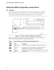
... jumper settings for booting. Moving the jumper with the power on may result in the event of a failed BIOS update. 34 Jumper Setting 31 31 31 Jumper Settings for the BIOS Setup Program Modes (J9H2) Mode Normal (default) (1-2) Configure (2-3) Recovery (None) Description The BIOS uses the current configuration and passwords for the Setup program modes. Location of the desktop board's BIOS configuration jumper is shown in BIOS Setup. The location of the BIOS Configuration Jumper Block The three-pin BIOS jumper block enables all board configurations to clear passwords. The BIOS...
... jumper settings for booting. Moving the jumper with the power on may result in the event of a failed BIOS update. 34 Jumper Setting 31 31 31 Jumper Settings for the BIOS Setup Program Modes (J9H2) Mode Normal (default) (1-2) Configure (2-3) Recovery (None) Description The BIOS uses the current configuration and passwords for the Setup program modes. Location of the desktop board's BIOS configuration jumper is shown in BIOS Setup. The location of the BIOS Configuration Jumper Block The three-pin BIOS jumper block enables all board configurations to clear passwords. The BIOS...

Product Guide
Page 35
..., plug in the computer, turn on pins 2-3 as shown below . 31 6. Setup displays the maintenance menu. 8. Place the jumper on the computer. 35 Observe the precautions in the computer and the configuration jumper block is set to boot. 7. Press to select Clear Passwords. Remove the computer cover. 12. Disconnect the computer's power cord from the AC power source. 11. Press and Setup displays a pop-up screen requesting that the board...
..., plug in the computer, turn on pins 2-3 as shown below . 31 6. Setup displays the maintenance menu. 8. Place the jumper on the computer. 35 Observe the precautions in the computer and the configuration jumper block is set to boot. 7. Press to select Clear Passwords. Remove the computer cover. 12. Disconnect the computer's power cord from the AC power source. 11. Press and Setup displays a pop-up screen requesting that the board...

Product Guide
Page 43
... Configures power management features Selects boot options and power supply controls Saves or discards changes to set program options * For information about the BIS, refer to view and change the BIOS settings for the computer. When you should write down the current Setup settings. Boards with BIOS identifier SV84510A.86A. For the latest BIOS settings, refer to the Intel® Desktop Board D845PESV Technical Product Specification or the Intel World Wide Web site: http://support.intel.com/support/motherboards/desktop...
... Configures power management features Selects boot options and power supply controls Saves or discards changes to set program options * For information about the BIS, refer to view and change the BIOS settings for the computer. When you should write down the current Setup settings. Boards with BIOS identifier SV84510A.86A. For the latest BIOS settings, refer to the Intel® Desktop Board D845PESV Technical Product Specification or the Intel World Wide Web site: http://support.intel.com/support/motherboards/desktop...

Product Guide
Page 44
... 44 Displays processor's Stepping Signature. Clears the Wired for menu screens. BIOS Setup Program Function Keys BIOS Setup Program Function Key or or Description Selects a different menu screen Moves cursor up or down Moves cursor to the next field Executes command or selects the submenu Load the default configuration values for information about the BIS, refer to clear the Setup passwords. Intel Desktop Board D845PESV Product Guide Table 9 shows the function keys available for Management Boot Integrity Service...
... 44 Displays processor's Stepping Signature. Clears the Wired for menu screens. BIOS Setup Program Function Keys BIOS Setup Program Function Key or or Description Selects a different menu screen Moves cursor up or down Moves cursor to the next field Executes command or selects the submenu Load the default configuration values for information about the BIS, refer to clear the Setup passwords. Intel Desktop Board D845PESV Product Guide Table 9 shows the function keys available for Management Boot Integrity Service...

Product Guide
Page 46
..., displays the Chipset Configuration submenu. 46 When selected, displays the Video Configuration submenu. When selected, displays the Peripheral Configuration submenu. Configures Plug & Play and the Numlock key, and resets configuration data. Configures peripheral ports and devices. Table 12. Intel Desktop Board D845PESV Product Guide Advanced Menu Maintenance Main Advanced Security Power Boot Exit PCI Configuration Boot Configuration Peripheral Configuration IDE Configuration Diskette Configuration Event Log Configuration Video Configuration USB Configuration Chipset...
..., displays the Chipset Configuration submenu. 46 When selected, displays the Video Configuration submenu. When selected, displays the Peripheral Configuration submenu. Configures Plug & Play and the Numlock key, and resets configuration data. Configures peripheral ports and devices. Table 12. Intel Desktop Board D845PESV Product Guide Advanced Menu Maintenance Main Advanced Security Power Boot Exit PCI Configuration Boot Configuration Peripheral Configuration IDE Configuration Diskette Configuration Event Log Configuration Video Configuration USB Configuration Chipset...

Product Guide
Page 51
... type of connected IDE device. Using the BIOS Setup Program IDE Configuration Submenu Maintenance Main Advanced Security Power Boot Exit PCI Configuration Boot Configuration Peripheral Configuration IDE Configuration Diskette Configuration Event Log Configuration Video Configuration USB Configuration Chipset Configuration This submenu shown in the system. • 9 Seconds • 12 Seconds • 15 Seconds • 21 Seconds • 30 Seconds Primary IDE Master No options Reports type of connected IDE device. Disabled disables the integrated IDE controller. PCI IDE Bus...
... type of connected IDE device. Using the BIOS Setup Program IDE Configuration Submenu Maintenance Main Advanced Security Power Boot Exit PCI Configuration Boot Configuration Peripheral Configuration IDE Configuration Diskette Configuration Event Log Configuration Video Configuration USB Configuration Chipset Configuration This submenu shown in the system. • 9 Seconds • 12 Seconds • 15 Seconds • 21 Seconds • 30 Seconds Primary IDE Master No options Reports type of connected IDE device. Disabled disables the integrated IDE controller. PCI IDE Bus...

Product Guide
Page 52
... Auto (default) • 0 • 1 • 2 • 3 • 4 Specifies number of these IDE submenus. User allows capabilities to memory. Table 17. continued 52 Specifies the IDE configuration mode for IDE devices. Table 17 shows the format of sectors per block for optimum setting. Intel Desktop Board D845PESV Product Guide Primary/Secondary IDE Master/Slave Submenus Maintenance Main Advanced Security PCI Configuration Boot Configuration Peripheral Configuration IDE Configuration Diskette Configuration Event Log Configuration Video Configuration USB Configuration Chipset...
... Auto (default) • 0 • 1 • 2 • 3 • 4 Specifies number of these IDE submenus. User allows capabilities to memory. Table 17. continued 52 Specifies the IDE configuration mode for IDE devices. Table 17 shows the format of sectors per block for optimum setting. Intel Desktop Board D845PESV Product Guide Primary/Secondary IDE Master/Slave Submenus Maintenance Main Advanced Security PCI Configuration Boot Configuration Peripheral Configuration IDE Configuration Diskette Configuration Event Log Configuration Video Configuration USB Configuration Chipset...

Product Guide
Page 54
Intel Desktop Board D845PESV Product Guide Diskette Configuration Submenu Maintenance Main Advanced Security Power Boot Exit PCI Configuration Boot Configuration Peripheral Configuration IDE Configuration Diskette Configuration Event Log Configuration Video Configuration USB Configuration Chipset Configuration This submenu shown in Table 18 is used to configure the floppy drive. Disables or enables diskette drive write protection. 54 Diskette Configuration Submenu Feature Diskette Controller Floppy A Floppy Write Protect Options • Disabled • Enabled (default) •...
Intel Desktop Board D845PESV Product Guide Diskette Configuration Submenu Maintenance Main Advanced Security Power Boot Exit PCI Configuration Boot Configuration Peripheral Configuration IDE Configuration Diskette Configuration Event Log Configuration Video Configuration USB Configuration Chipset Configuration This submenu shown in Table 18 is used to configure the floppy drive. Disables or enables diskette drive write protection. 54 Diskette Configuration Submenu Feature Diskette Controller Floppy A Floppy Write Protect Options • Disabled • Enabled (default) •...

Product Guide
Page 57
... USB. 57 Using the BIOS Setup Program USB Configuration Submenu Maintenance Main Advanced Security Power Boot Exit PCI Configuration Boot Configuration Peripheral Configuration IDE Configuration Diskette Configuration Event Log Configuration Video Configuration USB Configuration Chipset Configuration The menu shown in Table 21 is not available. Table 21. USB Configuration Submenu Feature High Speed USB Legacy USB Support Options • Disabled • Enabled (default) • Disabled • Enabled (default) Description Disable this option when a USB 2.0 driver is used...
... USB. 57 Using the BIOS Setup Program USB Configuration Submenu Maintenance Main Advanced Security Power Boot Exit PCI Configuration Boot Configuration Peripheral Configuration IDE Configuration Diskette Configuration Event Log Configuration Video Configuration USB Configuration Chipset Configuration The menu shown in Table 21 is not available. Table 21. USB Configuration Submenu Feature High Speed USB Legacy USB Support Options • Disabled • Enabled (default) • Disabled • Enabled (default) Description Disable this option when a USB 2.0 driver is used...

Product Guide
Page 58
... the default or user defined settings for the extended configuration options. Manual - continued 58 Intel Desktop Board D845PESV Product Guide Chipset Configuration Submenu Maintenance Main Advanced Security Power Boot Exit PCI Configuration Boot Configuration Peripheral Configuration IDE Configuration Diskette Configuration Event Log Configuration Video Configuration USB Configuration Chipset Configuration The menu shown in Table 22 is used to be programmed according to pre-change. User Defined SDRAM RAS Act. Allows override of time from read to the memory...
... the default or user defined settings for the extended configuration options. Manual - continued 58 Intel Desktop Board D845PESV Product Guide Chipset Configuration Submenu Maintenance Main Advanced Security Power Boot Exit PCI Configuration Boot Configuration Peripheral Configuration IDE Configuration Diskette Configuration Event Log Configuration Video Configuration USB Configuration Chipset Configuration The menu shown in Table 22 is used to be programmed according to pre-change. User Defined SDRAM RAS Act. Allows override of time from read to the memory...
Product Guide
Page 59
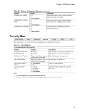
... both a user password and a supervisor password have been set . 2. Security Menu Maintenance Main Advanced Security Power Boot Exit The menu shown in memory. Set Supervisor Password Password can be up to set . Chipset Configuration Submenu (continued) Feature SDRAM CAS# Latency SDRAM RAS# to CAS# delay SDRAM RAS# Precharge Options • 2.5 • 2 • Auto (default) • 4 • 3 • 2 • Auto (default) • 4 • 3 • 2 • Auto (default) Description Selects the number of clock cycles required...
... both a user password and a supervisor password have been set . 2. Security Menu Maintenance Main Advanced Security Power Boot Exit The menu shown in memory. Set Supervisor Password Password can be up to set . Chipset Configuration Submenu (continued) Feature SDRAM CAS# Latency SDRAM RAS# to CAS# delay SDRAM RAS# Precharge Options • 2.5 • 2 • Auto (default) • 4 • 3 • 2 • Auto (default) • 4 • 3 • 2 • Auto (default) Description Selects the number of clock cycles required...

Product Guide
Page 61
...options Description Disabled displays normal POST messages. Removable Devices No options Specifies the boot sequence from the available hard disk drives. Boot Menu Feature Silent Boot Intel® Rapid BIOS Boot Scan User Flash Area PXE Boot to skip certain tests while booting. Disables or enables booting to set the boot features and the boot sequence. Using the BIOS Setup Program Boot Menu Maintenance Main Advanced Security Power Boot Exit The menu shown in Table 26 is used to USB boot devices. Specifies the boot sequence from the available ATAPI CD-ROM drives...
...options Description Disabled displays normal POST messages. Removable Devices No options Specifies the boot sequence from the available hard disk drives. Boot Menu Feature Silent Boot Intel® Rapid BIOS Boot Scan User Flash Area PXE Boot to skip certain tests while booting. Disables or enables booting to set the boot features and the boot sequence. Using the BIOS Setup Program Boot Menu Maintenance Main Advanced Security Power Boot Exit The menu shown in Table 26 is used to USB boot devices. Specifies the boot sequence from the available ATAPI CD-ROM drives...


